Crankshaft half rings. Replacement.
Great guys, I decided to share my creativity from the BZ.
Peculiar hehe) I once decided to change the half rings, but there is not a lot of specific and understandable information on the Internet, so I described in detail what kind of rings they are, where they are and why they are needed)
Where and why?
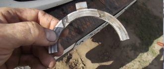
The thrust half-rings are located on the sides of the support cover of the third main bearing, i.e. Simply put, half rings are installed between the block support and the crankshaft cheeks. The half rings keep the crankshaft from axial movement and play.
Why do they need to be changed?
Over time, the half rings become thinner and the play increases, but this is not the most dangerous thing; over time, the rings can wear out to such an extent that they stop holding on and one or both fall out into the oil pan... What happens in this case? When there is nothing between the crankshaft and the block cover, the crankshaft begins to grind the support cover.
The whole unpleasantness of the situation that has arisen is that the block bearing support cover is cast together with the block to increase accuracy. Simply put, if you don’t notice crankshaft play in time, you may end up having to replace the block and the crankshaft itself... In addition, increased crankshaft play leads to constant squeezing out of the crankshaft rear oil seal and oil leaks, the rear oil seal is located behind the flywheel, and to replace it you will have to do a huge amount of work . How to determine?
Yes, very simple.
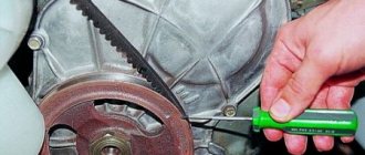
We take the mounting tool in our hands, press it into the body on one side, and with the other press on the generator pulley on the crankshaft; the axial clearance of the crankshaft should not exceed the maximum permissible - 0.35 mm. Also, have someone press the clutch while you watch the crankshaft. If you notice severe play, you must urgently replace the half rings, because if the half ring falls out, the crankshaft will grind off the groove on the bearing cover and the new half ring simply will not hold. I recommend checking the play after 120,000 miles. How to replace?
Quite simple. First you need to buy: the half rings themselves, the oil pan gasket, sealant. Since it will be necessary to drain the oil from the engine, the work of replacing the half rings can be combined with changing the oil; you can also clean the pan and oil receiver. Half rings are available in three sizes: standard 2.31; first repair 2,437; the second repair 2.56, produced by ZMZ. It is noteworthy that at the factory the half rings are installed differently - a steel-aluminum half ring is installed on the front side of the bearing (On the timing drive side), and a metal-ceramic (yellow) half ring is installed on the rear side.
The semi-rings on sale are the same, both are metal-ceramic, steel on one side and with an antifriction layer on the other. There are also non-original ones, metal-ceramic on both sides.
Source
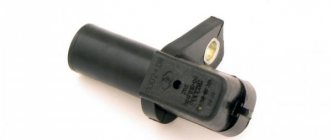
Installation of oil seals and oil pump
The 21083 engine lubrication system consists of an oil pump, oil receiver, filter and channels. After disassembling the engine, all channels must be washed with solvent and blown with compressed air. The oil pump should be installed together with the crankshaft seals, and the oil receiver should be installed after installing the ShPG and flywheel.
Installation procedure for seals and pump.
Using a thick copper or brass spacer and a hammer, drive the rear oil seal into the holder all the way. Using lithol or other grease, glue the gasket to the other side of the holder. Lubricate the inner edge of the rear oil seal and the crankshaft flange with engine oil. We put the oil seal assembly with the holder on the flange; to do this, carefully tuck the inner edge of the oil seal onto the flange using a sharp and soft wooden stick.
Replacing the oil pump seal
- After this, we slowly move the holder along the flange all the way to the cylinder block, secure it with bolts and align it so that its edge completely coincides with the edge of the block. Only after this do we tighten all the bolts completely.
- Just like the rear one, we hammer the front crankshaft oil seal into the oil pump hole.
- Lubricate the inner edge of the oil seal and pump gears with oil. To ensure uniform lubrication, turn the gears with your finger.
- Use lithol or any other consistency to glue the gasket to the oil pump.
- We rotate the drive gear so that the protrusions on it coincide with the cuts on the front of the crankshaft.
- We put the oil pump on the shaft, use a sharp soft wooden stick to tuck the lip of the oil seal onto the crankshaft journal.
- Just like the holder, we move the oil pump all the way to the block, secure it with bolts, align the edges and tighten the bolts completely.
Replacing crankshaft half rings
In addition to the cylinder head repair, it was necessary to replace the crankshaft half rings. There is not a lot of specific and understandable information on the internet, so I will tell you in detail what these rings are, where they are and why they are needed)
Where and why?
The thrust half-rings are located on the sides of the support cover of the third main bearing, i.e. Simply put, half rings are installed between the block support and the crankshaft cheeks. The half rings keep the crankshaft from axial movement and play.
Why do they need to be changed?
Over time, the half rings become thinner and the play increases, but this is not the most dangerous thing; over time, the rings can wear out to such an extent that they stop holding on and one or both fall out into the oil pan... What happens in this case? When there is nothing between the crankshaft and the block cover, the crankshaft begins to grind the support cover.
The whole unpleasantness of the situation that has arisen is that the block bearing support cover is cast together with the block to increase accuracy. Simply put, if you don’t notice crankshaft play in time, you may end up having to replace the block and the crankshaft itself... In addition, increased crankshaft play leads to constant squeezing out of the crankshaft rear oil seal and oil leaks, the rear oil seal is located behind the flywheel, and to replace it you will have to do a huge amount of work . How to determine?
Yes, very simple.
We take the mounting tool in our hands, press it into the body on one side, and with the other press on the generator pulley on the crankshaft; the axial clearance of the crankshaft should not exceed the maximum permissible - 0.35 mm. Also, have someone press the clutch while you watch the crankshaft. If you notice severe play, you must urgently replace the half rings, because if the half ring falls out, the crankshaft will grind off the groove on the bearing cover and the new half ring simply will not hold. I recommend checking the play after 120,000 miles. How to replace?
Quite simple. First you need to buy: the half rings themselves, the oil pan gasket, sealant. Since it will be necessary to drain the oil from the engine, the work of replacing the half rings can be combined with changing the oil; you can also clean the pan and oil receiver. Half rings are available in three sizes: standard 2.31; first repair 2,437; the second repair 2.56, produced by ZMZ. It is noteworthy that at the factory the half rings are installed differently - a steel-aluminum half ring is installed on the front side of the bearing (On the timing drive side), and a metal-ceramic (yellow) half ring is installed on the rear side.
The semi-rings on sale are the same, both are metal-ceramic, steel on one side and with an antifriction layer on the other. There are also non-original ones, metal-ceramic on both sides.
Source
Fault diagnosis
Diagnosis of thrust parts is usually carried out after the 120,000th mileage of the engine. It consists of three steps.
- Visually inspect the internal combustion engine for oil leaks. If they are present, this is already an indirect sign. A poorly fixed crankshaft squeezes out the oil seal responsible for sealing. And the lubricant begins to flow out.
- Loosen the generator pulley with a mounting blade, resting one end of the tool against the body. The permissible axial play should not exceed 0.35 mm.
- Press the clutch pedal from inside the car. The crankshaft should not move forward. Otherwise, this is the surest sign of breakage of the thrust half-rings.
Axial movements of the crankshaft cause a loud, irregular knock, which experienced mechanics can distinguish.
Replacing the crankshaft thrust half-rings. Eliminating backlash
In the previous entry, I discovered an unacceptably large axial play of the crankshaft of 1.4 mm. This was the reason for the clutch failure when turning right. It was necessary to remove the pan and see what happened to the thrust half-rings, since they are responsible for the axial play. To do this you will need the following:
Exhaust system gasket KKL1940450 115 RUR. (for a car with Euro-2, another code is 0K24040305) Crankshaft thrust half-rings KK1Y011SJ0 592 rub. Engine crankcase gasket 21522-2X000 146rub. Engine crankcase gasket 21521-2X000 115rub.
It is also advisable to purchase (I did not buy and therefore advise): Exhaust system bracket 0K20140352A 2 nuts K909010811B or any threads suitable for the previous bracket Gasket between the exhaust pipe and the 2nd catalyst 0K20140305B You also definitely need an assistant, sealant for the pan, a torque wrench and white -spirit. So, the intake pipe interferes with removing the pan, so we remove it. Liberally pour WD-40 onto the nuts securing the exhaust pipe to catalysts 1 and 2 and the nuts on the suspension clamp. We wait for everything to dry out and try to rip it off. Judging by the appearance of the clamp, it became clear that it would not be possible to unscrew it, everything was caked in there. When I tried to unscrew it, the pin broke off.
The catalyst nuts gave way with grief.
Then I realized that there was no need to remove the clamp at all, but rather unscrew it together with the bracket from the pallet, since the bracket had to be removed anyway, it interfered with unscrewing the pallet.
When everything is unscrewed, disconnect the oxygen sensor connector and remove the exhaust pipe.
We look at the condition of hundreds of catalysts. I have them ideally))))
Now you have access to the pallet. We unscrew the bolts securing it to the cylinder block and to the gearbox, after naturally draining the oil from it.
To remove the pan, you need to hit the protruding boss in the corner of the pan with a hammer (through a wooden block) from above through the hood; there is no other way to tear it off. Well, it’s clear that someone has to hold it from below))) So, I looked into the pan in full confidence that the half rings were in it. But to hell with it)))
To get to the half rings, you need to remove the cover of the main bearing, the second one from the gearbox.
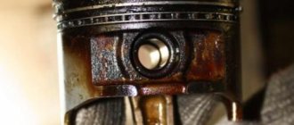
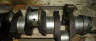
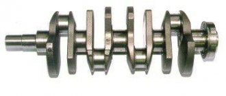
The yoke is tightened tightly. Somehow I tore it off, it’s better not to use a ratchet, otherwise you might break the teeth in it. Having removed the yoke, I saw a sad wear on the crankshaft from a worn half ring. It just cut a groove.
Use something to push the half rings out of their seats. The half ring closest to the gearbox has worn off into trash))) The half rings are made of bimetal, the anti-friction layer has completely worn off and the crankshaft has begun to rub against clean steel.
Also, the resulting groove on the crankshaft cut the yoke slightly.
Conclusion: watch the crankshaft axial play! No need to say that supposedly I don’t have clutch failure, which means everything is fine with me. When clutch failure appears, it’s already too late))) If I hadn’t climbed now, then most likely these half rings would have fallen into the pan, and then it would have been completely sad))) So, the wear on the crankshaft, although it looked scary, but it seemed smooth. The sidekick says: don’t worry, install new half-rings, everything will be fine. We insert new half rings (important: with the grooves towards the crankshaft), pushing the crankshaft axially in different directions so that the half rings fit easily. We make sure that they do not stick out from the yoke, and put on the main bearing cap, lubricating the liner with oil. We put the lid in the same position in which it was, you cannot turn it 180 degrees! Tighten the cover to a torque of 60 Nm using a torque wrench. A buddy from a car service lent it to me.
If you don’t have a torque wrench, you can tighten it using a steelyard.
Formula for calculating force: F(kg)=M(Nm)/(0.1*Lshoulder(cm)) Next, we clean the adjacent surfaces of the pan and cylinder block from the remnants of the old sealant and degrease them with white spirit. We coat the pan with sealant.
It is better to also glue the semicircular rubber gaskets from the ends of the pan to the cylinder block with sealant, because they do not fit tightly there and will fall. Then we attach the pallet and attach several bolts. The pan will not fit tightly at first due to the new gaskets, so it may seem that it does not fit into the guides. But you just need to tighten it evenly on all sides and it will press normally everywhere. Tighten the gearbox mounting bolts last. It is not necessary to tighten all the pan bolts with a torque wrench, the main thing is just not to tighten them too much, I stupidly remembered approximately how much they were tightened. Well, that’s it, while we’re putting the exhaust pipe in place, the sealant will just dry out and you can fill in the oil. I filled it with a fresh one, although I only drove 4000 km on the previous one. The filter did not change. Oh yes, the broken clamp for securing the exhaust pipe was replaced with a suitable clamp for 35 rubles. from a spare parts store for domestic cars))))
After installing the new half rings, I measured the axial play in the same way as in the previous entry. And it practically returned to the tolerance))) Instead of 1.4mm it became 0.3mm! Driving home from the garage, I deliberately tried to fly sharply into right turns and at that moment press the clutch. It never failed! It turns out the problem has been overcome! Now only after some time you need to check whether the pan is leaking. Thank you all for your attention!
Source
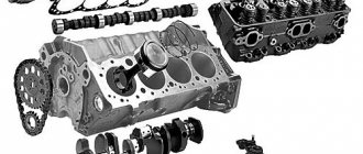
Assembling a VAZ 2106 car engine
To assemble a VAZ 2106 car engine you will need: a device for pressing in piston pins, a torque wrench, a hammer, a device for installing pistons into cylinders, keys “10”, “13”, “14”, “17”, “17”. 19", "21", "22", "36" (or gas), socket heads "12" and "13" (or a special wrench for the cylinder head bolts), screwdriver, mounting spatula. NOTE When assembling a piston with a connecting rod for VAZ 2106 engines produced before 1990, the piston and connecting rod must be aligned so that the “P” mark on the piston (shown by an arrow) is located on the side of the oil outlet holes on the lower head of the connecting rod.
On VAZ 2106 engines produced after 1990, there are no holes in the connecting rod and connecting rod bearings. The piston and connecting rod can be connected in any position.
4. Orient the piston rings. Install the rings on the remaining pistons. NOTE Orient the piston rings as follows: — the lock of the upper compression ring should be located at an angle of 30-45° to the piston pin axis; - lock of the lower compression ring - at an angle of approximately 180° to the axis of the lock of the upper compression ring; - oil scraper ring lock of the second type (or upper oil scraper ring lock of the first type) - at an angle of 30-45° to the piston pin axis between the compression ring locks; — lower oil scraper ring lock (first type) — at an angle of approximately 180° to the axis of the upper oil scraper ring lock; - expander lock - between the ring locks.5. Place the upper main bearing shells (with grooves) in the cylinder block bed.
Install thrust half-rings with notches...
23. Tighten the nuts of the connecting rod bolts with a torque wrench to the torque given in Appendix 1 Tightening torques for threaded connections of a VAZ 2106 car.
33. Install the camshaft drive chain cover with the crankshaft front oil seal, replacing the gasket. Center the holder relative to the shaft flange using a special mandrel (if there is no mandrel, center the holder along the working edge of the oil seal) and tighten the six bolts and three nuts securing the cover. 34. Install the remaining parts and assemblies in the reverse order of removal. USEFUL ADVICE After assembling the engine, it is recommended to run it on a stand. Since this cannot be done outside of special repair organizations, after installing the engine on a VAZ 2106, run it in according to a simplified cycle: 1. Make sure that the throttle valve drive is adjusted correctly, fill in oil and coolant, and check the tightness of all connections. If you are a connoisseur of girls’ elastic asses, then you just need to follow the link to see porn of beautiful asses. This site has a large collection of beauties who, after oral sex, give fuck not only in the pussy, but also in the ass, getting many anal orgasms. 2. Start the VAZ 2106 engine and let it run without load in the next cycle.
| Crankshaft rotation speed, min | Operating time, min |
| 820-900100015002000 | 2345 |
Do not bring the engine of a VAZ 2106 to maximum operating modes. 3
During operation, check the tightness of the engine and its systems, oil pressure, ignition setting, idle speed, and pay attention to the presence of extraneous noise. 4. If unusual noises or other malfunctions are detected, stop the engine and eliminate their cause. 5
Once you start operating the VAZ 2106, follow the regimes provided for the break-in period of a new car (see “Running in the VAZ 2106”).
Replacing crankshaft half rings
The crank support of the connecting rods, which creates torque, is not a flat or single piece, but several individual elements connected together. Due to this design, strong axial play appears inside the block, which can disrupt the operation of the motor. To eliminate it and stabilize the rotation, the designers came up with the idea of locking the device with special sliding bearings. The crankshaft half rings , as they are called, take on heavy loads, so they wear out soon.
Purpose, where they are located
Half rings or crescents, washers - they are called differently, they have a special purpose. They keep the crankshaft from axial displacement or longitudinal play. Essentially, these are special type bearings that establish the required clearance.
In a classic 4-cylinder engine, the crankshaft has a minimum of 5 bearing points or journals. Their contact area is quite large. This increases the friction force, which becomes even greater when the cheeks touch the supports. To minimize structural imbalance, the necks are made wider than the supports. But such a solution causes longitudinal play, which is a priori unacceptable, since the crankshaft parts begin to fail prematurely as a result.
Metal stoppers in the shape of a crescent are precisely the most effective solution that allows you to maintain the classic design, while eliminating axial displacement. This bearing differs from the standard liner in the presence of side stops or shoulders. The surfaces of the areas where the crankshaft comes into contact with them are also modified. In particular, they are made to fit a ring.
To reduce longitudinal play, washers are also suitable - one-piece rings that are installed strictly in a place specially designed for them. However, such locking elements are rarely used, since lock bearings adhere more tightly to surfaces, wear out more evenly, and are easier to install and remove. And the most important thing is that the washer is installed only on the rear main journal, and the crescents can be placed on any journal.
Structurally, the locking element is very simple. The base is made of solid bronze or steel material, on which, in some cases, an anti-friction protective layer is applied. There must be grooves or recesses for free passage of lubricant, as well as special pins that enhance fixation.
Thrust half rings are placed between the block support and the crankshaft brushes. Here they keep it from axial movement and play to the maximum extent possible. Installed on various necks. For example, in the VAZ-2106 - on the 5th main bearing, which is the first on the flywheel side. In general, according to this scheme:
Either 2 or 4 half rings are used. If two are used, then they are placed in the recesses of the lower yoke cover. And if there are four - an upper support and a removable yoke (like on tractor engines). There are also power units with one crankshaft locking crescent or just a washer.
VAZ 2106 Features of engine assembly
1. Bearing shells and thrust half-rings of the crankshaft, as well as pistons and cuffs must be lubricated with engine oil.
2. Place the main bearing shells in the cylinder block housings and in the corresponding covers.
3. Place the crankshaft with the oil pump drive gear, the camshaft drive sprocket and the gearbox input shaft bearing into the main bearings and insert two thrust half-rings into the slots of the middle cover of the main bearings.
4. Allowable axial play of the crankshaft is 0.1–0.29 mm (if the axial play is 0.35 mm or more, replace the half rings with new ones).
5. Install the main bearing caps with the lower shells in accordance with the marks and evenly tighten the nuts of the main bearing studs. Perform final tightening with a torque wrench in accordance with Fig. The sequence of tightening the bolts and nuts of the main bearing cap studs. Tightening torque 90–100 N·m (9–10) kgf·m.
6. Place the cuff cover gasket on the rear flange of the cylinder block. Place the cover with the cuff on the mandrel (Fig. Installing the rear cuff cover of engines mod.331, 3317 and 3313 using a mandrel) and, moving the cover from the mandrel to the crankshaft flange, bolt it to the cylinder block. Center the cover with the cuff in relation to the crankshaft flange using three special protrusions on the cuff cover.
7. Install the flywheel on the crankshaft. Before tightening the bolts, place three locking plates under them (one for two bolts). Tighten the bolts and bend the ends of the stop plates so as to prevent the bolts from being loosened. Make final tightening of the bolts with a torque wrench. Tightening torque 70–80 N m (7–8 kgf m)
8. Insert the liners into the bores of the cylinder block and check the amount of protrusion of the end of the liner above the plane of the block (Fig. Checking the protrusion of the end of the cylinder liner above the plane of the block of engines mod.331, 3317 and 3313). The amount of protrusion should be in the range of 0.01–0.08 mm. The check is carried out with a caliber, having previously pressed the sleeve against the block with a force of 5–7 kgf. Before installing the liners, you should especially carefully clean the ends of the sockets for the liners in the block and the seating ends on the liners themselves from scale and wear products.
9. The final installation of the liner is carried out after installing the piston with rings and connecting rod assembly into it.
10. After checking the protrusion, remove the liners from the block and install the pistons with rings and connecting rods in them. Before installing the piston with rings and connecting rods assembly into the liner, lubricate the piston rings, piston skirt and piston pin with engine oil. Install the piston rings so that their locks are located at an angle of 120° relative to each other (Fig. The relative position of the piston ring locks before installing the piston in the liner). Before installing the piston with rings into the sleeve, compress the rings with a special crimp.
11. Before final installation of the sleeves, lubricate their seating surfaces with nitro paint.
12. When installing the liner into the cylinder block, pay special attention to the correct location of the piston and connecting rod. The arrow on the piston bottom, the protrusion on the connecting rod rod and the groove on the connecting rod cap must face the direction of the camshaft drive chain drive.
13. Install the bearings into the connecting rods and connecting rod caps, having previously lubricated them with engine oil, and connect the connecting rods to the crankshaft journals, install the caps and tighten the connecting rod bolt nuts evenly. Make final tightening with a torque wrench. Tightening torque 55–65 N m (5.5–6.5 kgf m).
14. Check whether the crankshaft rotates easily in the bearings, having previously secured the liners with holder strips (see Fig. Securing cylinder liners for engines mod.331, 3317 and 3313).
15. Remove the liner holder strips from the cylinder head mounting studs and install the sealing gasket and the cylinder head with the intake pipe, exhaust manifold and fuel pump assembly onto the studs.
16. Replace a damaged or heavily compressed sealing gasket with a new one.
17. Lubricate the head gasket on both sides with a thin layer of graphite grease.
18. Tighten the cylinder head fastening nuts in the sequence shown in Fig. The procedure for tightening the nuts of the studs securing the cylinder head to the engine block mod. 331, 3317 and 3313. Make final tightening with a torque wrench. Tightening torque 90–100 N m (9–10 kgf m).
In what cases is replacement necessary?
Half rings are consumable material. When worn out they need to be replaced. Otherwise, the gradually increasing horizontal play of the connecting rod support will further accelerate the breakdown. The parts will finally wear out and stop performing their functions. And this already threatens breakdowns in the piston group. It also happens that the cylinder block breaks due to strong play in the cranked part. Therefore, replacement of the crankshaft half rings should be carried out on time as soon as the symptom appears.
The second danger of wear is that without lock washers, the shaft will begin to grind the support cover, which is cast together with the BC. Noticeable damage to the block or cover is an additional but mandatory repair. Therefore, it is so important to promptly repair damage, or rather wear, of locking parts. For example, when grinding adjacent zones of the BC, the installation of crankshaft half rings will end with their rapid abrasion. It’s good that not very noticeable damage to the necks can be eliminated by boring, and the seat can be removed by cleaning with a scraper. The large axial gap can be compensated for by repair washers, the thickness of which is 0.127 mm greater than the standard ones.
Causes of wear, loss of half rings
It happens that when disassembling the engine, thrust washers are found in the crankcase pan. On the crankshaft, in the place where these parts should be located, wear is noticeable. Parts may fall out due to the following:
In general, the main wear of the half rings occurs when the clutch is squeezed out. Especially on a cold engine in winter and sitting for a long time under a traffic light with the clutch depressed. Thus, the cause of wear may be due to insufficient qualifications of the car driver.
The fact is that squeezing the clutch transfers the entire load from the fork to the corresponding crankshaft half-ring. There are even drivers with extensive experience who constantly keep their foot on the clutch. But for this there is a special platform where the left leg should rest.
Definitions
Formally defined as a set S{\displaystyle S}, equipped with the binary operations +{\displaystyle +} and ⋅{\displaystyle \cdot }, in which for any elements a,b,c{\displaystyle a,b,c} the following hold: axioms:
- ⟨S,+⟩{\displaystyle \langle S,+\rangle } - commutative. That is, the properties take place:
- : a+b=b+a{\displaystyle a+b=b+a}
- : (a+b)+c=a+(b+c){\displaystyle (a+b)+c=a+(b+c)}
- Existence (zero): a+=+a=a{\displaystyle a+0=0+a=a}
- ⟨S,⋅⟩{\displaystyle \langle S,\cdot \rangle } — . That is, the following property holds:
- Multiplication relative to addition:
- Left distributivity: a⋅(b+c)=a⋅b+a⋅c{\displaystyle a\cdot (b+c)=a\cdot b+a\cdot c}
- Right distributivity: (a+b)⋅c=a⋅c+b⋅c{\displaystyle (a+b)\cdot c=a\cdot c+b\cdot c}
- Multiplicative property of zero:
The last axiom is omitted in the definition of a ring, since there it follows from other axioms, but here it has to be added. The only difference between a semiring and a ring is that by addition, a semiring forms only a commutative group, and not a commutative group.
A semiring is called commutative
, if the multiplication operation in it: a⋅b=b⋅a∀a,b∈S{\displaystyle a\cdot b=b\cdot a\;\forall a,b\in S}.
A semiring is called a semiring with identity
, if it exists by multiplication (called
one
): a⋅1=1⋅a=a∀a∈S{\displaystyle a\cdot 1=1\cdot a=a\;\forall a\in S}.
A semiring is called multiplicatively
(or
additively
)
reducible
if ∀a,b,c∈S{\displaystyle \;\forall a,b,c\in S} from the equality a⋅c=b⋅c{\displaystyle a\cdot c=b\ cdot c} (or, correspondingly, a+c=b+c{\displaystyle a+c=b+c}) it follows that a=b{\displaystyle a=b}.
A semiring is called idempotent
, if for any a∈S{\displaystyle a\in S} the equality a+a=a.{\displaystyle a+a=a.}
Required tools + consumables
Mandatory tools that will be needed during the work:
Replacing the support half-rings is usually accompanied by updating the engine oil, installing a new oil pan gasket and other related operations.
There are three sizes of thrust washers available on the market. Standard at 2.31, first repair and second repair (2.437 and 2.56, respectively). Therefore, you must first clarify which dimensions are suitable for your car’s engine. Typically, parts of standard or nominal sizes are installed on new or slightly worn motors. And repair ones, with increased thickness - to compensate for worn parts of the support and shaft, that is, for old and fairly worn-out internal combustion engines.
Which half rings are better, types
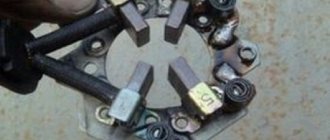
Parts of different materials are usually installed standardly - on the timing side there is a steel-aluminum or bronze ring, and on the flywheel side - metal-ceramic (yellow), bronze, copper. As a rule, the metal-ceramic version is more common on sale. If the product is original production, then one thrust washer is covered with an anti-friction layer.
Experts recommend installing bronze products. But the choice depends solely on the preferences of the owner himself. The main thing is to pay attention to the slots that should be on the parts. They are designed to allow free flow of oil to the crankshaft.
And here is some more information on the material of manufacture:
The choice of product should also imply an obligatory nuance - not only the thrust element, but also the surface of the crankshaft is subject to wear during engine operation. Therefore, it is extremely important to be able to select the correct stopper size, type and serial number. It is imperative that the parts fully meet the standard requirements and are covered with a special protective layer.
As a rule, the exact size is determined before the actual replacement process. However, this can only be done by a specialist who has been able, based on indirect evidence, to create a picture of what reigns inside the block. In other words, how worn are the mounting sockets, and what size washers should be installed. Therefore, under normal conditions, when the installation is done by hand, you have to determine this during the work. If, after installing the half-rings, a measurement with a flat feeler gauge shows a play value higher than the standard - 0.06-0.26 mm or 0.35 mm, the locking elements must be changed one size higher.
Replacement process
To correctly carry out the replacement, you must act strictly according to the instructions, performing the steps sequentially:
To facilitate installation, you need to move the crankshaft with a screwdriver and at the same time rest the new half-rings with their ends against the old parts. This way you can squeeze them out faster, and the spare parts of the repair kit will fit into place.
When installing the half rings, their slots or recesses should face inward, towards the crankshaft.
Replacing oil seals
If the crankshaft oil seals have been squeezed out due to axial displacement, both will have to be replaced with new ones. One is installed on the pulley side, the second on the flywheel. It is extremely important to replace the first seal, which is on the timing side. Because oil will leak out and get on the belt. And this is a serious risk of slipping one or several teeth or even worse - breaking. What will happen is known: it will be necessary to change the valves, since the rods will be bent or broken when they meet the pistons.
The front oil seal can be replaced from the gas distribution mechanism side. It will be necessary to remove the protective casing, belt, and crankshaft toothed pulley. Then remove the cuff and install a new one. But the rear oil seal is more difficult to change. It is necessary to dismantle the gearbox and clutch. After removing the cuff, thoroughly clean the seat, and only then install a new product.
It is imperative to make sure that the half rings are assembled and installed correctly at the final stage. To do this, the crankshaft is turned by hand - rotation should continue automatically (0.5 turns), be smooth, without any jamming.
Source
Just the facts
These half rings were dismantled from the ZMZ 409 installed on the Patriot. The mileage of the car is 30 thousand. Year of manufacture is 2015. Plastic half-rings were on the pulley side, “metal” half-rings were on the flywheel side. The logic is clear. We constantly work with the clutch, which means that on this side we need to install something stronger. The other thing is unclear. What does this penny saving mean on the scale of engine production at the plant? Big money? Hardly. But the thought that with such “designers and managers” we don’t need any “spies and enemies” sometimes occurs to me. Plastic half rings can last quite a long time, but they can crumble in a minute. For example, when replacing the front cuff in a Papuan service center, when the crankshaft pulley will be driven in with a hammer or sledgehammer.