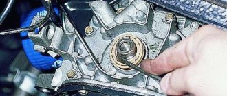
Good day, dear reader. In this topic, we will analyze such a reason as the crankshaft stroke due to wear of the half rings. The permissible crankshaft play is 0.25 mm; if it is more, then it is necessary to replace the worn crankshaft half rings.
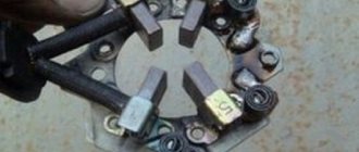
Half rings
As the half rings wear out, the crankshaft begins to move and the following problems begin. We cannot move the car smoothly, we cannot adjust the clutch so that the release bearing has free play and does not spin constantly. The clutch pedal starts moving from front to back. In general, good things are not enough, it’s time for repairs
Installation of VAZ 21083 engine
Photo. Box boot VAZ 21083
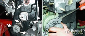
You can immediately lubricate the release bearing with oil, preferably transmission oil or mixed with lithol; it can be pressed with a syringe through the slot shown in the photo below.
Photo. Release bearing of VAZ 21083 engine.
We install the engine as we removed it through the bottom without the head; this can be easily done at home with two people. To do this, pass a belt or rope under the engine, place a thick rag on the front of the car and using a pipe or crowbar you can effortlessly pull the engine onto the box, as shown in the photo below. Bolt the box, lift the engine, screw on the mount, the engine is installed, all that remains is to install the head.
Photo. Installing the VAZ 21083 engine through the bottom.
Great guys, I decided to share my creativity from the BZ. Peculiar hehe)
Once I decided to change the half rings, but there is not a lot of concrete and understandable information on the internet, so I described in detail what kind of rings they are, where they are and why they are needed)
Where and why?
The thrust half-rings are located on the sides of the support cover of the third main bearing, i.e. Simply put, half rings are installed between the block support and the crankshaft cheeks. The half rings keep the crankshaft from axial movement and play.
Why do they need to be changed?
Over time, the half rings become thinner and the play increases, but this is not the most dangerous thing; over time, the rings can wear out to such an extent that they stop holding on and one or both fall out into the oil pan... What happens in this case? When there is nothing between the crankshaft and the block cover, the crankshaft begins to grind the support cover.
The whole unpleasantness of the situation that has arisen is that the block bearing support cover is cast together with the block to increase accuracy. Simply put, if you don’t notice crankshaft play in time, you may end up having to replace the block and the crankshaft itself... In addition, increased crankshaft play leads to constant squeezing out of the crankshaft rear oil seal and oil leaks, the rear oil seal is located behind the flywheel, and to replace it you will have to do a huge amount of work . How to determine?
Yes, very simple.
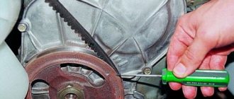
We take the mounting tool in our hands, press it into the body on one side, and with the other press on the generator pulley on the crankshaft; the axial clearance of the crankshaft should not exceed the maximum permissible - 0.35 mm. Also, have someone press the clutch while you watch the crankshaft. If you notice severe play, you must urgently replace the half rings, because if the half ring falls out, the crankshaft will grind off the groove on the bearing cover and the new half ring simply will not hold. I recommend checking the play after 120,000 miles. How to replace?
Quite simple. First you need to buy: the half rings themselves, the oil pan gasket, sealant. Since it will be necessary to drain the oil from the engine, the work of replacing the half rings can be combined with changing the oil; you can also clean the pan and oil receiver. Half rings are available in three sizes: standard 2.31; first repair 2,437; the second repair 2.56, produced by ZMZ. It is noteworthy that at the factory the half rings are installed differently - a steel-aluminum half ring is installed on the front side of the bearing (On the timing drive side), and a metal-ceramic (yellow) half ring is installed on the rear side.
The semi-rings on sale are the same, both are metal-ceramic, steel on one side and with an antifriction layer on the other. There are also non-original ones, metal-ceramic on both sides.
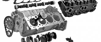
Gasoline engine on the "eight"
The appearance of the VAZ 21083 gasoline engine is directly related to the low quality of domestic rubber products. The fact is that at the very beginning of production, the Lada Samara family of cars was equipped with a VAZ 2108 engine, the first domestic power unit designed specifically for transverse placement under the hood of a front-wheel drive car.
However, the VAZ 2108 engine had an unpleasant feature, also characteristic of foreign engines with a timing belt drive. When the timing belt breaks, the engine pistons meet the cylinder head valves, and the latter inevitably bend, which leads to expensive repairs of the VAZ 2108 engine. On foreign cars, such a breakdown occurred extremely rarely due to the high reliability of timing belts. However, in the first Samaras, the breakage of a low-quality belt was such a frequent occurrence that it was necessary to urgently modify the engine with the help of specialists from German automakers. As a result, a new engine appeared, which became the progenitor of a whole family of power units. Assembling a VAZ 21083 engine is not a difficult task; it can be completed without the help of specialists.
In what cases is replacement necessary?
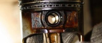
Half rings are consumable material. When worn out they need to be replaced. Otherwise, the gradually increasing horizontal play of the connecting rod support will further accelerate the breakdown. The parts will finally wear out and stop performing their functions. And this already threatens breakdowns in the piston group. It also happens that the cylinder block breaks due to strong play in the cranked part. Therefore, replacement of the crankshaft half rings should be carried out on time as soon as the symptom appears.
The second danger of wear is that without lock washers, the shaft will begin to grind the support cover, which is cast together with the BC. Noticeable damage to the block or cover is an additional but mandatory repair. Therefore, it is so important to promptly repair damage, or rather wear, of locking parts. For example, when grinding adjacent zones of the BC, the installation of crankshaft half rings will end with their rapid abrasion. It’s good that not very noticeable damage to the necks can be eliminated by boring, and the seat can be removed by cleaning with a scraper. The large axial gap can be compensated for by repair washers, the thickness of which is 0.127 mm greater than the standard ones.
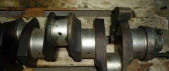
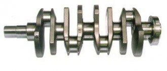
Crankshaft repair
How to replace piston rings yourself
The crankshaft removed from the car is thoroughly cleaned and inspected. The presence of cracks on the main and connecting rod journals, as well as on the cheeks, is not allowed. If they are found, the crankshaft can be submitted for welding, but it would be better to replace it. Typically, restored crankshafts do not last more than 50 thousand km. They also check for the presence of deep grooves, burrs, scratches and nicks at the contact point of the VAZ 2106 crankshaft oil seal.
To determine the runout, as well as the displacement of the axes of the connecting rod journals, the crank is mounted on prisms. The values of radial runout, axial displacement and non-perpendicularity of the flange end to the crankshaft axis are measured. If the permissible parameters are exceeded, a decision is made to replace the part or edit it using a hydraulic press. Let us immediately note that the VAZ 2106 crankshafts are made of cast iron, so attempts to correct its geometry with a press often end in part failure.
Next, measurements are taken of the parameters of the journals (connecting rod and main). When they are produced to a size that is 0.005 mm less than the minimum allowable (for this repair size) and (or) their ovality is exceeded by more than 0.05 mm, a decision is made whether grinding and replacement of the crankshaft liners is necessary. The journals must be ground to the closest size (according to the repair size chart). The center-to-center distance between the main and connecting rod journals should ensure a piston stroke from 79.9 mm to 80.05 mm.
Required tolerances for the dimensions of the VAZ 2106 crankshaft after grinding:
- when installing 1 and 5 necks on prisms, runout of 2, 3 and 4 necks is not allowed by more than 0.03 mm;
- runout of the seat for the crankshaft bearing and sprocket - up to 0.04 mm;
- taper, as well as ovality of the connecting rod journals - up to 0.007 mm.
Before assembly, remove the plugs from the crankshaft, clean and wash the oil channels. After this, blow with compressed air and install new plugs.
Signs of a bad crankshaft
What types of piston rings are there?
There are several signs that can directly or indirectly indicate a crankshaft malfunction:
- when the engine is running at low speeds, the oil pressure indicator light comes on;
- when operating at medium and high speeds, a metallic knock can be clearly heard, the frequency of which increases with increasing speed;
- engine jamming.
In the first two cases, the cause of the malfunction is the wear of the connecting rod or main journals of the crank. The increased gap between the surface of the journal and the liner is what causes a drop in oil pressure. With a critically large gap, the shaft may run out, which causes knocking (the engine “knocks”). The third case is the most difficult. Only a small portion of crankshafts from seized engines can be repaired. In most cases, the crankshaft will need to be replaced.
Upper half ring
The upper half rings are attached to the ends of the cylinder block, and the lower ones have projections for fixing them in the rear main bearing cover.
The upper half-rings of the weights are installed by the pipelayer on top of the string so that the mounting holes of the upper and lower half-rings are aligned.
The two upper half rings encircle the nipple part of the drill pipe, and the two lower half rings encircle the coupling part of the drill pipe. Between the upper and lower half rings, studs are inserted, between which a cable is laid, which is clamped with bolts. The upper and lower half rings are tightened with bolts.
The two upper half rings encircle the nipple part of the drill pipe, and the two lower ones encircle the coupling part of the drill pipe. Between the upper and lower half rings, studs are inserted, between which the cable is laid using clamping bolts. The upper and lower half rings are tightened with bolts.
The two upper half rings encircle the nipple part of the drill pipe, and the two lower half rings encircle the coupling part of the drill pipe. Between the upper and lower half rings, studs are inserted, between which a cable is laid, which is clamped with bolts. The upper and lower half rings are tightened with bolts.
In the upper half ring of the logogram, the symbols of the API classification given in table. 2, information is provided on the scope of application and the level of a number of the most important operational properties of the oil.
We determine the force acting on the upper semiring, as in Example 2.3, using (2.32) and (2.3) without replacing the nonlinear system with its linear model. Let us define the current induction B and express through it the flow Ф, B S.
Let's cut the ring in half with a meridian section and look at the upper half ring.
Next, the lower half-rings are disconnected from the upper ones, and the upper half-rings with the rods attached to them are transferred to a new section of the pipe. There the lower half rings are attached to the upper ones.
Then the half rings are firmly fastened with bolts 3, having previously moved them so that the upper half rings tightly squeeze the corner placed between them.
Due to the elimination of these short, high-lying sections of busbars, it is necessary to partially run the lines under the upper semi-ring of the busbars, and two of the phases of the lines must be wound partially above the slopes to the switch. Considering the short spans of the upper semi-ring of the tires and the short spans to the nearest linear supports, it is impossible to imagine that such an arrangement could cause any inconvenience in operation.
Upon completion of assembly, turn the frame to its original position, remove the fixing pins, fold the upper half-rings onto the stops and remove the frame from the stand. To straighten minor bends in the longitudinal beams of the assembled frame, it is placed on a stand as indicated above, and depending on the nature of the bending of the longitudinal beams, the frame is rotated to a position convenient for straightening.
To assemble the frame, set the rotating rings to their original position, remove the locking pin and fold the upper half rings onto the stops; then a movable stand and movable stops are installed in accordance with the assembled frame, the longitudinal beams of the frame are installed and secured, cross-beams, brackets and other parts are riveted to them in accordance with the accepted technological process.
Indeed, if the master device jerks slider B beyond the position of slider A or B, then the upper half-ring becomes working, and the lower half-ring becomes backup. As long as the advance angle from any equilibrium state is a180, the sign of the imbalance is maintained and the servo drive operates correctly, in the same direction. Point 5 is a point of false equilibrium - if a is 180, engine B from point 4 goes to point 5 and there will be no processing.
We also believe that this design is dangerous for repair workers when performing inspections, tests or repairs on the upper half ring of tires. Our experience in the 138 kV voltage class has shown that preference should be given to a rigid busbar supported by supporting insulators rather than a flexible busbar.
Installation of oil seals and oil pump
The 21083 engine lubrication system consists of an oil pump, oil receiver, filter and channels. After disassembling the engine, all channels must be washed with solvent and blown with compressed air. The oil pump should be installed together with the crankshaft seals, and the oil receiver should be installed after installing the ShPG and flywheel.
Installation procedure for seals and pump.
Using a thick copper or brass spacer and a hammer, drive the rear oil seal into the holder all the way. Using lithol or other grease, glue the gasket to the other side of the holder. Lubricate the inner edge of the rear oil seal and the crankshaft flange with engine oil. We put the oil seal assembly with the holder on the flange; to do this, carefully tuck the inner edge of the oil seal onto the flange using a sharp and soft wooden stick.
Replacing the oil pump seal
- After this, we slowly move the holder along the flange all the way to the cylinder block, secure it with bolts and align it so that its edge completely coincides with the edge of the block. Only after this do we tighten all the bolts completely.
- Just like the rear one, we hammer the front crankshaft oil seal into the oil pump hole.
- Lubricate the inner edge of the oil seal and pump gears with oil. To ensure uniform lubrication, turn the gears with your finger.
- Use lithol or any other consistency to glue the gasket to the oil pump.
- We rotate the drive gear so that the protrusions on it coincide with the cuts on the front of the crankshaft.
- We put the oil pump on the shaft, use a sharp soft wooden stick to tuck the lip of the oil seal onto the crankshaft journal.
- Just like the holder, we move the oil pump all the way to the block, secure it with bolts, align the edges and tighten the bolts completely.
Preparation for replacing bearings and direct installation of the crankshaft
In addition, disconnect parts such as the generator, starter, coolant pump, upper nuts that secure the engine mount, and bolts that secure the clutch housing to the engine. The order in which disconnection is made must be strictly observed. During operation, the lifting device cables must be secured to the block and carefully lifted.
Using a 10mm wrench, you need to unscrew all the bolts that secure the oil pan to the cylinder block and remove it along with the seal gasket. Disconnect the oil pump. Using a 14mm socket, unscrew the nuts that secure the connecting rod cover, and then remove it. Then take a hammer, press the handle against the connecting rod, and push the pistons out of the cylinders. Next, take a 17mm socket and unscrew the bolts that attach the crankshaft to the cover. Counting from the crankshaft toe, according to the number marks, we disconnect all subsequent covers. Keep in mind that on cover 5 there are two marks on both sides.
Assembling a VAZ 2106 car engine
To assemble a VAZ 2106 car engine you will need: a device for pressing in piston pins, a torque wrench, a hammer, a device for installing pistons into cylinders, keys “10”, “13”, “14”, “17”, “17”. 19", "21", "22", "36" (or gas), socket heads "12" and "13" (or a special wrench for the cylinder head bolts), screwdriver, mounting spatula. NOTE When assembling a piston with a connecting rod for VAZ 2106 engines produced before 1990, the piston and connecting rod must be aligned so that the “P” mark on the piston (shown by an arrow) is located on the side of the oil outlet holes on the lower head of the connecting rod.
On VAZ 2106 engines produced after 1990, there are no holes in the connecting rod and connecting rod bearings. The piston and connecting rod can be connected in any position.
4. Orient the piston rings. Install the rings on the remaining pistons. NOTE Orient the piston rings as follows: — the lock of the upper compression ring should be located at an angle of 30-45° to the piston pin axis; - lock of the lower compression ring - at an angle of approximately 180° to the axis of the lock of the upper compression ring; - oil scraper ring lock of the second type (or upper oil scraper ring lock of the first type) - at an angle of 30-45° to the piston pin axis between the compression ring locks; — lower oil scraper ring lock (first type) — at an angle of approximately 180° to the axis of the upper oil scraper ring lock; - expander lock - between the ring locks.5. Place the upper main bearing shells (with grooves) in the cylinder block bed.
Install thrust half-rings with notches...
23. Tighten the nuts of the connecting rod bolts with a torque wrench to the torque given in Appendix 1 Tightening torques for threaded connections of a VAZ 2106 car.
33. Install the camshaft drive chain cover with the crankshaft front oil seal, replacing the gasket. Center the holder relative to the shaft flange using a special mandrel (if there is no mandrel, center the holder along the working edge of the oil seal) and tighten the six bolts and three nuts securing the cover. 34. Install the remaining parts and assemblies in the reverse order of removal. USEFUL ADVICE After assembling the engine, it is recommended to run it on a stand. Since this cannot be done outside of special repair organizations, after installing the engine on a VAZ 2106, run it in according to a simplified cycle: 1. Make sure that the throttle valve drive is adjusted correctly, fill in oil and coolant, and check the tightness of all connections. If you are a connoisseur of girls’ elastic asses, then you just need to follow the link to see porn of beautiful asses. This site has a large collection of beauties who, after oral sex, give fuck not only in the pussy, but also in the ass, getting many anal orgasms. 2. Start the VAZ 2106 engine and let it run without load in the next cycle.
| Crankshaft rotation speed, min | Operating time, min |
| 820-900100015002000 | 2345 |
Do not bring the engine of a VAZ 2106 to maximum operating modes. 3
During operation, check the tightness of the engine and its systems, oil pressure, ignition setting, idle speed, and pay attention to the presence of extraneous noise. 4. If unusual noises or other malfunctions are detected, stop the engine and eliminate their cause. 5
Once you start operating the VAZ 2106, follow the regimes provided for the break-in period of a new car (see “Running in the VAZ 2106”).
Required tools + consumables
Mandatory tools that will be needed during the work:
- set of wrenches and sockets;
- set of screwdrivers;
- torque wrench for proper tightening of bolts;
- a flat feeler gauge for measuring axial play, or even better, a special indicator with a scale;
- clean rag.
- new half rings;
- pan gasket;
- sealant.
Replacing the support half-rings is usually accompanied by updating the engine oil, installing a new oil pan gasket and other related operations.
There are three sizes of thrust washers available on the market. Standard at 2.31, first repair and second repair (2.437 and 2.56, respectively). Therefore, you must first clarify which dimensions are suitable for your car’s engine. Typically, parts of standard or nominal sizes are installed on new or slightly worn motors. And repair ones, with increased thickness - to compensate for worn parts of the support and shaft, that is, for old and fairly worn-out internal combustion engines.
Examples of semirings
- Semiring ⟨N,+,⋅⟩{\displaystyle \langle \mathbb {N} _{0},+,\cdot \rangle } .
- Trivial semiring: ⟨{},+,⋅⟩{\displaystyle \langle \lbrace 0\rbrace ,+,\cdot \rangle }
- Two-element semirings: ⟨Z2,+,⋅⟩{\displaystyle \langle \mathbb {Z} _{2},+,\cdot \rangle }, ⟨B,⊕,∨⟩{\displaystyle \langle \mathbb {B} ,\oplus ,\vee \rangle }, where ∨{\displaystyle \vee } denotes , and ⊕{\displaystyle \oplus } is the logical operation "" on the set B={,1}{\displaystyle \mathbb {B} = \lbrace 0,1\rbrace }
- Square n×n{\displaystyle n\times n} with elements from the semiring N{\displaystyle \mathbb {N} _{0}} and operations of matrix addition and multiplication. Also, a semiring is formed by square matrices with elements from any semiring.
- If A{\displaystyle A} is a commutative monoid, then the set End(A){\displaystyle \operatorname {End} (A)} A{\displaystyle A} forms a semiring, where addition is defined pointwise and multiplication is defined as a composition of functions .
- Nx{\displaystyle \mathbb {N} } - with natural coefficients - form a commutative semiring; is a free commutative semiring with a unique generator {x}{\displaystyle \{x\}}.
- Probability semiring - non-negative real numbers with the usual operations of addition and multiplication.
- (max,+){\displaystyle (\max ,+)} and (min,+){\displaystyle (\min ,+)} are semirings of real numbers in which addition is defined as taking the maximum (respectively the minimum), and multiplication - like ordinary addition of real numbers.
VAZ 2106 Features of engine assembly
1. Bearing shells and thrust half-rings of the crankshaft, as well as pistons and cuffs must be lubricated with engine oil.
2. Place the main bearing shells in the cylinder block housings and in the corresponding covers.
3. Place the crankshaft with the oil pump drive gear, the camshaft drive sprocket and the gearbox input shaft bearing into the main bearings and insert two thrust half-rings into the slots of the middle cover of the main bearings.
4. Allowable axial play of the crankshaft is 0.1–0.29 mm (if the axial play is 0.35 mm or more, replace the half rings with new ones).
5. Install the main bearing caps with the lower shells in accordance with the marks and evenly tighten the nuts of the main bearing studs. Perform final tightening with a torque wrench in accordance with Fig. The sequence of tightening the bolts and nuts of the main bearing cap studs. Tightening torque 90–100 N·m (9–10) kgf·m.
6. Place the cuff cover gasket on the rear flange of the cylinder block. Place the cover with the cuff on the mandrel (Fig. Installing the rear cuff cover of engines mod.331, 3317 and 3313 using a mandrel) and, moving the cover from the mandrel to the crankshaft flange, bolt it to the cylinder block. Center the cover with the cuff in relation to the crankshaft flange using three special protrusions on the cuff cover.
7. Install the flywheel on the crankshaft. Before tightening the bolts, place three locking plates under them (one for two bolts). Tighten the bolts and bend the ends of the stop plates so as to prevent the bolts from being loosened. Make final tightening of the bolts with a torque wrench. Tightening torque 70–80 N m (7–8 kgf m)
8. Insert the liners into the bores of the cylinder block and check the amount of protrusion of the end of the liner above the plane of the block (Fig. Checking the protrusion of the end of the cylinder liner above the plane of the block of engines mod.331, 3317 and 3313). The amount of protrusion should be in the range of 0.01–0.08 mm. The check is carried out with a caliber, having previously pressed the sleeve against the block with a force of 5–7 kgf. Before installing the liners, you should especially carefully clean the ends of the sockets for the liners in the block and the seating ends on the liners themselves from scale and wear products.
9. The final installation of the liner is carried out after installing the piston with rings and connecting rod assembly into it.
10. After checking the protrusion, remove the liners from the block and install the pistons with rings and connecting rods in them. Before installing the piston with rings and connecting rods assembly into the liner, lubricate the piston rings, piston skirt and piston pin with engine oil. Install the piston rings so that their locks are located at an angle of 120° relative to each other (Fig. The relative position of the piston ring locks before installing the piston in the liner). Before installing the piston with rings into the sleeve, compress the rings with a special crimp.
11. Before final installation of the sleeves, lubricate their seating surfaces with nitro paint.
12. When installing the liner into the cylinder block, pay special attention to the correct location of the piston and connecting rod. The arrow on the piston bottom, the protrusion on the connecting rod rod and the groove on the connecting rod cap must face the direction of the camshaft drive chain drive.
13. Install the bearings into the connecting rods and connecting rod caps, having previously lubricated them with engine oil, and connect the connecting rods to the crankshaft journals, install the caps and tighten the connecting rod bolt nuts evenly. Make final tightening with a torque wrench. Tightening torque 55–65 N m (5.5–6.5 kgf m).
14. Check whether the crankshaft rotates easily in the bearings, having previously secured the liners with holder strips (see Fig. Securing cylinder liners for engines mod.331, 3317 and 3313).
15. Remove the liner holder strips from the cylinder head mounting studs and install the sealing gasket and the cylinder head with the intake pipe, exhaust manifold and fuel pump assembly onto the studs.
16. Replace a damaged or heavily compressed sealing gasket with a new one.
17. Lubricate the head gasket on both sides with a thin layer of graphite grease.
18. Tighten the cylinder head fastening nuts in the sequence shown in Fig. The procedure for tightening the nuts of the studs securing the cylinder head to the engine block mod. 331, 3317 and 3313. Make final tightening with a torque wrench. Tightening torque 90–100 N m (9–10 kgf m).
Types and design of crankshaft support half-rings
To reduce crankshaft play, two types of parts are used:
Washers are one-piece rings that are mounted in the support of the rear journal of the crankshaft. Half rings are half rings that are mounted on the support of the rear or one of the middle journals of the crankshaft. Today, half rings are most used, since they provide the best fit to the thrust surfaces of the crankshaft and wear more evenly, and are convenient for installation/disassembly. In addition, washers can only be installed on the rear journal of the shaft, while half rings can be installed on any journal.
Structurally, the half rings and washers are very simple. They are based on a solid bronze or stamped steel half-ring/ring, onto which an anti-friction coating is applied, which reduces friction against the thrust surface on the shaft cheek. The antifriction layer has two or more vertical (in some cases radial) grooves for free passage of oil. Also, the ring/semi-ring may have holes and fixing pins of various shapes to prevent rotation of the part.
Definitions
Formally defined as a set S{\displaystyle S}, equipped with the binary operations +{\displaystyle +} and ⋅{\displaystyle \cdot }, in which for any elements a,b,c{\displaystyle a,b,c} the following hold: axioms:
- ⟨S,+⟩{\displaystyle \langle S,+\rangle } - commutative. That is, the properties take place:
- : a+b=b+a{\displaystyle a+b=b+a}
- : (a+b)+c=a+(b+c){\displaystyle (a+b)+c=a+(b+c)}
- Existence (zero): a+=+a=a{\displaystyle a+0=0+a=a}
- ⟨S,⋅⟩{\displaystyle \langle S,\cdot \rangle } — . That is, the following property holds:
- Multiplication relative to addition:
- Left distributivity: a⋅(b+c)=a⋅b+a⋅c{\displaystyle a\cdot (b+c)=a\cdot b+a\cdot c}
- Right distributivity: (a+b)⋅c=a⋅c+b⋅c{\displaystyle (a+b)\cdot c=a\cdot c+b\cdot c}
- Multiplicative property of zero:
The last axiom is omitted in the definition of a ring, since there it follows from other axioms, but here it has to be added. The only difference between a semiring and a ring is that by addition, a semiring forms only a commutative group, and not a commutative group.
A semiring is called commutative
, if the multiplication operation in it: a⋅b=b⋅a∀a,b∈S{\displaystyle a\cdot b=b\cdot a\;\forall a,b\in S}.
A semiring is called a semiring with identity
, if it exists by multiplication (called
one
): a⋅1=1⋅a=a∀a∈S{\displaystyle a\cdot 1=1\cdot a=a\;\forall a\in S}.
A semiring is called multiplicatively
(or
additively
)
reducible
if ∀a,b,c∈S{\displaystyle \;\forall a,b,c\in S} from the equality a⋅c=b⋅c{\displaystyle a\cdot c=b\ cdot c} (or, correspondingly, a+c=b+c{\displaystyle a+c=b+c}) it follows that a=b{\displaystyle a=b}.
A semiring is called idempotent
, if for any a∈S{\displaystyle a\in S} the equality a+a=a.{\displaystyle a+a=a.}
Symptoms of a problem
If you repair the crankshaft yourself, you can save a lot on car service costs. Therefore, it is worth understanding its diagnosis, repair and installation. If repairs are not carried out in a timely manner, the engine may seize, and this can lead to more serious repairs. The following are signs that serve to identify malfunctions:
- when the engine is running, the oil level control light does not go out, which indicates a decrease in oil pressure in the system;
- at medium and high speeds a metallic knock is heard in the engine, which increases with increasing speed;
- engine jams.
The cause of the first two malfunctions is the wear of the main and connecting rod journals. In this case, the distance between the neck and the liner increases, which leads to a decrease in oil pressure. If the distance is too large, the shaft may run out, causing metallic sounds in the engine. If the engine jams, it is better to replace the crankshaft. To diagnose the serviceability of the crankshaft, it should be dismantled and cleaned. It is better to remove the part together with the engine.
After removal, you need to perform a visual inspection of the necks and cheeks, according to which a decision is made on the need for grinding or replacement. No special instruments are needed for inspection; you can tell by touch. If scratches and burrs are found on the journals, the part is sent for boring. Boring can be done 4 times. Each boring increases the dimensions of the liners by 0.25 mm. After dismantling the crankshaft, you need to evaluate the size of the liners and whether they will allow boring. If grinding has never been performed, then the liners have an icon without any numbers.
If cracks are found, the crankshaft must be replaced. You can send it for welding, but usually restored parts last no more than 50 thousand kilometers. After boring, you need to polish the journals. Then the journals and crankshaft need to be washed with gasoline. The oil passages should also be thoroughly cleaned to prevent contamination from entering the bearings. After washing with gasoline, you need to blow out the oil channels using compressed air.
Build quality
When replacing half rings, the central yoke of the crankshaft must be removed. When I dismantled it, I was simply stunned by what I saw. After the cutter passed the grooves under the protrusions of the lower half rings, large burrs remained that no one wanted to remove. Neither a milling machine nor an engine assembler. And this is just a matter of swinging the file twice. When all this falls off under the influence of vibrations, it ends up in the oil. And it’s good if it remains in the oil filter and does not get, for example, under the crankshaft liner or into the pressure channel on the hydraulic tensioner or hydraulic compensators.
burrs on the crankshaft yoke
Recommendation. When you change the crankshaft half rings ZMZ 406, 405, 409, of course the engine sump is removed. Before us are completely accessible yokes for main liners . Since their quality from the factory is very poor, we can take a set of liners and change the lower parts one by one. Let me remind you that the tightening torque of the crankshaft yoke bolts is 10 kg. I recommend not placing the pan on the gasket, but placing it on a good sealant. The plant itself has recently switched to this technology. A complete list of modifications to this engine is in the MAIN ARTICLE OF THE SITE .
Source