The article about installing the crankshaft on a VAZ 2107 will be useful for both a novice and an experienced driver. The manual will be accompanied by photographs and a detailed description of all actions.
We remove the crankshaft from the VAZ 2107 to replace it or replace the crankshaft liners.
How to remove the crankshaft from a VAZ 2107
1. First of all, we install the car on an inspection hole or overpass.
2. Remove the engine oil pan from the car.
3. Remove the holder with the seal from the VAZ 2107 cylinder block.
4. Remove the camshaft drive cover with the sealing gasket and the chain from the crankshaft sprocket.
5. We mark the relative position of the connecting rods relative to their caps and the main bearing caps relative to the VAZ 2107 cylinder block.
6. Using a 14 mm socket wrench, unscrew the two nuts securing the connecting rod cover.
7. Remove the connecting rod cover along with the liner.
8. Disconnect the remaining connecting rods from the crankshaft and move them up.
9. Remove the liners from the connecting rods and their caps.
10. Using a 17 mm socket wrench, loosen the bolts securing the crankshaft main bearing caps.
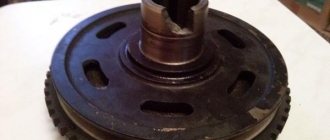
11. After unscrewing the two bolts, remove the rear main bearing cover. Two thrust half-rings are installed in the grooves of the rear crankshaft support. The front ring A is steel-aluminum, and the rear ring B is metal-ceramic. The rings can be removed by pressing on their ends with a thin screwdriver.
12. Unscrew the bolts of the remaining main bearing caps, keeping the crankshaft from falling. We remove the covers one by one and remove the crankshaft from the VAZ 2107 engine crankcase. All cover liners (except for the third) installed in the main bearing beds have a groove. The main bearing caps have marks corresponding to their serial number (counting from the crankshaft toe), facing the left side of the VAZ 2107 cylinder block. The fifth cover has two marks spaced at the edges.
13. To replace, remove the crankshaft main bearing shells from the cylinder block and covers.
Note:
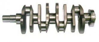
If there are any cracks on the journals or cheeks, the crankshaft of the VAZ 2107 must be replaced.
14. Using a micrometer, measure the diameters of the crankshaft main and connecting rod journals and compare them with the data given in the table.
If wear or out-of-roundness is more than 0.03 mm, then the crankshaft journals must be ground in a specialized workshop where the necessary equipment is available (the axial runout of the main surfaces of the crankshaft must also be checked there). After grinding the crankshaft, we re-measure the diameters of the crankshaft journals to determine the repair size of the liners. Do-it-yourself installation of the crankshaft on a VAZ 2107
1. We wash the crankshaft in kerosene and blow through its internal cavities with compressed air. We install new crankshaft main bearing shells of nominal or repair size. On the outer cylindrical surface of the liners there are numbers stamped indicating the repair size: 025 - the first repair, for the crankshaft journal, reduced in diameter by 0.25 mm. Accordingly, for the second, third and fourth repair sizes the values will be: 050, 075, 100.
It is easy to distinguish connecting rod bearings from main bearings. The upper main bearings (except for the middle one) have annular grooves. In addition, the middle support crankshaft bearings are wider than the others. The crankshaft connecting rod bearings are all identical and interchangeable; the diameter of the connecting rod bearings is less than the diameter of the main bearings. To increase the contact area, there are no annular grooves on the connecting rod bearings.
2. We install thrust half-rings in the grooves of the fifth main bearing bed with grooves towards the crankshaft. Half rings are made of normal thickness (2.310-2.360 mm) and increased thickness (2.437-2.487 mm).
3. We check the axial clearance between the thrust half-rings and the thrust surfaces of the crankshaft, which should be in the range of 0.06-0.26 mm. If the gap exceeds the maximum permissible (0.35 mm), replace the thrust half-rings with new ones, increased by 0.127 mm.
4. Lubricate the crankshaft connecting rod and main journals with engine oil and install the crankshaft into the cylinder block.
Replacing crankshaft half rings
The crank support of the connecting rods, which creates torque, is not a flat or single piece, but several individual elements connected together. Due to this design, strong axial play appears inside the block, which can disrupt the operation of the motor. To eliminate it and stabilize the rotation, the designers came up with the idea of locking the device with special sliding bearings. The crankshaft half rings , as they are called, take on heavy loads, so they wear out soon.
Purpose, where they are located
Half rings or crescents, washers - they are called differently, they have a special purpose. They keep the crankshaft from axial displacement or longitudinal play. Essentially, these are special type bearings that establish the required clearance.
In a classic 4-cylinder engine, the crankshaft has a minimum of 5 bearing points or journals. Their contact area is quite large. This increases the friction force, which becomes even greater when the cheeks touch the supports. To minimize structural imbalance, the necks are made wider than the supports. But such a solution causes longitudinal play, which is a priori unacceptable, since the crankshaft parts begin to fail prematurely as a result.
Metal stoppers in the shape of a crescent are precisely the most effective solution that allows you to maintain the classic design, while eliminating axial displacement. This bearing differs from the standard liner in the presence of side stops or shoulders. The surfaces of the areas where the crankshaft comes into contact with them are also modified. In particular, they are made to fit a ring.
To reduce longitudinal play, washers are also suitable - one-piece rings that are installed strictly in a place specially designed for them. However, such locking elements are rarely used, since lock bearings adhere more tightly to surfaces, wear out more evenly, and are easier to install and remove. And the most important thing is that the washer is installed only on the rear main journal, and the crescents can be placed on any journal.
Structurally, the locking element is very simple. The base is made of solid bronze or steel material, on which, in some cases, an anti-friction protective layer is applied. There must be grooves or recesses for free passage of lubricant, as well as special pins that enhance fixation.
Thrust half rings are placed between the block support and the crankshaft brushes. Here they keep it from axial movement and play to the maximum extent possible. Installed on various necks. For example, in the VAZ-2106 - on the 5th main bearing, which is the first on the flywheel side. In general, according to this scheme:
- anterior - on the third or one of the central necks;
- posterior - on the back neck.
Either 2 or 4 half rings are used. If two are used, then they are placed in the recesses of the lower yoke cover. And if there are four - an upper support and a removable yoke (like on tractor engines). There are also power units with one crankshaft locking crescent or just a washer.
Functions and design of the camshaft
The VAZ 2107 camshaft (injector and carburetor) synchronizes the operation of the intake and exhaust valves with the position of the pistons in the engine cylinders. It opens the exhaust valves to release exhaust gases and the intake valves to fill the combustion chambers with an air-fuel mixture. The “seven” uses an engine layout with an overhead camshaft. This reduces the cost of construction and makes the maintenance process easier. The VAZ 2107 camshaft is connected to the engine crankshaft via a chain driven by a sprocket. As the camshaft rotates, the cams located on it press on the rocker and open (close) the valves at the right moment. The camshaft bearing journals rotate in the bearings of the “bed” installed in the engine head. Lubricant from the oil pump is supplied to them through the oil channels, so the condition of the camshaft affects the pressure in the engine lubrication system.
Camshaft faults
The main reason for checking the condition of the VAZ 2107 camshaft is the appearance of a characteristic knocking sound in the head while the engine is running. There may be several reasons:
- wear of camshaft cams;
- wear of camshaft support bearings or bed journals;
- deformation of the part as a result of overheating;
- the appearance of a crack on the support of the part;
- camshaft fracture;
- lack of oil or low pressure in the engine lubrication system;
- clogged oil channels
- low quality oil.
If the camshaft wears out or cracks, the part must be replaced with a new one. But first, it’s worth localizing the problem by removing the camshaft and inspecting its condition.
Fault diagnosis
Diagnosis of thrust parts is usually carried out after the 120,000th mileage of the engine. It consists of three steps.
- Visually inspect the internal combustion engine for oil leaks. If they are present, this is already an indirect sign. A poorly fixed crankshaft squeezes out the oil seal responsible for sealing. And the lubricant begins to flow out.
- Loosen the generator pulley with a mounting blade, resting one end of the tool against the body. The permissible axial play should not exceed 0.35 mm.
- Press the clutch pedal from inside the car. The crankshaft should not move forward. Otherwise, this is the surest sign of breakage of the thrust half-rings.
Axial movements of the crankshaft cause a loud, irregular knock, which experienced mechanics can distinguish.
Removal instructions
With the clutch disengaged, the crankshaft can be easily turned with a wrench.
To carry out the removal procedure, it is necessary to secure the shaft from turning.
There are special devices that are bolted to the pulley into the technological holes, preventing the shaft from turning. If there is no such device, then you need to install supports under the wheels and place the car on the fourth. You can also secure the crankshaft flywheel by inserting a long screwdriver or pry bar between its teeth.
Causes of wear, loss of half rings
It happens that when disassembling the engine, thrust washers are found in the crankcase pan. On the crankshaft, in the place where these parts should be located, wear is noticeable. Parts may fall out due to the following:
- recently carried out a major overhaul of the engine, without following the sequence of installation of the elements;
- after assembly, the main support covers are mixed up;
- The rear semi-ring is severely worn out because the metal-ceramic and steel-aluminum types of parts were installed incorrectly in places - this also happens when the quality of the thrust half-moons is poor, the material of which does not correspond to the technical documentation.
In general, the main wear of the half rings occurs when the clutch is squeezed out. Especially on a cold engine in winter and sitting for a long time under a traffic light with the clutch depressed. Thus, the cause of wear may be due to insufficient qualifications of the car driver.
The fact is that squeezing the clutch transfers the entire load from the fork to the corresponding crankshaft half-ring. There are even drivers with extensive experience who constantly keep their foot on the clutch. But for this there is a special platform where the left leg should rest.
Required tools + consumables
Mandatory tools that will be needed during the work:
- set of wrenches and sockets;
- set of screwdrivers;
- torque wrench for proper tightening of bolts;
- a flat feeler gauge for measuring axial play, or even better, a special indicator with a scale;
- clean rag.
- new half rings;
- pan gasket;
- sealant.
Replacing the support half-rings is usually accompanied by updating the engine oil, installing a new oil pan gasket and other related operations.
There are three sizes of thrust washers available on the market. Standard at 2.31, first repair and second repair (2.437 and 2.56, respectively). Therefore, you must first clarify which dimensions are suitable for your car’s engine. Typically, parts of standard or nominal sizes are installed on new or slightly worn motors. And repair ones, with increased thickness - to compensate for worn parts of the support and shaft, that is, for old and fairly worn-out internal combustion engines.
The importance of fine tuning
It must be taken into account that do-it-yourself adjustment of VAZ 2107 injector valves is available to all car enthusiasts, even in garage conditions, with a minimum set of tools. Often the operation is carried out on a hot engine, although it is preferable to do it “on a cold one”. The result will be more accurate readings.
It is important to know that adjusting the VAZ 2107 valves (injector) will require purchasing two types of probes: 0.15 mm for monitoring a cold engine and 0.20 mm for monitoring a hot engine.
Probes of different sizes are available for sale. It is preferable to use wide ones, as they are more comfortable to use, and they are often sold in pairs. As a result of proper setup and adjustment, the following results can be achieved:
- valve timing will work most accurately;
- the working cylinders will become fully filled with the air-fuel mixture;
- the mixture will burn as completely as possible;
- high-quality blowing of the empty cylinders will be ensured.
Correctly set valve clearance of the VAZ 2107 (injector) will result in cleaner operation of the internal combustion engine, possible knocks from the engine compartment will disappear, and the service life of the vehicle will significantly increase. This factor is a consequence of the lack of impact of the camshaft cam on the rocker (drive lever) or valve axis. Thus, these parts will be able to last much longer if the adjustment gaps are clearly ensured.
However, reducing clearances is considered more problematic for engine operation. With this position, the chance of the valve burning out increases, because it does not have time to install itself in the seat of the block head. Aggressive exhaust gas from the combustion chamber is directed through the resulting cracks. Its temperature during the explosion phase reaches 2000 C, which leads to burning of the edges of the exhaust valve. Valve seals are also negatively affected due to overheating, which is accompanied by increased oil consumption and contamination by combustion products.
The importance of adjustment is obvious for the performance and increase in the service life of the car. Control must be carried out depending on the degree of operation after 10-15 thousand kilometers.
Replacement process
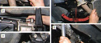
To correctly carry out the replacement, you must act strictly according to the instructions, performing the steps sequentially:
- put the car on a pit or overpass, stop the wheels;
- remove the engine protection;
- drain the engine oil;
- unscrew the bolts and remove the crankcase pan along with the gasket - it is held on by 16 fasteners;
- pull out the middle main bearing cover - it is secured with bolts;
- install new washers, lubricated with a small amount of engine oil, with grooves towards the thrust surfaces of the crankshaft, pushing out the old half rings with them;
- put the cover back, tighten with a torque wrench the torque corresponding to this unit (given in the technical literature for each engine);
- check the axial clearance of the shaft with a flat feeler gauge - it should not exceed 0.06-0.26 mm.
To facilitate installation, you need to move the crankshaft with a screwdriver and at the same time rest the new half-rings with their ends against the old parts. This way you can squeeze them out faster, and the spare parts of the repair kit will fit into place.
When installing the half rings, their slots or recesses should face inward, towards the crankshaft.
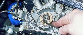
Replacing oil seals
If the crankshaft oil seals have been squeezed out due to axial displacement, both will have to be replaced with new ones. One is installed on the pulley side, the second on the flywheel. It is extremely important to replace the first seal, which is on the timing side. Because oil will leak out and get on the belt. And this is a serious risk of slipping one or several teeth or even worse - breaking. What will happen is known: it will be necessary to change the valves, since the rods will be bent or broken when they meet the pistons.
The front oil seal can be replaced from the gas distribution mechanism side. It will be necessary to remove the protective casing, belt, and crankshaft toothed pulley. Then remove the cuff and install a new one. But the rear oil seal is more difficult to change. It is necessary to dismantle the gearbox and clutch. After removing the cuff, thoroughly clean the seat, and only then install a new product.
It is imperative to make sure that the half rings are assembled and installed correctly at the final stage. To do this, the crankshaft is turned by hand - rotation should continue automatically (0.5 turns), be smooth, without any jamming.