02/26/2022 1,950 Alarms
Author: Victor
The sequence of connecting the central lock to the alarm depends on its type: pneumatic, with constant or variable polarity. However, in order to correctly connect the central locking system using any of these schemes, you first need to prepare a lamp probe. To search for circuits on cars of recent years, it is better to use a voltmeter so as not to damage the wiring.
[Hide]
Let's make friends with central locking and alarm system
According to reviews from car owners, connecting the alarm system to the central locking is a responsible and at the same time troublesome task. When performing this operation, it is easy to make a mistake, and the consequences can be very negative. In the best case, the central locking control unit will fail (300 - 400 rubles), but we do not consider what will happen in the worst case. Not surprisingly, the likelihood of making a mistake is very high: alarms come in different types, and lock control units can also be of different types. We will look at all this in detail further, but still, when making connections, rely on common sense. If you're not sure, don't connect.
To carry out the work discussed below, you will need a 12-volt control lamp. It is known that such probes cannot be used in modern cars. But we will short-circuit the signal cable to ground or positive, and the resistance of the diode probe is too high for this. If you follow the instructions, you won’t be able to “burn” anything. We will simply apply negative or positive voltage to the control cord.
Types of central locking control units
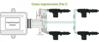
The central locking system is simple - a single unit controls electromagnets installed in the doors. This unit itself can be located in the front door (Honda cars), but more often it is installed under the hood. The figure shows the appearance of the block used in VAZ cars:
There are various wires going to the connector, including power and ground. But there are always two wires that are signal.
Classification of central locking control units:
- Negative impulse control. We close one of the signal wires to ground - the locks are forcibly locked. We short the second wire to ground - they open;
- Positive impulse management. Same as “1”, but you need to apply “+12 V” to each wire;
- Variable polarity control. One of the signal contacts needs to be shorted to ground, “+12 V” must be applied to the second, and then the locks will open. If the polarity is changed, they will close. But when voltage (0 or 12 V) is applied to each contact separately, nothing happens.
Before carrying out work, it would be a good idea to find out what type of control the unit uses. For case “1”, the control unit is connected to ground and the wires are checked one by one. If a positive impulse is needed (case “2”), the control is hooked up to the “plus”. Using this method you will find both signal pins. For the third case, everything will be somewhat more complicated.
So, are you sure that variable polarity control is being used? To search for signal wiring, perform the following steps:
- We connect the LED-based probe to ground. When closing the locks, the diode on one of the “important” contacts of the connector should light up, and on the second one, it should go out (or not light up all the time);
- Connect the probe to positive voltage. On the first of the found contacts, the LED lights up, but only at the moment the lock is opened. On the second at this moment it goes out briefly or does not light up all the time;
- It should be noted that the test is performed only during the unlocking or closing process. The rest of the time the probe can react as desired.
We hope the principle is clear. It will take a long time to search; it’s easier to immediately find the connector diagram for the control unit.
Note: an alarm system equipped with signal outputs without a relay is not connected to the lock of the last class considered.
This is impossible in principle. You can independently make a block containing a relay and all the necessary “piping”. But we do not mention this option.
Connecting the signaling to the central locking system
First of all, let’s answer the question: why do we connect an alarm to the lock, and what do we want to get as a result? The central locking system, as it was found out, can be controlled using two signal cables. This will be used further: the automation will have the ability to change the state of the locks, unlocking or closing them as needed. Each alarm has outputs designed to control the central locking system. There is an output for opening and locking.
Central locking is controlled by constant polarity
So, we are looking at a type of lock, designated in the first chapter by the number “1”. Signaling outputs intended for central locking can be power or signal. In the first case, we are talking about an unlocking relay and a closing relay, and then the connection is made according to the diagram:
The green cable coming from the alarm connector is responsible for locking (LOCK), the white cable is for opening, and therefore the top node in the diagram is the locking relay. The normally open contacts here are connected to ground, the common contacts are connected to the central locking signal wires. How to find and recognize these wires was discussed above.
It is important to know the following. The wires are not cut off from the connector of the central locking unit; the white and green cables indicated in the diagram are simply connected to them. By the way, the alarm outputs may not be “relay legs”, but rather low-current signal outputs. If negative polarity is used, then everything is clear, but if it is “combined”, install diodes (“arrow” should go to the signal connector).
We discussed above how to connect a lock controlled by a negative pulse. If we talk about another type of central locking system, numbered “2”, the diagram will not differ much:
Unlike the first option, the normally open contacts here are connected to the “plus” and not to ground. The top lever is a locking lever, the bottom one is responsible for opening. And just as in the first case, signal pins can be used instead of a relay. But then, the diodes should “point” to the central locking connector.
Central locking controlled by variable polarity
A lock controlled by alternating polarity is the most difficult to connect. We immediately present a diagram from which it is clear that the alarm unit must contain a relay (the top relay here is a locking one):
Two wires that previously went from the central lock control unit connector to the actuators should go to the alarm connector (to the “middle” contacts). The main thing is not to confuse them with each other. The operation of the upper relay should lead to closing, and not vice versa.
Let us list the features of the third scheme:
- To wire “1.” at the moment of closing there is a “plus”, on the second wire there is a “minus”;
- At the moment of forced unlocking, everything is the other way around: wire “1.” turns out to be on ground, on wire “2.” goes “+12 V”;
- After installation, with the BU connector central locking wire “1.” and 2." no longer in contact. This is the main drawback (the standard connection has to be disconnected).
Note that central locking control using the “alternating polarity” method is used only in cars from the USA. And even then, not in all of them. And alarm systems equipped not with relays, but with low-current control outputs, are now practically not produced. So, there is a high probability of connecting everything as it should. We wish you success.
FakeHeader
Comments 31
Hello. Can you please tell me how and where to connect the power window closers?
the green wire is responsible for the impulse for the power window module
Why is it necessary to install a relay on the trunk? Why can’t you put a plus from the battery and a minus from the block onto the activator?
because there is a low-current control on the block, it will just burn out, that’s all, so that it doesn’t burn out, they put a relay
Damn, I read the first comments and my brain exploded, but if you understand the essence like this, then neither the alarm nor the immo or anything else will save the car from real thieves. Why all this controversy? Central locking is a really convenient thing, it won’t affect safety in any way, an experienced thief will open your trough in a couple of minutes, but an inexperienced one will stupidly take out the glass and steal what he can, so now put bars on the windows? The original system can also glitch, but the signaling system was correctly noted, this is not so much protection as a way of attracting attention, not effective as practice shows, because everyone is sick of empty alarms and no one reacts anymore. By the way, a fun fact: for about 3 years now, if not more, I haven’t heard a single car screaming in the yard at night. The time has probably passed when it was fashionable and the car was screaming every leaf that fell on it.
what's the use of it? it doesn’t guard, it’s probably broken by a code grabber. a waste of money
How can you not understand that this is from the budget segment, for people who lock their car with a key and there has never been any security there and never will be, and they don’t give a damn about whether it is protected there or not, they are just tired of poking around with the key. that's what it's for
and it is not yet known when it will glitch or burn the locks, because only God and the Chinese know who wrote the software for it and how
No matter how crookedly it was written there, it will be more reliable than the electrician Vasya, who will write the software. The Chinese are leaders in this area. Tell me what is not China now?)
I beg you, you apparently haven’t worked with such equipment, I have, it would be better if our programmers wrote it. You don’t know how Chinese programmers work? Like bad doctors, they treat one thing and cripple another, they corrected 1 mistake, introduced 3 new ones. This applies even to large factories, everyone is guilty of this.
There is a good product. There is a cheap one in which everything speaks for itself, like here. for 500 rub. There are other blocks for 9 thousand. Can you feel the difference? The quality is also felt. I can’t say anything about the Chinese doctors, my father attended a couple of sessions, and it helped him a lot, he visited our doctors, and he was no longer alive.
They can ruin even a good product, it’s been verified. For 9 thousand there is already an alarm system with auto start, nothing like a simple central locking system. I was not talking about Chinese doctors, but about crappy doctors. At least read the text carefully. The fact that my father passed away after visiting our doctors does not necessarily mean that the doctors are to blame; the reason could be the incurability of the disease, such as CANCER, for example.
Don't be funny ok? My neighbor died because the doctors made an incorrect diagnosis. Afterwards, treatment with various medications was prescribed, which in turn brought him to the next world.
Volkswagen central locking, pneumatic
In fact, we have not considered another type of central locking system - pneumatic or vacuum locks. They are controlled using one cable, not two. The control wire can be found in the trunk (near the compressor), under the rear seat, and so on. When opening, there will be a “plus” on the wire; when closing, it is connected to ground. The found control cord will have to be cut. Both parts of the cord are connected to the signaling (details are discussed below).
Here is an example of connecting an alarm:
The same in the form of letters:
- Unlocking NR – to “+12 V”;
- Closing HP - to ground;
- Unlocking NC - to that part of the cord that goes to the central lock control unit;
- Closing NC - to the “common” lobe of the unlocking relay;
- The “common” petal of the closing relay is to the second half of the cord (to the actuators).
We hope no questions arise here. But still, just in case, we will open the comments.
In conclusion, we note and emphasize once again that any installation work is carried out with the negative terminal disconnected.
We are talking about the battery terminal that powers the electrical network. When laying a new cable, use heat-resistant insulating tubes or electrical tape. All equipment installed in the car is located in an aggressive environment. This must be remembered.
What to find out before installation
We mentioned such a concept as “control pulse duration”. The pulse itself can be generated by an alarm (otherwise, why would we connect it). Of course, the duration can be adjusted. But the limits of regulation may not be appropriate. Then, it remains to state a fact: the equipment (standard and installed) is incompatible with each other. There is nothing more to add here.
There is a radical method: actuators are connected to relay contacts installed in the alarm unit. Look how many pins a modern actuator has:
Door lock actuator
Most likely, there will be two power wires, and then there will be no difficulties. But this connection option is fraught with a hidden danger: when making changes to the power part, any circuit must be equipped with a fuse. But it is difficult to correctly determine the ratings of these fuses. So, we are not considering the last option. It is not recommended.
Connection Schemes for Central Locking to Alarm System
Similar articles:.
When the locks are unlocked, it will have a positive charge, and when locked, it will have a negative charge. The unit in question can be implemented not only into a standard system with minus or plus control, but also into a central locking system with a vacuum drive. Connecting and checking central locking and alarm systems at home.
For the first case, you can find a way out using a control light.
The relay indicated in the diagram above is responsible for locking.
You can connect the trunk using an additional 4-pin relay. If the probe light goes out when closing or opening, and then lights up again, then we change the probe to minus and poke into the same wire and again control the central lock. Connection to the central locking with negative contacts, as you might guess, is carried out through the supply of negative voltage to them. But we do not mention this option.
Comments and reviews
Lock with a positive impulse mechanism Similar to the first type of central lock, this device is also controlled via two wires, only in this case a positive supply will be required to operate. The easiest way in this case is to connect an alarm with low-current negative outputs, since it is carried out directly through the connection to the control wires of the lock. The remaining wires are connected for light signaling, glass closers, etc. The specificity of this system is that the cables found control the door mechanism drive. K37 - central locking control unit.
Initially, the electronic part of the unit was contained in one housing with connectors. What difficulties may arise and how to overcome them The connection process is quite labor-intensive, so users may encounter some problems: The problem of choice with a wide variety of security systems.
The current consumption of a conventional electric central locking drive can reach 5A at its peak. It takes two people to determine the malfunction - one will send signals from the remote control to lock and unlock the central locking system.
This wire is located either near the compressor in the trunk or under the rear seat, or comes from the central locking control button.
In some models of security systems, low-current signal channels are used as outputs rather than relay contact components. This leads to the unlocking of the locking devices. In auto stores you can choose wires of various diameters, colors and lengths. ✅How to connect central locking to any car?
Repair
In fact, the central lock tends to break not only due to frost. Activators often become unusable.
Activators are one of the important parts of the entire system. In addition to the fact that activators are performers, the driver's door activator is also a sensor. The fact is that the activator on the driver’s side sends a signal to the control unit when it is pressed and closes everything. There are often systems where, in order to lock everything, you need to press the driver's door lock button. This button is screwed to the activator. Based on this, the driver's door activator causes all activators to operate. Here you will need to disassemble the door and see if the button on the activator is pressed; if not, then raise the activator higher, and if the button is pressed but nothing happens, you need to change it.
Operating principle of central locking
The central locking unit is connected to all sensors and wires, therefore it is the main element of the security system; actuators are essentially a DC motor connected to a gearbox. The central locking is usually controlled using a two-way button with three contacts - one common and two normally open.
Types of central locking elements
The general connection diagram will look like this: the common outputs are connected to the control wires of the lock, the NC contacts and half of the relay coils are connected to the plus, the other half of the coils are connected to the main wiring. Two signal wires, white-brown and brown, come to the block from the passenger actuators. In idle mode they have little positive potential.
The control button in the cabin can be one on the driver's door or on the panel, or two on both front doors. When installing an alarm system, it is advisable to avoid interfering with the central locking control units. We are talking about contacts located in the middle. The current consumption of a conventional electric central locking drive can reach 5A at its peak. Recommendations: For self-installation, simple security systems with a minimum set of sensors are more suitable.
More articles from the Tuning section. The schematic diagram is taken from the Opel Astra F repair and operation manual. To connect to the central locking, you need to know what type of central locking is installed on your car. Drives equipped with switches, each with three contacts, are mounted on the car doors and in the luggage compartment lid. Alarm installation
Positive impulse lock
It is used to ensure the coordinated operation of all lock products.
Features of connecting the system to a lock with variable polarity In this case, the car alarm must be connected directly to the car's power wires, which are again looked for with a probe.
The remote control unit comes with instructions that allow you to connect the system in parallel with the standard central locking unit. We sit down with a probe to ground and poke at the wires coming out of the door. The probe should not be a diode, but with a light bulb, otherwise the minus may not be enough to control the central locking. The supply of light to the corresponding lights in the cabin depends on their signals.
After all the materials have been collected and all the introductory information has been read, you can begin the installation. But with such a scheme, the diode elements must point to the lock plug. The current scheme for connecting the central lock to the alarm system in this case provides for a direct connection to the power wires.
Before connecting the central lock to the alarm, by analogy with the previous type of lock, you need to cut into the control wire. I would like to warn you right away that the article does not claim to be the best instructions or installation method. Our task is to find the main lock block relay.
Signaling outputs intended for central locking can be power or signal. When unlocked, a positive charge is recorded on the control wire, and the device lamp lights up. Has 10 wires of different colors. If the probe light comes on when closing or opening, then this is one of the wires we need. If the alarm system has low-current positive outputs, then the connection is similar to the previous one, only place one side of the coils on the minus, not the plus.
This refers to elements with which you can unlock and close lock products. If the activator fails, you can easily replace it with a new one.
In most cases, if you manage to disassemble the central locking unit, there are two points, when a minus is applied to them, the doors are controlled. These wires are used to connect various electrical appliances, power tools and other machines and devices. Structurally, it consists of an electric motor and a metal or plastic gearbox. The security system wires do not have to be connected to the relay connectors; you can connect them to low-current signal terminals. Car alarm from Aliexpress - Connection diagram, operating logic, unpacking, review, test.
Self-installation
We carry out installation in stages. We leave the connection with the anti-theft agent for later, we will deal with it last. We start the work itself by installing the necessary elements and only then move on to the electrics.
First, remove the door trim. We also get rid of the panels between them and the thresholds below. The first to use is the control unit, which, in the old fashioned way, is recommended to be mounted in the lower left corner of the driver's door. In fact, you can choose the location yourself, the main thing is to remember that it should not interfere with the operation of other mechanisms, for example, window regulators.
Alternative installation location for the control unit
The next stage is the installation of engines. In the kit you will find four motors, one of them with four wires. We attach it to the driver's door, the remaining activators are also installed on the car door. If your vehicle does not have the required mounting holes, you will need to drill them with a drill.
Activator installation process
Now we are ready to start working with the wires. Scatter them around the cabin, as if outlining what will go where. Remember, we lay the wires in protective tubes, which will protect them from contact with moisture, dirt, and with each other. To perform this work, you can use the space under the front seats, the free space between the doors. If necessary, you can also drill a few holes. But do not forget that their diameter must be increased to match the size of the corrugation. Further connections are made according to the diagram. Everything here is purely individual and depends on the type of electric locks. Our main task is to bring them all to the control unit.
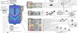
Electrical connection diagram
After this, you can return the battery to its previous state and perform the test. If connected correctly, there should be no problems. Remember that as soon as you return the negative terminal to its place, the locks will work automatically, so either do not close the doors or leave someone inside the car.
Connecting an alarm system to the central locking - the main difficulties of the procedure
Nowadays, motorists have the opportunity to choose any type of security system for their vehicle, focusing on their own needs and wishes.
But choosing the “best” alarm system is half the battle. It still needs to be properly mounted and connected to the central locking.
Specific connection points for the security device are selected depending on the following factors:
- type of alarm system purchased (without remote control or with one);
- model of the vehicle on which the system is planned to be installed;
- location of the main security mechanism (block).
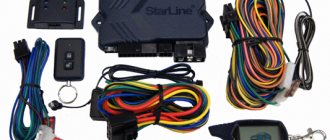
You can determine the connection points for an alarm with automatic start using the passport of the purchased device, a lamp probe or a voltmeter . In addition, you will need a vehicle wiring diagram. It is with its help that you can find the elements to which the alarm will be connected.
Before starting work, you need to decide on the type of central locking (CL) of your car. The most common types of central locks are:
- driven by positive impulse;
- controlled by negative impulse;
- with variable polarity.
How to attach a keychain?
After installing the components of the complex, the radio transmitter or remote control is linked. This device is designed to control the system, so the binding will allow you to configure the basic functions of the device. The binding procedure is performed differently depending on the features and model of the alarm. First, the microprocessor module must be put into emergency mode, in which system maintenance is carried out.
This mode is activated by entering a special combination with the Valet or Override key. Depending on the model and manufacturer, this combination will be different. Before completing the task, the security mode of the alarm is turned off. The key is clicked several times, after which the ignition system is activated. The entry into the setup mode will be indicated by sound pulses of the siren or a melodic signal from the radio receiver.
Then the consumer clicks on several keys on the transceiver, the button numbers are noted in the service manual. The binding will be indicated by sound pulses. The pager is connected and the microprocessor module remembers it. The procedure for setting up the remaining remote controls is performed in the same way.
Mikhail Autoinstructor made a video with a complete description of the process of reprogramming radio transmitters of security systems.
Connecting an alarm to the central locking system with a negative and positive pulse
In this case, when a minus is applied to a pair of lock wires, they close or open. Finding such wires is relatively easy using a probe (lamp). You should alternately close the wiring that comes out of the car doors on the driver’s side. As soon as the right pair of wires is found (the door opens or closes), the problem can be considered solved.
In those cases where it was not possible to find the wires, you will have to “dig” into the central locking unit. You will need to find a special relay in it that is responsible for closing/opening the doors, and then solder the security system wiring into it.
Working with a lock controlled by a “plus” pulse is similar to the scheme described above. Only the required pair of wires in this case, as you yourself understand, will have a plus polarity. In other words, positive wires should come from the alarm.
The connection diagrams for the voiced types of central locking with a built-in relay will therefore be as follows:
- “Negative” pulse: NC (normally closed) contacts are not needed, NR (normally open) contacts are connected to the “minus”, common contacts go to the control wires.
- “Positive” impulse: open contacts are connected to positive, closed contacts are not used, common ones, as in the previous version, are connected to the found control wiring.
Starline does not open or close doors using the key fob: main problems and solutions
The Starline alarm system is a reliable system that protects the car from theft, but at the same time, problems may arise with opening the doors using the key fob. They may be due to a simple decrease in battery charge or incorrect signal recognition by the system. But in some cases the situation is more serious and there are several ways to solve the problem.
Problem with opening doors after autostart
After using the autostart function, the Starline alarm system can block the automatic opening of doors even if the system is disarmed. In this situation, you have to use the key and open the car manually.
The problem may be caused by incorrect connection to the central locking control circuits during installation. To solve, it is necessary to reconnect 2 alarm wires responsible for controlling the lock, provided that there are no problems with the circuits responsible for the operation of the seat belt.
If the seat belt cover in the driver's seat is closed, the doors will not open.
It is also necessary to take into account the indicators on the key fob - unlocked/closed lock. This indication indicates arming or disarming, but not unlocking or locking the door.
None of the alarm systems, including Starline, have the ability to control the process of opening and closing the central lock and simultaneously display the operation on the lock screen.
Problems with locking the car with the key fob
The Starline alarm system may have problems locking the car. At the same time, the warning system operates normally, but the doors remain open. The reason may be a simple disconnection of the plug under the driver's seat.
Therefore, the alarm system cannot recognize the signal from the limit switch about the door opening, which entails the automatic installation of the car in the security mode within 30 seconds. The fuses on the contacts in the alarm unit may also be damaged, preventing the signal from being sent.
Diagnosis and solution to this problem can be achieved in the following ways:
- Without removing the key from the ignition switch, you must open the driver's door and then remove the key. Then slam the door and put it in security mode.
- Disconnect and reconnect the negative terminal from the battery.
- Pull the handbrake, remove the key, open the driver's door, press the central locking button to close all other doors, close the driver's door and press the lock button on the key fob.
If after these manipulations the problem is not solved, then you need to contact the Starline service center for advice and a possible replacement of the system during warranty service.
Features of connecting the system to a lock with variable polarity
In this case, the car alarm must be connected directly to the car's power wires, which are again looked for with a probe. First, use it to find the negative power wire (the device should be connected to the positive, and then press the corresponding button on the alarm, determining the required wire). They look for another wire (power) in the same way.
After this, you will need to cut the identified power wires, purchase two relays if we are talking about a car alarm with low-current type outputs, and connect according to the diagram below:
- general contacts - to the wires coming from the driver's doors;
- normally closed contacts - to those wires that go to the lock button or to the central locking unit;
- normally open contacts – to the “plus”.
You have successfully completed the procedure for connecting the alarm to the central locking!
Blocking via CAN bus
An engine blocking relay is the simplest and most common way to prevent unauthorized engine starting. Regardless of whether the relay is built into the central alarm unit itself or an external one is installed, the essence of its operation is the same. As long as no current flows in its winding (cars use relays with low-current windings, so they can be directly connected to the alarm output channels), the relay armature (common contact, 30) is electrically connected to a normally closed contact (NC, 88 or 87a).
it will remain closed forever.2. When blocked by a normally open contact, every time you turn on the ignition on a disarmed car, the contacts close, opening when the ignition is turned off. The relay wears out, but when the central alarm unit is turned off, the protected circuit will remain open.
Which circuits can be reliably protected using relay interlocking? The most useless thing is the starter interlock relay, because on many cars the starter is turned on forcibly by closing the contacts of the retractor relay under the hood with a screwdriver or key. In addition, such a lock is useless during a robbery: by taking away your already running car, the robber can safely drive away.
It will also not allow you to start the engine, but if you have access to the engine compartment, it will do the same, using a temporary wire. Without a reliable additional hood lock, such a lock will not stop the thief for long.
The resistance of resistor R1 must be equal to the resistance of the crankshaft position sensor winding. In this case, when the blocking relay is triggered, a “trick” is connected to the inputs of the injection ECU, and instead of recording the error, the ECU will not “see” the rotation of the crankshaft.
The blocking relay switching diagrams indicate a diode connected in parallel with the winding. In some relays it is even built in from the start. What is it for? The fact is that the relay winding has a certain inductance, and when the power is turned off, a sharp surge of voltage occurs in it with the polarity reversed to the original one.
However, on modern cars there is an even more elegant way to block the engine from starting. In this case, there are no physically broken circuits, and there are no additional connections: it is enough for the alarm to have a connection with the car’s CAN bus.
The essence of such blocking is that when an alarm is triggered, the alarm transmits a blocking command via the bus and repeats it all the time until the alarm goes off. And until the thief turns off the central unit, attempts to start the engine will be useless. If we take into account that with proper installation of the central unit, half of the interior will need to be disassembled to remove it, then this method is clearly the leader in terms of efficiency.
Preparing to connect a car alarm to the central locking
Connecting an alarm system requires studying: standard locking devices installed. The central locking of the car is a system of electromechanical operating principle. Electronic car theft protection and central locking require coordinated work. The central locking assembly consists of the following components:
- The control module, which is responsible for the synchronous operation of all locks, is connected to the electronic protection of the car against theft using the provided connectors.
- Buttons, sensors, connecting the alarm system to the central locking system.
- Central locking drives are available in electric and pneumatic versions. Car alarms are often connected to power locks.
Connecting electronic security to the central locking of the car is carried out with a preliminary search for access points. Only a specialist knowledgeable in electrical engineering can find access points. The points are indicated in the diagrams: instructions for installing car alarms; cars.
On passenger vehicles, control modules, with vehicle protection connection points, are located in the places designated for them. Car alarms are connected to the central locking system via the interior wiring switching unit. Different brands have their own locations, but specialists know them.
It is common to place blocks at the bottom of the front panel. On older brands of vehicles they are located to the left of the steering column. On new Russian models, the blocks are located to the right of the gas pedal.
First stage
Removing door panels.
First you need to remove the door trim and dust curtains from each door. Before doing this, you should disconnect the terminals from the battery for your own safety.
Removing the door panels is a fairly simple task - unscrew the 4 screws under the shelf. Now you need to remove the handle. Then you can carefully remove the upholstery. Think about the three latches located on the edge of the lock. The door has a plastic screw that needs to be unscrewed. Then remove the screws located in the trim under the steering wheel (the first on the left and the other on the right side).
Selecting a location for installation.
To choose a suitable location for the central locking for installation, you need to take into account the location of the insides of the window regulators. It is possible that you will need to make a separate bracket for mounting
Experienced craftsmen suggest that the lower left corner is the best place for installation, because when lowering the glass, the latter will not touch the lock and interfere with its operation.
Installation of the activator.
Lock activators are installed separately on each door. To do this, you need to drill additional holes and secure them with self-tapping screws. We do the same installation for each door.
Attaching the activator to the lock rod.
Each activator from the installation kit must be secured to the door with clamps. Very often, the central lock has a large force that the activator must apply to open the door. Since the stroke of the actuator rod is greater than that of the lock rod, it is necessary to align the center of the stroke of both rods.
Further from the activators, we install clamps on the rods of the manual lock block. This work must be done with each individual car door. When connecting actuators, you need to check the wiring for current conductivity.
If the hole in the central locking rod is larger than necessary, you can use a plastic bushing that will reduce its size to the required size.
Pulling wires.
The four wires that go from each activator (two to it, and two to the car body) can be attached using plastic clamps. This work is performed individually for each individual vehicle. You can use existing holes or drill your own. It is not recommended to lay wires at the bottom of the door, where moisture most often accumulates.
In the problem area of the gasket - the opening between the body and the car door - it is better to use a rubber tube through it, which will protect the wiring from kinks and chafing.
The video shows the installation of central locking on a car:
Basic principles of connecting the alarm system to the central locking
There are options for connecting electronic anti-theft protection to the central locking system. On car alarm diagrams, the contacts used by the relay in the car are indicated.
Methods for connecting car alarms to central locks:
- Positive impulses.
- Negative impulses.
- Alternating polarity.
Below we present the connection of the alarm system to the central locking system.
Positive impulses
Connecting a car alarm to the central locking of a car with positive impulses is done in two ways:
- (A) is used when the central locking is controlled by an electronic module.
- (B) – when controlling internal drives.
The use of circuit (A) when connecting the electronic protection of a car is typical for the following brands: General Motors; Volkswagen Passat; Renault; Kreisler; parts of BMW, Ford models.
The essence of connecting the central locking system with a car alarm is to apply a pulse - 1 s to the control wires. The control module is triggered. By connecting the contact of a multimeter or “tester” to the positive terminal of the car battery, the wires of the door bundle are pierced one by one with a free probe. Electric locks are activated when the desired wire is punctured.
The procedure is performed by qualified specialists. Connecting an alarm system using this scheme simulates the closing and opening of locks using buttons.
By connecting electronic anti-theft protection - circuit (B), we achieve control of the central locking drive with positive potentials. The contact group of the drive is connected to the contacts of the machine alarm relay. The pulse duration is set to 4 s. – drive response time. Power is supplied through the fuse.
Negative impulses
Negative central locking control is widespread in many brands of cars; connecting car alarms is typical for passenger vehicles: Opel; Toyota; Honda; Fiat; Volvo; Citroen; parts of BMW models; VAZ 2111.
The central locking is controlled by applying a short negative pulse – 1 s – to the control wires from the vehicle’s electronic protection. The car alarm is connected according to the previous diagram (A). The difference is that wires are connected to the contacts of the alarm relay, supplying a negative pulse of 1 and 4 s in length to the central locking system.
A clear example of connecting a car alarm to the central locking with a negative pulse is the VAZ 2111.
Alternating polarity
The third type of central locking control for electronic vehicle theft protection is the alternate supply of positive and negative pulses to the drives. More often observed in cars manufactured in the USA between 1990 and 2000. 3 schemes were proposed:
- Power buttons;
- Central locking control module;
- Electric drives.
The first scheme, most often found in cars manufactured in the USA between 1990 and 2000, is based on the use of door buttons. The door buttons are connected to the contacts of the electronic protection relay. Turning protection on and off copies blocking and unlocking with buttons. The corresponding impulses - positive or negative - are sent to the wires of the buttons that operate to open and close the alarm. Power is supplied through a fuse designed for a current value of 10 to 15 A.
According to the second scheme, the alarm connection is realized through the central locking control module. The electronic protection wires on the vehicle are attached to the break in the power conductors of the drives. The installer must have a good understanding of alarm and central locking circuits.
The third reversible connection scheme is based on sending signals from the car alarm key fob to the car's central locking. The pulses are supplied through the machine alarm relay, which changes polarity with a period of 1 s.
When connecting electronic car theft protection to the central locking, difficulties arise. To eliminate negativity in the process of connecting nodes, you should stock up on diagrams, tools, and devices when connecting the alarm system to the central locking system. It is advisable to read on the forums about possible difficulties when performing connection operations into the system.
Many car alarms are connected to central locking systems. Modern alarm systems do not care what drives are used in the locks. Central locking is controlled by positive, negative pulses, as well as alternating polarity, transmitted by car alarms.
1st type: central locking controlled by negative impulse
Simply put, there are two wires, when a minus is applied to which the doors are locked or unlocked. We sit down with a probe to ground and poke at the wires coming out of the door (the probe should not be a diode, but with a light bulb, otherwise the minus may not be enough to control the central locking). When you hit the right wire, the doors will close or open. Here they are – the wires we need! Be sure to check that these two wires work even when the driver's door is closed. If you cannot find the wires from the door, but are absolutely sure that your car has a central lock controlled by minus, then you need to look for wires in other places.
Where, for example, is the central locking unit located in your car? Open and close doors using the remote control. or using the central locking control button and listen to where the relays click. These relays are located in the central locking unit. See what this block represents? If it is not difficult to disassemble, disassemble it. You see - there is a stick(s) there. Try applying negatives to the relay legs with a probe. In most cases, if you manage to disassemble the central locking unit, there are two points, when a minus is applied to them, the doors are controlled. This is where you will need to solder the wires from the alarm.
Another place to look for wires that control the central locking is the driver's door (in many Hondas, by the way, the central locking unit is located in the driver's door). Try using a probe to apply negative voltage to the wires in the door, without disconnecting the power window control unit and the central locking control button. Maybe the necessary wires are right here. Pull the wires from the alarm into the door.
As you already understood, in this case we need minuses to come from the alarm to the wires that control the central locking. If you have a car alarm with low-current negative outputs for controlling the central locking, then connect these wires directly to the ones you found using the probe.
If you have a car alarm with low-current negative/positive outputs (this is when there is a minus on one alarm wire when arming, for example, and a plus on the second at this time), then connect in the same way as written above, but through diodes - the minus goes to the central locking wires, plus - does not go. This is important - otherwise you can burn out the alarm or, even worse, some equipment in the car.
If you have an alarm with power outputs to the central locking (with built-in relays), then connect as follows: normally open (NO) contacts of the built-in relays to minus, normally closed (NC) contacts are not used, common (O) contacts to the found wires management.
Causes of activator failures
The central lock (VAZ-2110) has the following components in its design:
- Semiconductor control unit for electric drives.
- The actuators are geared motors (4 in total - one for each lock, but if there is a drive to unlock the trunk, then five). These are small electric motors with gearboxes on the rotors.
- allowing you to determine the condition of the lock (installed in the gearmotor mounted in the driver's door).
- Wires, connections, fuse.
The VAZ-2110 central lock can operate in several modes:
- All locks are activated when the driver's door is unlocked/locked.
- When arming and disarming a car alarm. Provided that the alarm and central locking control units have been connected.
- If there is a function for remote control of the central locking from the key fob. Such control systems have a fairly low cost and can be used on cars without an alarm system.
It is with their help that the VAZ-2110 central lock is controlled. They are mounted in the doors and have a plastic body. Incidents of meltdown are rare, but they do happen. Especially if the device is subject to a large load or the motor is frequently triggered. In case of a physical defect (melting, destruction), the following symptoms appear:
- On the door in which the defective activator is located, the unlocking/locking function stops working.
- The fuse fails due to excessive loads on the supply circuit.
The next important element of the entire system is electrical wiring. The operation of the central lock depends on its condition. If there are abrasions on the wires or cuts, this will inevitably lead to either spontaneous activation of the activators or to their inoperability. Most often, the wiring is destroyed at the bends - between the door and the body.
2nd type: central locking controlled by positive impulse
Again, as in type 1, there are two control wires, when positive is applied to them, the doors will be unlocked or locked. The search method is absolutely identical to that described above (with a negative control pulse), only we use the probe not on the minus, but on the plus. In this connection to the central locking, we need positive signals to flow from the alarm to the wires that control the central locking.
If you have an alarm system with low-current negative outputs for central locking control, then you need to use additional relays and connect as follows: common relay contacts to the found wires, NC contacts are not used, NO contacts and one side of the relay coils are positive, the other side of the coils is to the wires from a car alarm.
If you have an alarm system with low-current negative/positive outputs, then connect directly to the found wires through diodes - the pluses go to the central locking wires, the minuses do not. This is important - otherwise you can burn out the car alarm or, even worse, some equipment in the car.
If you have an alarm with power outputs to the central locking (with built-in relays), then connect as follows: NO contacts of the built-in relays to plus, NC contacts are not used, O contacts to the found control wires.