Features and principle of operation of the alarm
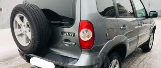
Today, a huge number of security systems are produced, designed for a variety of needs. The standard Lada Kalina alarm system, as a rule, is installed directly during vehicle assembly, which explains its name. I would like to draw attention to the not entirely pleasant aspects associated with the operation of the standard Kalina alarm, which consist in its inadequate operation. That is, the system can turn on at any time by itself. If you examine such problems in detail, it turns out that all of them are not causeless.
According to the principle of operation, the standard alarm system on a Lada Kalina car is practically no different from similar devices. The functions of the system also include actions such as locking and unlocking, which are carried out using a special remote control. The device is installed in a key fob on a bunch of keys. It is possible to lock the doors. This is done by turning the key in the driver's side door. In addition, locking and unlocking can be done from inside the cabin by pressing a special button. The alarm turns on when strangers try to break into the car.
As for the problem of false alarms, such malfunctions often occur when car owners try to install shock or vehicle tilt sensors on their car.
As practice shows, most often false alarms occur in cars painted in dark colors. Dark colors are known to attract heat. When the machine is left in an open place under the sun's rays for a long time, a large amount of thermal energy accumulates. The result may be surface deformation due to excessive heat, which triggers the shock sensor.
Original
| Name / article / OEM / front | Price, rub.) |
| ALNAS 2110-3501070 (diameter 24 cm) | from 1500 |
| ALNAS 2108-02 Euro (diameter 24 cm) | from 1600 |
| Autoreal 2110-3501070 (13 inches) 13r | from 1400 |
| Autoreal 2112-3501070 (14 inches) / 14r | —/— |
| 7701206339 (without ABS) 14r | —/— |
| 7701207795 (with ABS) Lada Kalina 2 | —/— |
| ALNAS 2112-03 Sport Lada Kalina 1117-1119 | from 2200 |
| ALNAS 2112-3501070 | from 1550 |
| ALNAS 2110-03 Euro | from 1700 |
| ALNAS 2110-02 Sport | from 2000 |
DIY security system installation
The installation of an alarm system in Kalina is carried out after removing the dashboard and disassembling the steering column to make it easier to install the wires.
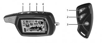
Keychain for standard Kalina alarm system
From the wires located under the dashboard you will need:
- 2 wires transmitting signals to the turn signals;
- wire directing the signal to the hood;
- similar wire for the trunk;
- wires for doors;
- two-phase wires (+/-);
- parking brake wire.
You will also need instructions describing all the steps, which must be studied very carefully. The operations are performed in the following order.
- You need to take the turn signal wires going to the dashboard. Connect 2 wires with blue and black-blue.
- Connect the parking brake wire, which is necessary for automatic engine starting, to the same harness. You should find a blue-brown wire and connect it to the handbrake.
- Next you need to check the operation of the motor. This can be done using a generator, that is, the appearance of voltage during ignition indicates a successful start. Then a connection is made with a brown-white wire, soldered and insulated.
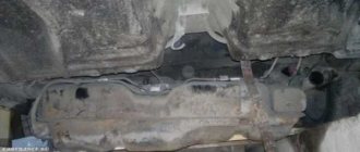
- We move down from the dashboard to the BUS, which lies under the seat at the back, on the left, closer to the bottom of the driver's door. Here you will need only 2 wires responsible for opening and closing the doors. We connect the “minus” of the system to any body bolt.
- connect to the pink-black wire responsible for unlocking the doors.
- We take the white-pink wire responsible for closing the door. You need to be especially careful because in poor lighting it can be confused with black and red, since they are similar. The black and white hood wire is also located here.
Return to contents
1. Car alarm connection points for VAZ 1118 Kalina 2005
ChainColorPolarityLocationTurn signals Blue and Blue/Blackpositive Driver's threshold or Steering column Door sensors (driver's door) Red/Blue negative Driver's threshold Door sensors (all) White/Blue At the ceiling lamp Central Z. lockingPink/WhiteDriver's thresholdC.Z. unlockingPink/BlackFuel pumpGreypositiveWorking with the glass unit control unit
Window control unit Kalina Sport
After reading the manual, you should start by connecting the hood and trunk wire ends. The color of these wires is the same - black and white. How can you tell them apart? The wire transmitting the signal to the trunk is always located on the right, the hood wire is located to the left. We connect to the luggage wire. To avoid making mistakes during installation, remember that the trunk wire is the outermost. Then you need to connect the limit switches from the door wires in such a way that the doors then close. To do this you will need 3 1 Ohm diode bulbs.
There is 1 limit switch coming from the doors, while in the BUS there are 3 such door limit switches: 2 for the front doors and 1 for both rear doors. Therefore, the alarm wire must be separated into 3 parts and soldered to each one with one short one. Then solder 1 diode there, and then connect it to the brown-red wire of the front door on the right, to the white-blue wire of the front left, and the white-red wire to the rear. The wiring diagram should be included in the manual.
At the next stage, we connect the LED to the left post, having previously made a hole. For reliability, we secure the part with something on the other side. The antenna must be attached approximately in the same place as the rear view mirror, at a distance of about 5 mm. The shock sensor can be installed on the metal under the mat. If we talk about installing it on plastic, this is not a very good idea, since it can lead to false alarms.
As for autorun, everything is not so complicated. The 1st wire is positive, the 2nd and 3rd are ignition, and the 4th is starter. When the IMMO is activated, you also need to purchase a keyless unit to bypass the standard immobilizer, connect it to the break point of the white wire, which is located near the wall of the stove heating or near the center console. Other wires that you will later need are located there.
Substitutes
| vendor code | Price, rub.) | vendor code | Price, rub.) |
| Lightweight brake drum made of cast iron Pilenga 6224 | from 1600 | Fenox TO2108O3 | from 1700 |
| LPR 7D0271 (diameter 200 mm, height 50 mm.) | from 1800 | TRW DB4307 | —/— |
| Brembo 14707910 | —/— | Bosch 0986477146 | —/— |
| ATE 24.0220-0020.1 | —/— | BREMBO 14.7079.10 | —/— |
| TRW DB4171 | —/— | TRW DB4187 | —/— |
Two configurations and two schemes
In the “Norma” version, if it has a central locking system, you can use two control wires. Ground is supplied to one of them if the locks need to be opened, and to the second one if the locks need to be closed. The period of connection to ground should take 0.7 seconds, and most alarms have such a setting.
If we talk about the “Lux” configuration, the control wires will not help us here. The relay contacts built into the alarm will have to be connected to the breaks in the power cords. Despite all the complexity, there were no complaints about this scheme, and we will consider it right now.
The “luxury” option is the most complex
First you need to make sure that the central locking system in the car is really connected according to the “Lux” scheme. The control button located on the door must be trigger (non-latching). If you have exactly this type of car, you will have to tinker. It will be necessary to extend 4 power cables to the signaling unit. These cords, in turn, must go from the break point of the two standard wires (yellow-white and yellow-black). Find them in the bundle under the threshold.
Any alarm system is supplied with two relays, one of which is activated for closing, the second for unlocking the locks. Power cables drawn from the break points are connected to the relay contacts.
The part of the yellow-white wire that goes to the actuators is connected to the common contact. Another relay contact (normally closed) is connected to the second half of the cable. They connect to the yellow-black wire in a similar way, but here an opening relay is used, not a locking one. Each of the normally open contacts receives power.
Any power wiring is supplied with power through a fuse.
In our case, the rating “15 Amperes” is used. Immediately before installation, you need to call the pair of wires that are directed to the actuators. The probe should show a value of 1.2 - 1.3 Ohms. And of course, when performing installation work, you first need to remove the negative terminal from the battery. Be careful!
Connection option for “Norma”
Let's say there is a switch in the driver's door, but it has two fixed positions. Then it will be easy to connect the alarm. You will need to make not 4, but 2 taps, and not from the power cords, but from two signal cords. There is no need to make breaks, just make a T-shaped connection. The diagram here looks standard:
You can complete the installation without breaking the wires at all.
In the circuit discussed above, there is no fuse. We connected to the signal wiring, not the power wiring, and theoretically we can not be afraid of any short circuits. Still, it is better to insulate the free terminals on the signaling. The same applies to all connection points.
Substitutes
| vendor code | Price, rub.) | vendor code | Price, rub.) |
| ABS 17342 | from 1300 | METELLI 23-0411 | from 1350 |
| BOSCH 0 986 479 346 | —/— | LPR L1052V | from 1400 |
| BREMBO 09.8903.14 | from 1500 | TRW DF4107 | —/— |
| FERODO DDF1147 | —/— | BREMBO 09.8903.75 | —/— |
| VAZ (R13) ventilated LUCAS DF4108 | —/— | TRW 2110-3501070 | —/— |
| 2110-3501070/71 | —/— | —/— |
Recommendations for both cases
First of all, we note that when connecting the relay to the power wiring, you cannot make the control pulse too long. Setting the value for more than a second can burn out the actuators. Here we were talking about programming, and now let's talk about the electrical part. As you know, before installation you need to open the hood and disconnect the negative terminal.
This advice should not be ignored in any case.
As for installation, it will be better if the power wire taps are carried out by an auto electrician. With signal wiring, everything is simpler, but the rules will be the same in each case:
- Do not let the cord touch the insulation to metal parts. If contact occurs, additional protection is used. For example, a heat-resistant tube placed over electrical tape is suitable;
- It is better to connect any power cables using twisting. Each twisting point is carefully isolated.
- The cross-section of wires carrying significant current must be sufficient so that the conductor does not heat up. This is how you can protect yourself from unforeseen consequences.
The last tip concerns power wiring. And the ability to twist is a whole art.
You cannot learn this art in one day.
When connecting any equipment, you should strive to make as few changes as possible to the standard wiring.
There must be an opportunity to do the following: return everything as it was. Sometimes it happens that one or more signaling parameters do not take a value that is suitable for the car. And then, the alarm system is changed or they refuse to use it altogether. This needs to be taken into account.