Any car will last you for the rest of your life if you drive hard enough
Injection power units on rear-wheel drive classics, a prominent example of which is the VAZ 2107-20, have had a serious impact on the domestic passenger car fleet. But not all car owners initially appreciated the advantages of the injection system in comparison with a traditional carburetor, fearing more difficulties in the operation of electronic components. Is this really so, we will try to figure it out within the framework of this article.
Representative of the rear-wheel drive VAZ family, which received an injection system
What's new
The main innovation was the replacement of the mechanical functions of the ignition system and preparation of the air-fuel mixture with electronic devices, which are more accurate and efficient. The wiring diagrams of the VAZ 2112 and the Samara family also underwent a similar modernization. Accordingly, the wiring of the VAZ 2107 to the injector received differences from the carburetor version.
Under the hood of the VAZ 2107-20, the absence of a carburetor and distributor is immediately striking
ECM functions
The electronic engine control system (abbr. ECM) took on the following operating parameters of the power unit:
- Controlling the amount of air and gasoline entering the car engine cylinders,
- crankshaft speed
- Spark plug control;
- Adjustment of ignition timing in all operating modes;
- Turning the electric fuel pump on and off,
- Control of the electric fan of the engine cooling system.
The photo below shows a VAZ 2107 wiring diagram for an injector with an M1.5.4N ECM and a January-5.1.3 controller
Injection system VAZ 2107
Electrical diagram
The classic 2107 wiring on cars with an injection system has also undergone changes. In particular, under-hood elements equipped with connectors for sensors and electronic devices have appeared.
Electrical diagram of VAZ 2107 with carburetor
For reference: The developers of Moskvich 2141 followed a similar path. True, they had a more global problem - the lack of their own engine.
Explanation for the electrical diagram of the carburetor VAZ 2107
For reference: The photo below shows the electrical wiring of a VAZ 2107 to an injector with catalog numbers. The differences from carburetor kits are in the engine compartment harnesses.
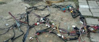
When converting the engine to an injection system, you should also purchase new wiring
Electrical circuits for VAZ 2107 cars with injection and carburetor engines
The electrical wiring of all versions of the VAZ 2107 is the same, with the exception of the engine compartment wires. The electrical network is built according to a single-wire circuit, the second conductor is the car body and the crankcases of the units. When using VAZ 2107 electrical circuits, you should take into account the likelihood of a restoration repair being carried out on a particular vehicle, since sections of the wiring may have been replaced.
Differences in work
Advantages
So, what are the benefits received by the car owner whose car has injection installed:
- There is less chance of stalling when starting from a standstill - the electronics react more flexibly to the operation of the gas pedal, allowing you to move off more confidently from idle;
The engine compartment wiring harness of the VAZ 2107-20 has different connectors
- Easy engine starting - there is no need to manually operate the choke knob;
- Reduced warm-up time for a cold engine - the electronic system optimizes the minimum stable speed. You can start moving after starting, without fear of jerks and dips typical of a carburetor;
- Reduce routine maintenance of electrical equipment . In particular, there is no need to constantly adjust the gap in the breaker contacts;
For reference: Other domestic car factories also modernized electrical equipment, in particular the ignition system - see the publication on the UAZ 31514 wiring diagram.
- Reduced adjustment work on the carburetor - electronics can reduce fuel consumption and make engine operation more environmentally friendly.
In the video you can see the stable start of the VAZ 2107 injection engine.
Flaws
The injection system also has some flaws, in particular:
- Without a diagnostic tool, it is quite difficult to identify a malfunction in the engine management system;
- Standard wiring 2107 does not allow troubleshooting using a warning lamp;
- The factory instructions most often instruct you to contact a service center for diagnostics. However, the price of such a service is not always justified for the car owner.
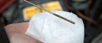
In the photo - diagnostics of the oxygen sensor of the VAZ 2107
Failure of the main vehicle systems
The reason for the sudden failure of many components of the VAZ 2107 car may be damage and failure of electrical wiring elements.
The most common wiring failures are listed below:
- A common defect is a blown fuse link caused by a circuit overload or short circuit. Since the electrical circuit of the VAZ 2107 often uses old-style fuses, oxidation or loosening of the contact clamps in the mounting block often occurs. To correct these faults, replace the fuse or clean the contacts. The latest car releases used mounting blocks with blade fuses, which provide better contact and more reliable operation of the electrical circuit.
- A more complex case is the burning or oxidation of conductive tracks in the mounting block. To repair, the unit is removed from the car, the damaged areas are soldered and covered with protective varnish. In case of critical damage, the unit must be replaced.
- When a section of the wiring is short-circuited, the fuse-link will constantly burn out. To find a damaged element, you need to test the circuit with a multimeter. Replaced wires should be carefully laid along the standard route. An open circuit is also determined by the continuity of the wires.
- If there is a problem with the components of the injection system, the Check Engine indicator light on the instrument cluster may turn on. The cause may be sensor failure or broken circuits. To find the causes of damage, you should diagnose the injection system using a test device connected to the diagnostic connector. The error codes available in the system can be deciphered and repairs are made based on this data.
- The cause of complete inoperability of the electrical system may be a discharged battery or oxidation of the negative wire that is connected to the body. A low battery is indicated by a dim glow of the control lamps and their complete shutdown when a load is connected (horn or an attempt to crank the engine with the starter).
- A burning battery charging lamp with the engine running indicates a malfunction of the generator or an open circuit connecting the generator to the battery.
- Light pulsations when the engine is running are a symptom of a burnt-out control relay on the generator. The relay must be replaced, since operating the vehicle with increased voltage in the on-board network is unacceptable.
The video provided by the Avtoelektrika HF channel shows the repair of the wiring of the reversing lights on a VAZ 2107.
Electrical diagram VAZ-2107 carburetor
Electrical diagram of VAZ 2107, 21074 produced in 1988-2001 with generator 37.3701
- block headlights
- side direction indicators
- accumulator battery
- starter relay
- carburetor electro-pneumatic valve
- carburetor microswitch
- generator 37.3701
- gearmotors for headlight cleaners *
- Fan motor switch sensor
- engine cooling fan motor
- sound signals
- distributor
- spark plug
- starter
- coolant temperature gauge sensor
- engine compartment lamp
- low oil pressure warning sensor
- low brake fluid level indicator sensor
- windshield wiper motor
- carburetor electro-pneumatic valve control unit
- ignition coil
- headlight washer pump motor *
- windshield washer pump motor
- mounting block
- windshield wiper relay
- hazard warning and direction indicator relay
- brake light switch
- reverse light switch
- ignition relay
- ignition switch
- three lever switch
- hazard switch
- socket for portable lamp**
- heater fan switch
- additional resistor for the electric motor of the heater (stove)
- rear window heating indicator lamp
- low brake fluid level warning lamp
- signaling unit
- heater fan electric motor
- glove compartment lamp
- light switches on the front door pillars
- switches for warning lights of open front doors ***
- front door open warning lights ***
- connection block
- cigarette lighter
- watch
- instrument light switch
- diode for checking the serviceability of the low brake fluid level indicator lamp
- fuel level indicator
- fuel reserve indicator lamp
- speedometer
- turn signal indicator lamp
- carburetor choke indicator lamp
- battery charge indicator lamp
- carburetor choke warning switch
- instrument cluster
- econometrician
- light switches on the rear door pillars
- coolant temperature gauge
- tachometer
- parking brake indicator lamp ("handbrake")
- low oil pressure warning lamp
- high beam indicator lamp
- indicator lamp for turning on external lighting
- voltmeter
- parking brake indicator switch ("handbrake")
- outdoor light switch
- rear window heating switch with backlight
- rear fog light switch with on/off indicator *
- fog light circuit fuse
- lampshade ****
- tail lights
- level indicator and fuel reserve sensor
- connectors for connecting to the rear window heating element *
- license plate lights 2107
Wiring diagram VAZ-2107 carburetor - full view:
Additional designations
When connecting a generator or tampering with the wiring and ignition system of a VAZ, you should know the location of the fuse box in the car. There are 17 of them in total, of which 2 are reserve.
- reverse gear rear lamps;
- electric motors for headlight and glass washer pumps;
- heated rear window;
- direction indicators, hazard warning lights;
- fog lights;
- tachometer, voltmeter, warning lights on the dashboard;
- cigarette lighter and clock;
- sound signal;
- interior lighting, brake lamps;
- high beam headlights;
- high beam warning lamp;
- engine compartment lighting and license plate lighting;
- glove compartment lighting;
- low beam on the right;
- low beam on the left.
The electrical diagram of the VAZ 2022 car will help in repair and maintenance. You can download the image in high resolution using the link.
Mounting block connection diagram
P1 — relay for turning on the heated rear window; P2 - relay for turning on the headlight cleaners and washer; P3 - relay for turning on sound signals; P4 - relay for switching on the electric motor of the engine cooling system fan; P5 - headlight high beam relay; P6 - low beam headlight relay; A - the order of conditional numbering of plugs in the mounting block blocks. The outer number with the letter “Ш” in the plug designation is the block number, and the inner number is the conventional number of the plug.
Conventional numbering of plugs in blocks
Additionally, to repair or tune a VAZ, you will need to know the serial numbers of the plugs in the blocks. The electrical diagram of the VAZ 21074 gives the following designations:
- Headlights, windshield and headlight wipers, power supply valve control unit, windshield wiper relay.
- Mounting block and three-lever switch.
- Signal and turn signals.
- Rear block lights.
- Alarm switch.
Schemes of individual blocks of the seven
Power supply system
Power plant starting system
1 - starter; 2 - relay; 3 — ignition switch; 4 - battery
Ignition system
1 - generator; 2 — ignition switch; 3 - distributor; 4 - breaker; 5 — candles; 6 - coil; 7 - battery
Contactless ignition system
External and internal lighting
Windshield wipers and washers
1 — electric motors of the windshield wiper; 2 — washer motor; 3 — mounting block; 4 — ignition switch; 5 - washer switch
Cooling Fan
1 — fan electric motor; 2 - sensor; 3 — mounting block; 4 - ignition relay; 5 - ignition switch.
VAZ 2107 on-board network systems and the principle of their operation
Considering that the “sevens” were produced with both carburetor and injection engines, their electrical circuits are different.
The electrical circuit in the carburetor VAZ 2107 is somewhat simpler than in the injection ones
The difference between them is that the latter have an on-board network supplemented with an electronic control unit, an electric fuel pump, injectors, and sensors for the engine control system.
The injection VAZ 2107 circuit includes an ECU, an electric fuel pump, injectors and control system sensors
Regardless of this, all electrical equipment of the “seven” can be divided into several systems:
- car energy supply;
- starting the power plant;
- ignition;
- external, internal lighting and light signaling;
- sound alarm;
- additional equipment;
- engine control (in injection versions).
Let's look at what these systems consist of and how they function.
Energy supply system
The VAZ 2107 energy supply system includes only three elements: a battery, a generator and a voltage regulator. The battery serves to provide electricity to the vehicle's on-board network when the engine is turned off, as well as to start the power plant by supplying power to the starter. The “sevens” use lead-acid starter batteries of type 6ST-55 with a voltage of 12 V and a capacity of 55 Ah. Their characteristics are quite sufficient to ensure the start of both carburetor and injection engines.
VAZ 2107 was equipped with 6ST-55 batteries
A car generator is designed to provide electric current to the vehicle's on-board network, as well as charge the battery when the power unit is running. Until 1988, “Sevens” were equipped with generators of the G-222 type. Later, VAZ 2107 began to be equipped with current sources of type 37.3701, which had successfully proven themselves on the VAZ 2108. Essentially, they have the same design, but differ in the characteristics of the windings.
The generator generates current to provide electricity to the vehicle's on-board network
Generator 37.3701 is a three-phase electromechanical alternating current device with electromagnetic excitation. Taking into account the fact that the on-board network of the “seven” is designed for direct current, a rectifier is built into the generator, which is based on a six-diode bridge.
The generator is installed on the power plant of the machine. It is driven by a V-belt from the crankshaft pulley. The amount of voltage generated by the device depends on the number of crankshaft revolutions. To ensure that it does not go beyond the limits established for the on-board network (11.0–14.7 V), a microelectronic voltage regulator of the Ya112V type works in tandem with the generator. This is a non-separable and non-regulated element that automatically and continuously smoothes out voltage surges and dips, maintaining it at a level of 13.6–14.7 V.
The basis of the power supply system is a battery, a generator and a voltage regulator
The generator begins to produce current when we turn the ignition key to position “II”. At this moment, the ignition relay is turned on, and voltage from the battery is supplied to the exciting winding of the rotor. In this case, an electromotive force is generated in the generator stator, inducing an alternating current. Passing through the rectifier, alternating current is converted to direct current. In this form, it goes to the voltage regulator, and from there to the on-board network.
Also check out the electrical diagram of the VAZ 21074: https://bumper.guru/klassicheskie-modeli-vaz/elektrooborudovanie/vaz-21074-inzhektor-shema-elektrooborudovaniya-neispravnosti.html
Video: how to find a generator malfunction
Power plant starting system
The VAZ 2107 engine starting system includes:
- battery;
- starter with relay;
- ignition switch (lock).
1 - starter; 2 - relay; 3 — ignition switch; 4 - battery
As a device for starting the power unit in the VAZ 2107, a four-brush DC electric starter of the ST-221 type is used. Its circuit does not have protection in the form of a fuse, but it provides two relays: an auxiliary (power supply) and a retractor, which ensures the coupling of the device shaft with the flywheel. The first relay (type 113.3747–10) is located on the engine panel of the machine. The solenoid relay is mounted directly on the starter housing.
The ST-221 starter is installed in the VAZ 2107
The engine start is controlled using the ignition switch located on the steering block. It has four positions, by moving the key to which we have the opportunity to turn on the circuits of various electrical equipment:
- “0” – a position in which all electrical devices are turned off, with the exception of the sound signal, cigarette lighter, interior lamp, and sometimes the radio (depending on how it is connected);
- “III” – exterior headlight lamps, windshield washer and wipers are powered;
- “I” – power is supplied to the ignition system, to the instrument panel, warning lamps and heater fan;
- “II” – current is supplied to the starter relay, retractor and starter field windings.
The engine starts as follows. When the key is turned to position “II,” the corresponding contacts of the ignition switch are closed, and current flows to the terminals of the auxiliary relay, starting the electromagnet. When its contacts also close, power is supplied to the windings of the retractor. At the same time, voltage goes to the starter. When the retractor relay is activated, the rotating shaft of the starting device engages with the flywheel crown and through it transmits torque to the crankshaft.
Using the lock, various circuits of the machine's on-board network are switched on
When we release the ignition key, it independently returns from position “II” to position “I”, and the current stops supplying the auxiliary relay. This opens the starter circuit and turns it off.
Video: if the starter does not turn
Ignition system
The ignition system is designed for timely ignition of the combustible mixture in the combustion chambers of the power plant. Until 1989 inclusive, the VAZ 2107 was equipped with a contact type ignition. Its design was:
- a coil representing a voltage-increasing transformer;
- distributor with contact breaker;
- high voltage wires;
- candles.
1 - generator; 2 — ignition switch; 3 - distributor; 4 - breaker; 5 — candles; 6 - coil; 7 - battery
The ignition coil is used to increase the voltage coming from the battery. The classic (contact) ignition system used a two-winding coil type B-117A, and the contactless one used 27.3705. Structurally they are no different. The difference between them lies only in the characteristics of the windings.
Video: repair of the ignition system of the VAZ 2107 (part 1)
The distributor is necessary to interrupt the current and distribute voltage pulses across the spark plugs. In the "sevens" distributors of type 30.3706 and 30.3706–01 were installed.
By means of high-voltage wires, high-voltage current is transmitted from the contacts of the distributor cap to the spark plugs. The main requirement for wires is the integrity of the conductor and insulation.
Spark plugs produce a spark at their electrodes. The quality and time of the fuel combustion process directly depends on its size and power. From the factory, VAZ 2107 engines were equipped with spark plugs of type A-17 DV, A-17 DVR or FE-65PR with an interelectrode gap of 0.7–0.8 mm.
The contact ignition system worked as follows. When the ignition was turned on, the voltage from the battery went to the coil, where it increased several thousand times and followed the contacts of the breaker located in the ignition distributor housing. Due to the rotation of the eccentric on the distributor shaft, the contacts closed and opened, creating voltage pulses. In this form, the current entered the distributor slider, which “carried” it across the contacts of the cover. These contacts were connected to the central electrodes of the spark plugs via high voltage wires. This is the path the voltage passed from the battery to the spark plugs.
After 1989, the “Seven” began to be equipped with a contactless ignition system. This was due to the fact that the breaker contacts constantly burned and became unusable after five to eight thousand kilometers. In addition, drivers often had to adjust the size of the gap between them, as it constantly got lost.
The contactless ignition system uses a switch instead of a breaker
The new ignition system no longer had any distributor. Instead, a Hall sensor and an electronic switch appeared in the circuit. The operating principle of the system has changed. The sensor read the number of revolutions of the crankshaft and transmitted an electronic signal to the commutator, which, in turn, generated a low voltage pulse and sent it to the coil. There, the voltage was increased and supplied to the distributor cap, and from there, according to the old scheme, it was supplied to the spark plugs.
Video: repair of the ignition system of the VAZ 2107 (part 2)
In the injection-powered "sevens" everything is much more modern. Here in the ignition system there are no mechanical components at all, and the role of the ignition coil is played by a special module. The operation of the module is controlled by an electronic unit, which receives information from several sensors and, based on it, generates an electrical impulse. Then it transmits it to the module, where the pulse voltage increases and is transmitted through high-voltage wires to the spark plugs.
In injection VAZ 2107, the electrical impulse is generated by the ECU
System of external, internal lighting and light signaling
The vehicle lighting and alarm system is designed to illuminate the interior of the cabin, the road surface in the front and rear of the car in the dark or in conditions of limited visibility, as well as warn other road users about the direction of the maneuver by giving light signals. The system design includes:
- front block headlights;
- turn signal indicators (side indicators);
- rear lights;
- salon lamp.
The lighting system includes front and rear headlights, turn signal indicators, and interior lamp
VAZ 2107 was equipped with two front block headlights, each of which combined high and low beam headlights, side lights and direction indicators in its design. Far and near lighting in them is provided by one double-filament halogen lamp type AG-60/55, the operation of which is controlled by a switch located on the steering column on the left. The turn signal unit contains a lamp of type A12–21. It turns on when you move the same switch up or down. The side light is provided by A12-4 type lamps. They light up when you press the exterior lighting switch. The turn signal also uses A12-4 lamps.
The rear lights of the “seven” are divided into four sections:
- direction indicator (lamp A12–21–3);
- side light (A12–4);
- fog light (A12–21–3);
- reversing lights (A12–21–3).
The rear fog lights light up when you press the button to turn them on, which is located on the center console of the car. The reversing headlights turn on automatically when you engage reverse gear. A special “frog” switch installed in the rear of the gearbox is responsible for their operation.
The interior of the car is illuminated using a special lamp located on the ceiling. Its lamp turns on when the side lights are turned on. In addition, its connection diagram includes door limit switches. Thus, the lamp starts to glow when the side lights are turned on and at least one of the doors is open.
The lampshade is designated number 64
Sound alarm system
The sound alarm system is designed to provide a sound signal to other road users. Its design is very simple, and consists of two electric sound signals (one high-pitched, the other low), relay R-3, fuse F-7 and a power button. The sound alarm system is constantly connected to the on-board network, so it works even when the key is pulled out of the ignition switch. It is turned on by pressing a button located on the steering wheel.
1 - high and low tone signals; 2 — mounting block; 3 - power button
The sound sources in the “sevens” are signals like 906.3747–30. Each of them has a trim screw to adjust the tone. The design of the signals is non-separable, therefore, if they fail, they must be replaced.
Video: repair of the VAZ 2107 sound signal
Additional electrical equipment for VAZ 2107
Additional electrical equipment of the “seven” include:
- electric motors of the windshield wiper gear motor;
- windshield washer pump electric motor;
- cigarette lighter;
- heater fan motor;
- radiator cooling fan electric motor;
- watch.
Windshield wiper motors drive a trapezoid, which in turn moves the windshield wipers across the car's windshield. They are installed in the rear of the engine compartment, immediately behind the engine shield of the car. The VAZ 2107 uses gearmotors of type 2103–3730000. Power is supplied to the circuit when the right steering column switch is moved.
The washer motor drives the washer pump, which supplies water to the washer line. In the "sevens" the motor is part of the design of the pump built into the tank lid. Part number 2121–5208009. The washer motor is activated by pressing the right steering wheel switch (towards you).
1 — electric motors of the windshield wiper; 2 — washer motor; 3 — mounting block; 4 — ignition switch; 5 - washer switch
The cigarette lighter, first of all, is not used to allow the driver to light a cigarette from it, but to connect external electrical equipment: a compressor, navigator, DVR, etc.
The cigarette lighter connection diagram consists of only two elements: the device itself and fuse F-6. Switching on is carried out by pressing the button located at the top of it.
The cigarette lighter is connected to the on-board network via a fuse without a relay
The heater fan electric motor is used to force air into the vehicle interior. It is installed inside the heating unit. The device catalog number is 2101–8101080. The electric motor can operate in two speed modes. The fan is turned on with a three-position button located on the dashboard.
The electric motor of the radiator cooling fan is used for forced air flow of the main heat exchanger of the vehicle when the coolant temperature exceeds the permissible values. Its connection diagrams for carburetor and injection “sevens” are different. In the first case, it is turned on by a signal from a sensor installed in the radiator. When the coolant is heated to a certain temperature, its contacts close and voltage begins to flow into the circuit. The circuit is protected by relay R-4 and fuse F-7.
1 — fan electric motor; 2 - sensor; 3 — mounting block; 4 - ignition relay; 5 - ignition switch
In the injection VAZ 2107, the scheme is different. Here the sensor is installed not in the radiator, but in the cooling system pipe. Moreover, it does not close the fan contacts, but simply transmits data on the refrigerant temperature to the electronic control unit. The ECU uses this data to calculate most commands related to engine operation, incl. and to turn on the radiator fan motor.
In injection "sevens" the electric radiator fan is turned on by a signal from the ECU
The clock is installed inside the car on the dashboard. Their role is to show the time correctly. They have an electromechanical design and are powered by the machine's on-board network.
The clock is constantly connected to the on-board network
Engine management system
Only injection power units are equipped with a control system. Its main tasks are collecting information about the operating modes of various systems, mechanisms and engine components, processing them, generating and sending appropriate commands to control devices. The system design includes an electronic unit, injectors and a number of sensors.
The ECU is a kind of computer in which a program is installed to control the operation of the engine. It has two types of memory: permanent and operational. The computer program and engine parameters are stored in permanent memory. The ECU controls the operation of the power unit, checking the serviceability of all components of the system. If a breakdown is detected, it switches the engine to emergency mode and gives a signal to the driver by turning on the “CHEK” lamp on the instrument panel. The RAM contains current data received from sensors.
The injectors are designed to supply gasoline to the intake manifold under pressure. They spray it and inject it into the receiver, where a flammable mixture is formed. At the heart of the design of each of the nozzles is an electromagnet that opens and closes the nozzle of the device. The operation of the electromagnet is controlled by the ECU. It sends electrical impulses at a specific frequency, causing the electromagnet to turn on and off.
The control system includes the following sensors:
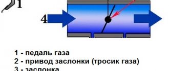
- Throttle position sensor. It determines the position of the damper relative to its axis. Structurally, the device is a variable resistor that changes resistance depending on the angle of rotation of the damper.
- Speed sensor. This element of the system is installed in the speedometer drive housing. A speedometer cable is connected to it, from which it receives information and transmits it to the electronic unit. The ECU calculates the speed of the car based on its impulses.
- Refrigerant temperature sensor. As already mentioned, this device serves to determine the degree of heating of the refrigerant that circulates in the cooling system.
- Crankshaft position sensor. It generates signals about the position of the shaft at a certain point in time. This data is necessary for the computer to synchronize its operation with the cycles of the power plant. The device is installed in the camshaft drive cover.
- Oxygen concentration sensor. Serves to determine the amount of oxygen in exhaust gases. Based on this information, the ECU calculates the proportions of fuel and air to form the optimal combustible mixture. It is installed in the intake area immediately behind the exhaust manifold.
- Mass air flow sensor. This device is designed to calculate the volume of air entering the intake manifold. The ECU also needs such data to correctly form the fuel-air mixture. The device is built into the air duct.
The operation of all systems and mechanisms is controlled by the ECU
Information sensors
The information sensors of the VAZ 2107 include an emergency oil pressure sensor and a fuel level indicator. These devices are not part of the engine management system, since the engine can work well without them.
The emergency oil pressure sensor is designed to determine the pressure in the lubrication system and promptly notify the driver when it drops to critical levels. It is installed in the engine cylinder block and connected to a warning lamp located on the instrument panel.
The fuel level sensor (FLS) is used to determine the volume of fuel in the tank, as well as warn the driver that it is running low. The sensor is installed in the gas tank itself. It is a variable resistor, the slider of which is attached to the float. The fuel level sensor is connected to a gauge located on the instrument panel and a warning lamp located there.
Sensors are connected to instruments and warning lamps
Wires for connecting electrical appliances
| Connection type | Section, mm 2 | Insulation color |
| Negative terminal of the battery - vehicle ground (body, engine) | 16 | Black |
| Starter positive terminal - battery | 16 | Red |
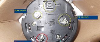
| Positive contact of the generator - plus battery | 6 | Black |
| Generator - black connector | 6 | Black |
| Terminal on the generator “30” – white MB block | 4 | Pink |
| Starter connector “50” – starter relay | 4 | Red |
| Starter Start Relay - Black Connector | 4 | Brown |
| Ignition switch relay - black connector | 4 | Blue |
| Ignition switch output “50” – blue connector | 4 | Red |
| Ignition switch connector “30” – green connector | 4 | Pink |
| Right headlight plug - ground | 2,5 | Black |
| Left headlight plug - blue connector | 2,5 | Green, gray |
| Generator output “15” – yellow connector | 2,5 | Orange |
| Right headlight connector - ground | 2,5 | Black |
| Left headlight connector - white connector | 2,5 | Green |
| Radiator fan - ground | 2,5 | Black |
| Radiator Fan - Red Connector | 2,5 | Blue |
| Ignition switch output “30/1” – ignition switch relay | 2,5 | Brown |
| Ignition switch contact “15” – single-pin connector | 2,5 | Blue |
| Right headlight - black connector | 2,5 | Grey |
| Ignition switch connector “INT” – black connector | 2,5 | Black |
| Six-pin block of the steering column switch - “ground” | 2,5 | Black |
| Two-pin block of the steering column switch - glove box illumination lamp | 1,5 | Black |
| Glove compartment light - cigarette lighter | 1,5 | Black |
| Cigarette lighter - blue block connector | 1,5 | Blue, red |
| Rear window defroster - white connector | 1,5 | Grey |
↑ The principle of operation of the VAZ 2106 and 2107 starter
The starter covers are secured to the housing with 2 bolts. Both covers (back and front) have bronze-graphite bushings that act as rotation bearings. In them, a starter armature rotates on a shaft, from which rotation is transmitted through a drive to a flywheel mounted on the crankshaft.
↑ Traction relay
When voltage is applied to the starter motor, the solenoid relay engages the gears of the drive reducer and the flywheel ring gear. By turning the car's ignition key to the "starter" position, voltage is applied to the pull-in and holding windings of the traction relay. When the contacts of the traction relay are closed, the power to the pull-in winding is turned off.
↑ Overrunning clutch
On the drive shaft there is a roller overrunning clutch connected to the drive gear, which transmits unidirectional rotation to the engine. After starting the engine, the clutch opens, which protects the starter from damage due to the increased speed of the rotating internal combustion engine.
Car wiring diagram
1 – radiator fan drive motor; 2 – relay and fuse block (mounting block); idle speed sensor; 4 – engine control unit; 5 – potentiometer; 6 – set of spark plugs; 7 – ignition control unit; 8 – electronic crankshaft sensor; 9 – electric fuel pump; 10 – tachometer 2107; 11 – lamp for monitoring the health of electronic systems; 12 – ignition system control relay; 13 – speed sensor; 14 – diagnostic connector; 15 – set of injectors; 16 – adsorber solenoid valve; 17, 18, 19 – fuse block protecting the injection system circuits; 21 – electronic fuel pump control relay; 22 – electronic relay for controlling the intake pipe heating system; 23 – intake pipe heating system; 24 – fuse protecting the heater circuit; 25 – electronic oxygen level sensor; 26 – cooling system temperature control sensor; 27 – electronic air damper sensor; 28 – air temperature sensor; 29 – pressure control sensor.
↑ Scheme for switching on direction indicators and hazard warning lights with a breaker relay
1 — block headlights with front direction indicators; 2 — side direction indicators; 3 — mounting block; 4 - ignition relay; 5 — ignition switch; 6 — relay-interrupter for direction indicators and hazard warning lights; 7 - turn signal indicator lamp located in the speedometer; 8 — rear lights with direction indicator lamps; 9 — alarm switch; 10 — direction indicator switch in a three-lever switch;
- A - to terminal “30” of the generator;
- B - numbering of plugs in the hazard warning switch;
- B - the order of conditional numbering of plugs in the relay-interrupter of direction indicators and hazard warning lights.
Relay-interrupter 6 is designed to receive an intermittent light signal from the direction indicators both in the emergency mode and in the turn indication mode, as well as to monitor the serviceability of the direction indicator lamps. If the lamps are working properly, then in the turn indication mode it causes warning lamp 7 to blink at the usual frequency. If the lamps are faulty (burnout or break in the lamp circuit), then the breaker relay ensures that the control lamp blinks twice as fast.
The breaker relay is mounted under the instrument panel on a bolt welded to the wall of the air supply box. A faulty breaker relay cannot be repaired and should be replaced with a new one.
The breaker relay must ensure blinking of the direction indicator lamps with a frequency of 90±30 cycles per minute at a rated load of 92 W, an ambient temperature of –20 to +50°C and a voltage of 10.8 to 15 V.
Until 1985, the 23.3747 relay-interrupter, assembled on integrated circuits, was used. It created a constant lighting of the control lamp in the event of any of the turn signal lamps burning out or an open circuit in its power supply.
Since 1985, a relay-interrupter 231.3747, made of discrete elements, has been installed.
The characteristics of both relay interrupters are the same. The only external difference is that relay-interrupter 231.3747 does not have plug “5”. The supply voltage is supplied only to plug “1”. Therefore, there is no need for the brown wire that previously connected plug “5” of the breaker relay with plug “6” of the alarm switch 9.
In 1995, the hazard warning switch was slightly modified. His terminals “5” and “6” were eliminated, as well as the connection diagram of the control light inside the switch was changed.
Fuse and relay diagram 2107
On newer “sevens” a block with 17 fuses and 6 relays is installed. VAZ 2107 fuses on the “new” unit protect the following electrical circuits and devices:
- Reversing lamps, heater fan, rear window defroster warning lamp and relay, rear wiper motor and rear washer pump.
- Electric motor for front wipers.
- Reserve socket.
- Reserve socket.
- Power supply for heated rear window.
- Clock, cigarette lighter, power socket “carrying”.
- Signal and radiator fan.
- Turn signal lamps in emergency mode.
- “Fog lights” and a relay that regulates the voltage of the on-board network.
- Instrument panel lamps.
- Brake light bulbs.
- Right high beam headlight.
- Left high beam headlight, high beam warning lamp.
- Side lights (rear right, front left), license plate and engine compartment lighting.
- Side lights (rear left, front right), glove compartment and cigarette lighter lamps.
- Low beam (right lamp).
- Low beam (left lamp).
The block relays perform the following functions:
- Heated rear window relay.
- Headlight cleaner and washer relay.
- Signal relay.
- Cooling system electric fan relay.
- High beam relay.
- Low beam relay.
The fuse block of the VAZ 2107 (injector) is no different from the block on the carburetor “seven”. Injection models are simply equipped with an additional relay and fuse box installed in the cabin under the glove compartment. The block includes three relays - the “main” relay, the fuel pump relay and the fan relay.
G222 generator connections
In this form, it goes to the voltage regulator, and from there to the on-board network. VAZ wiring diagram By carefully studying the diagram presented on the page, any questions regarding the maintenance of the electrical equipment of the seven will disappear. It is also necessary to monitor the tightness of the terminals. All elements of the electrical equipment of the VAZ are powered by a battery. The sensor is electromagnetic and is used in electronic injection systems. The operation of all systems is controlled by switches and relays, and electricity to devices most often comes through the ignition.
This was due to the fact that the breaker contacts constantly burned and became unusable after five to eight thousand kilometers. Generator system connection diagram For repairs, the car must be driven into an inspection pit or overpass. Figure 8-5. Left high beam headlight, high beam warning lamp.
Electrical diagram of the VAZ-2107 car
The hazard warning switch is located in the steering column housing. There are certain values established by the maintenance standards for VAZ vehicles, but no one will use torque tools in garage conditions. If a spark jumps when the engine is rotated by the starter, then the coil is working; Distributor and spark plug chains. Before carrying out the removal work, it is necessary to disconnect the negative terminal [...] November 03 The rear lights of the VAZ are a combined design that includes the taillights, rear brake light, turn signals, reversing lights and fog lights. All bundles are connected to each other using a mounting block located in the rear of the engine compartment.
It is enough for the generator drive belt to deviate from its original position by .5 cm under medium force. The safety block is located on the right side of the engine compartment between the engine compartment on the partition. The ammeter must have an upper measurement limit of 10 A or more direct current, as well as overload protection.
In the case when the arrow always shows a full tank, the malfunction of the device is checked by disconnecting the white block from the combination and applying 12 volts to it. Wiring diagram of a VAZ carburetor with a description Wiring diagram of a VAZ carburetor with a description is supplemented by an electronic control unit, an electric fuel pump, injectors, as well as sensors of the control system sufficient for starting and carburetor engines of a VAZ engine. In most cases, the factory layout of the car provides for the presence of a generator of the type: Conclusions As you can see, knowledge principles of operation of the classic and contactless system of a VAZ car will help you quickly determine the cause of the failure. How to find a short circuit in the wiring. Methodology of auto electrician Valery Chkalov.
Modifications of the VAZ-2107 car
VAZ-2107 . Basic version of the sedan, with an 8-valve carburetor VAZ-2103 engine, 1.5 liters.
VAZ-2107-20 . The same VAZ-2107, but with a 1.5-liter VAZ-2104 injection engine that meets the Euro-2 environmental standard.
VAZ-2107-71 . The car for the Chinese market was equipped with a VAZ-21034 engine, with a volume of 1.4 liters and a power of 66 horsepower, specially tuned for A-76 gasoline. The pistons were taken from a VAZ-2108.
VAZ-21070 . Modification of a car with an 8-valve, carburetor VAZ-2103 engine, volume 1.5 liters.
VAZ-21072 . Modification with an 8-valve carburetor VAZ-2105 engine, volume 1.3 liters.
VAZ-21073 . An export modification for the European market, which was equipped with a 1.7-liter injection engine with a capacity of 84 horsepower. The engine of this car had a catalytic converter that satisfied environmental protection requirements.
VAZ-21074 . Modification with an 8-valve, carburetor VAZ-2106 engine, volume 1.6 liters.
VAZ-21074-20 . Modification with a 1.6-liter VAZ-21067-10 injection engine, which complies with the Euro-2 environmental standard
VAZ-21074-30 . Like the previous model, but with a VAZ-21067-20 engine, which meets the Euro-3 environmental standard
VAZ-210740 . Modification produced in 2010, equipped with a VAZ-21067 injection engine with a catalyst. Engine capacity is 1.6 liters, power is 72.7 horsepower.
VAZ-21076 . Export modification with a VAZ-2103 carburetor engine.
VAZ-21077 . Export modification with right-hand drive for the UK market. The car was equipped with a VAZ-2105 carburetor engine with a volume of 1.3 liters.
VAZ-21078 . Another export modification for the UK, but with a 1.6-liter VAZ-2106 carburetor engine
VAZ-121079 . The modification, developed specifically for the needs of the Ministry of Internal Affairs and the KGB, was equipped with a powerful VAZ-413 rotary piston engine with a volume of 1.3 liters and a power of 140 horsepower.
VAZ-2107 ZNG . The car is equipped with an 8-valve, fuel-injected VAZ-21213 engine with a volume of 1.7 liters.
Models of Lada VAZ 2107
- VAZ-2107 is a small passenger car with a closed monocoque four-door sedan-type body. Carburetor engine with a displacement of 1.45 liters of the VAZ 2103-08 brand with toxicity standards R-83. The maximum speed of the car is 150 km/h. It had the “Standard” package and was produced for the domestic market.
- VAZ 2107-01 - was equipped with two types of carburetor engine: 2103-08 carburetor, 1.45 liters; 2103-07 carburetor, 1.45 l. On the 2103-07 engine, a valve cover made of antiphon was installed. It has a maximum speed of 150 km/h. It has the “Norma” package and was produced for the domestic and foreign markets.
- VAZ 2107-02 - differs from the head model VAZ-2107 by an engine with a displacement of 1.45 liters and a system with distributed gasoline injection. The controller of the following models 2104-1411020-00 (01, 02) was installed. Equipped with a VAZ 2104 engine. It has a maximum speed of 145 km/h. It has the same five-speed gearbox. Has the “Standard” package. Produced for the domestic and foreign markets.
- BA3-21073 - differs from the VAZ-2107 car in its engine with a displacement of 1.3 liters and a central fuel injection system.
- VAZ-21074 differs from the VAZ-2107 by an engine with a displacement of 1.6 liters. The passenger car was equipped with an engine of two models: 2106-13 - carburetor; 21067-10 - with distributed fuel injection. The injection engine was developed to meet Euro-2 toxicity standards.
Explanation of symbols
Knowledge of the definitions of the 2107 Lada electrical circuit will help you quickly locate the required wire, diagnose it, identify and fix the malfunction. Of course, when replacing the cabin filter or changing the oil, such information will not be useful, but in specialized matters, deciphering the symbols will significantly simplify the repair process.
- 1 – head lights VAZ 2017;
- 2 – side turn signals;
- 3 – battery;
- 4 – starter activation relay;
- 5 – carburetor electro-pneumatic valve;
- 6 – internal carburetor switch;
- 7 – generator system 37.3701;
- 8 – gearmotors for headlight cleaners*;
- 9 – fan motor activation sensor;
- 10 – electric motor of the engine cooling fan;
- 11 – sound signals;
- 12 – ignition distributor;
- 13 – spark plugs;
- 14 – starter;
- 15 — coolant temperature indicator sensor;
- 16 – engine compartment lighting;
- 17 – critical oil pressure indicator sensor;
- 18 – warning lamp for insufficient brake fluid level;
- 19 – windshield wiper electric motor;
- 20 – power system valve control unit;
- 21 – ignition coil;
- 22 – electric motor of the headlight washer pump*;
- 23 – electric motor of the windshield washer pump;
- 24 – mounting block;
- 25 – windshield wiper relay;
- 26 – hazard warning and direction indicator relay;
- 27 – brake light switch;
- 28 – reverse lamp switch;
- 29 – ignition relay;
- 30 – ignition switch;
- 31 – three-lever switch;
- 32 – alarm switch;
- 33 – plug socket for a portable lamp**;
- 34 – heater heater fan switch;
- 35 – additional switch for the heater electric motor;
- 36 – indicator lamp for turning on the heated rear window;
- 37 – indicator lamp for insufficient brake fluid level VAZ;
- 38 – signaling unit;
- 39 – electric motor of the stove fan;
- 40 – glove compartment lighting lamp;
- 41 – lamp switches on the front door pillars;
- 42 – switches for warning lights of open front doors***;
- 43 – alarm lights for open front doors***;
- 44 – connecting block;
- 45 – cigarette lighter;
- 46 – hours;
- 47 – instrument lighting switch;
- 48 – diode for checking the serviceability of the warning lamp for insufficient oil pressure and brake fluid level;
- 49 – fuel level indicator;
- 50 – indicator lamp for insufficient gasoline level (fuel reserve);
- 51 – speedometer;
- 52 – control lamp for turning on the direction indicators on the dashboard;
- 53 – warning lamp for the carburetor air damper opening;
- 54 – indicator lamp for battery charge indicator;
- 55 – switch for signaling that the carburetor air damper is slightly open;
- 56 – instrument cluster;
- 57 – econometrician;
- 58 – lamp switches on the rear door pillars;
- 59 – coolant temperature indicator;
- 60 – tachometer;
- 61 – handbrake indicator lamp;
- 62 – low oil pressure indicator sensor;
- 63 – indicator lamp for high beam headlights;
- 64 – signaling device for turning on dimensions;
- 65 – voltmeter;
- 66 – parking brake warning switch;
- 67 – external lighting switch;
- 68 – rear window heating switch;
- 69 – rear fog light switch with on indicator*;
- 70 – fog light circuit fuse;
- 71 – interior lighting lamp****;
- 72 – rear lights;
- 73 – fuel level indicator and fuel reserve sensor;
- 74 – pads for connecting to the rear window heating element*;
- 75 – license plate lights.
↑ Starter device for VAZ-2106 and VAZ-2107
Starter VAZ-2106 device
1 — cover (drive side); 2 – retaining ring; 3 – restrictive ring; 4 – drive gear; 5 – roller overrunning clutch; 6 – drive ring; 7 – rubber plug; 8 – drive lever; 9 – relay anchor; 10 – holding winding of the traction relay; 11 – pull-in winding of the traction relay; 12 – relay tightening bolt; 13 – contact plate; 14 – relay cover; 15 – contact bolts; 16 – collector; 17 – brush; 18 – bushing on the armature shaft; 19 – cover (collector side); 20 – casing; 21 – shunt coil of the stator winding; 22 – body; 23 – stator pole fixing screw; 24 – anchor; 25 – armature winding; 26 – intermediate ring.