03/03/2022 2,018 Alarms
Author: Victor
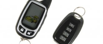
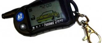
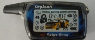
The KGB TFX 5 alarm system is a Russian-made anti-theft system model with two-way communication. This allows the car owner to always monitor the condition of the car when it is within the range of the key fob.
[Hide]
Specifications
The KGB TFKh car alarm with remote engine start has the following properties:
- transmission of commands between the security device and the communicator is carried out at a frequency of 433.92 MHz;
- the largest radius of operation of the key fob in command transmission mode is about 600 meters;
- the range of the communicator in message receiving mode varies around 1.2 km in ideal conditions (in the absence of interference);
- to power the security system, an electrical network is used, the voltage of which should be 12 volts;
- when the protection mode is turned on, the anti-theft installation will require no more than 25 mA of current;
- the number of security zones that the car protects is 6;
- the car owner can program up to four communicators into the memory of the microprocessor module;
- the system can operate correctly and execute commands in the temperature range from -40 to +85 degrees;
- For the communicator to function without failures, the ambient temperature must be from 0 to +40 degrees Celsius;
- The operating temperature for the siren varies from -30 to +85 degrees.
The range of operation of the key fob depends on the type of terrain, the absence of interference and the correct setting. At critically low temperatures, the device may malfunction. Also, extreme cold will affect the sensitivity of the shock sensor.
How to configure the KGB TFX 5 signaling and how to connect it
The presence of two engine locks and a built-in immobilizer function reliably prevents the theft of your car. Using the TURBO mode of the security system significantly increases engine life.
I've been scratching my brain for a long time! In the end, I simply forgot to plug the immo antenna into the crawler and the machine started working. :)) We dismantled the door trim. and crashed into a broken wire.
The hardest part about installing non-standard equipment is understanding how to install it. ? Most of the time is spent studying the instructions, diagrams and facts pouring out on the car.
This alarm system was on the car for about a year, after which it was replaced with another from a different manufacturer. In principle, this alarm will help you be aware of what is happening with your car and is sold at an affordable price...
Equipment
This alarm system for cars with automatic start and warning system has the following delivery set:
- main microprocessor module designed to control the installation;
- main communicator with three buttons on the body and a screen with two-way communication option;
- a spare pager, also equipped with three keys, but without a screen, so there is no feedback;
- an antenna module in which a temperature sensor and a call button for the car owner are installed;
- two-level shock sensor with cable and connector for connection;
- siren;
- LED lamp designed to determine the status of the anti-theft installation;
- button for activating the Valet service function with a conductor for connecting to the microprocessor module;
- button to enable anti-robbery mode;
- limit switch equipped with a terminal;
- mounting kit of wires for connecting the system with a block;
- cables necessary to connect the engine starting module automatically;
- block designed for connecting electric drive devices of locks;
- power supplies for installation in the main and spare panels;
- double-sided tape or sticker for attaching the antenna module and diode lamp to the windshield;
- service manual for the security system, which will allow you to install, connect and program basic functions;
- warranty card.
The package includes only one limit switch; other devices for the doors and luggage compartment must be purchased separately.
Security system delivery set
Is it possible to improve
Let's see what a car alarm looks like in analysis:
FX-5 PCB
The main element here is the PIC16F77 chip. It contains a processor, memory, and ROM with firmware. You cannot download the firmware on the Internet, and you cannot even read it by installing the chip in the programmer.
The FX-5 ver 2 kit is now available in retail. It differs from the “first version” in the firmware. But the only way to update is by replacing the chip.
The KGB alarm of the model in question is a copy of another security system. It is produced under the Starline brand and designated as Twage A8. It is also equipped with auto start, and the A8 and FX-5 key fobs are interchangeable. The bottom line is that you can buy a Starline controller with A8 firmware if you wish.
There is no support site for KGB security systems yet. And you will have to look for the basic manual, which you can download, on the seller’s website. More often they post a scan of a book available in the new version kits (ver 2). We wish you success.
Main functions
The KGB TFKh 5 system is characterized by expanded functionality. All signaling options can be divided into two classes - protective and service.
Protective
Overview of main functions:
- activation of light and sound alarms when the controllers are turned on in protective mode;
- sending notification pulses about the activation of the alarm function to a communicator equipped with a screen;
- remote activation of the Panic function, which will allow you to turn on the siren and lighting devices upon command from the remote control;
- power unit blocker mode;
- Anti-robbery function, which is activated by command from the communicator;
- Anti-robbery mode, activated using a special key;
- the possibility of blocking the car engine with its further preservation in the event of removal of the anti-theft system.
Service
Additional signaling options:
- silent protection of the power unit;
- activation of the car security option when the engine is running;
- silent activation and deactivation of the protection function;
- activation of security mode without a remote control;
- the ability to re-enable protection automatically in case of accidental shutdown;
- passive activation of the security function;
- the presence of an option to delay the activation of protection until the interior lighting turns off;
- independent check of all elements of the security complex when turning on or deactivating the protective mode;
- remote shutdown or activation of the sensitivity controller in protection mode;
- remote control of central locking;
- possibility of controlling central locking from the ignition switch;
- two-stage opening of door locks;
- two-pulse door unlocking;
- the possibility of additional connection of electric sunroof closers and window regulators, which will allow these elements to be closed automatically when the security system is turned on;
- emergency mode Valet for controlling the protection system and some options without a remote control;
- emergency deactivation of the protective function using a personal password;
- the presence of four additional channels for controlling additional vehicle equipment;
- control of the lighting system in the car interior;
- vehicle search function in the parking lot;
- option to remotely configure new communicators and delete information about old remote controls from the memory of the microprocessor module;
- resetting the operating parameters of the anti-theft system to factory values;
- function of calling the car owner from the passenger compartment;
- determining the temperature inside the car;
- the communicator display displays information about the current time, alarm clock data, and timer information;
- the presence of a battery discharge monitoring system installed in the main remote control.
The “Live video blog” channel spoke in detail about the capabilities of the anti-theft system, as well as the service functions of the KGB TFH 5.
Alarm system KGB TFX 5 programming key fob buttons
Dmitry Glukhikh showed what problem a consumer may encounter when setting up the remote start option for an internal combustion engine.
It is necessary to lock all door locks, the hood and activate the protective mode. To do this, press the first button on the pager.
Remote engine starting is implemented in many KGB alarm models, namely:
- GX-5RS;
- FX-10;
- FX-8;
- FX-7;
- FX-5.
To activate the security mode of the KGB car alarm, press key I of the key fob once (key I is programmed to control the state of the security mode), one short beep and a single flash of the side lights will confirm the vehicle’s transition to security mode. Your car alarm should track the position of the key. One cable from the “power” connector is connected in any case. This is a yellow insulated cord. Do not skip connecting it, otherwise you will not be able to complete the setup.
You can set up a convenient ignition control routine in automatic and manual mode. When it is turned on, the locks of the device may, firstly, not lock, and secondly, be configured to operate after a certain period of time (10 or 30 seconds). If the engine starting system is turned off, the locking of the locks is automatically released.
The KGB TFX 5 car alarm instructions, which come with each kit, will help you install the system yourself.
We started by pulling out the unnecessary wiring from the alarm blocks so that they would not interfere. Next we cut the loop. Well, the disassembly of the interior began: Removing the left deflector, the instrument panel, the lower part of the dashboard on the driver’s side, the lower ECU covers, the visor with the mirror and the “cover” of the left glass pillar, and the steering wheel cover.
You can also perform a “reset”. The amendments will be as follows: in step 1 you need not 6, but 10 clicks, and in step 3 select “option 1”. Then press “key 1” on the key fob, as when selecting “value 1”. The settings are reset to “factory values”.
How to install correctly?
Installation of the KGB TFX 5 alarm system can be done independently. To install, you must carefully study the service documentation and connection diagrams.
Safety regulations
Basic requirements for installing an alarm system:
- Before performing the task, you need to turn off all electronic devices and equipment, the ignition system and turn off the power to the on-board network. To do this, the battery is disconnected from the power supply in the engine compartment.
- The security system is installed on vehicles with a 12-volt power supply. The negative output of the car alarm is always connected to the negative terminal of the battery.
- Before performing the task, it is recommended to test all wires using a test connection. You must ensure that the cables are intact and that the connections are correct. It is first recommended to assemble the entire circuit and connect it to the battery to make sure the system is working.
- If the car is new and still under warranty, you must contact an official representative of the car manufacturer before installation. On relatively new vehicles, tampering with standard electronics is not allowed, as is drilling holes in the body.
- The microprocessor unit must not be installed under the hood of a vehicle or near sources of moisture. Overheating and condensation will cause damage to the device. The module must not be installed in places with strong vibration.
- All fixing elements for fastening modules and blocks are used only those included in the package. The use of non-standard parts may lead to incorrect operation of the alarm.
Recommendations for placement and installation
Tips for installation and location of parts:
- The microprocessor device is installed in an inaccessible place under the interior trim. This could be the space behind the car radio, glove compartment, or under the dashboard. It is important that the driver and unauthorized persons do not have direct access to the device. During installation, the unit must be properly fixed to prevent it from breaking when exposed to vibrations. You can additionally wrap the device with foam rubber.
- The antenna adapter is installed on the inner surface of the windshield, which must first be cleaned and degreased. The device must be placed higher to ensure high-quality signal transmission, and also away from metal products.
- Installation of the Valet service button is carried out in the car interior. The driver must have access to the button when he is in his seat, but it must be hidden. It is recommended to place the element under the control panel and disguise it by wrapping it with electrical tape.
- The siren is installed under the hood. It must not be installed next to the cylinder block. During installation, it must be taken into account that the device and its wires should not be accessible from under the bottom of the car. The siren horn should be placed down or to the side to prevent moisture from accumulating inside.
- The shock sensor is installed in the passenger compartment, in its central part.
- A limit switch is installed on the hood. These devices must also be placed on the doors and luggage compartment.
- The LED indicator is located next to the antenna module or in the windshield area.
Connection diagram of the main unit of the system
When connecting the microprocessor module, mistakes must not be made. This may lead to incorrect operation of the anti-theft system as a whole.
Map for connecting the microprocessor to other devices
Connecting a 6-pin connector
More information about connecting this block:
- Cables in black and white and black and yellow insulation are used to control activation and blocking of the starter mechanism during autostart. The user must cut the wire that comes from output 50/1 on the ignition switch. This cable should have 12 volts when the key is in the Start position. Both contacts must be connected to the cut part.
- The blue output is used as the ACC circuit enable output. It must be connected to a contact connected to the switch and supplying power to additional electrical equipment. This section of the circuit should have 12 volts when the key is in the ACC and ON positions.
- The red insulated cable is a high current 12 volt power input contact. It is designed to supply current to all wires that are powered by the built-in relays of the internal combustion engine starting system. It must be connected to the positive terminal of the battery and the circuit must be protected with a 30 amp fuse.
- The yellow wire is the activation output of the main ignition circuit. It must be connected to the standard ignition system cable, where there is 12-volt power when the key is in the ON position. If the key is in the OFF or ACC position, there should be no voltage on this section of the circuit.
- The wire in green insulation is a programmable output for activating the second electrical circuit of the ignition system or ACC. The standard cable option is to duplicate the yellow contact. If necessary, the car owner can configure this output to ACC mode.
Connecting an 18-pin connector
Features of connecting the 18-pin block:
- The red element is the plus of the 12-volt power supply. It must be connected to the positive terminal of the battery.
- The black cable is the negative of the electrical circuit and must be connected to the vehicle body. The wire contact must be of high quality.
- The cable in black and green insulation is designed for connecting to the light source of marker optics or turn indicators.
- The green/yellow wire is also used to connect to the side headlight or turn signal bulbs.
- The gray contact is the positive output for connecting to the siren. The maximum permissible load is 2 amperes.
- The black and blue output is used for connection with pushbutton switches on doors.
- The wire in gray-orange insulation is intended for connection with the hood limit switch.
- The white-orange cable must also be connected to the “limit switch” only installed on the tailgate.
- The black and yellow wire is the negative output of the additional first channel. The control signal time interval is one second. To connect, you will need an additional relay.
- The contact in the red-yellow shell is the negative output of the additional second channel. The maximum permissible load current is 300 mA. You can connect this contact to low beam optics.
- The blue-yellow insulated wire is the negative output of the additional third channel. It can be configured for two-stage opening of door locks or to control other components of the machine.
- The blue wire is the negative contact of the additional fourth channel. To connect it, you will need an additional relay. It is possible to configure a channel for connection to the interior lighting system or the power window control unit.
- The wire in yellow-black insulation is the negative output of the anti-theft system. It can be used to activate the protective function, turbo timer, Anti-Theft mode, and engine blocking.
- The white-black wire is the negative output of the security system status. Used to connect an external power unit locking relay.
The Mos-olimp channel talked about installing the KGB TFKh5 system and connecting all connectors using the example of a Toyota Highlander car.
Connecting electric lock drives
If the car is not standardly equipped with electric drives, you can install and connect them yourself:
- contacts in black-blue and black-green insulation are connected to the grounding, that is, to the car body;
- a red-black cable is connected to the 12-volt power supply;
- The blue contact is connected to the blue output of the electric drive opening system;
- The green contact element must be connected to the green closing wire of the electric actuator.
Safety precautions
Some nuances when using the alarm system.
- The system can be installed on cars with a 12-volt power supply.
- If it is necessary to drill the machine body for installation, it is best to clarify this point with the dealer. Otherwise, you may lose your warranty.
- Before installation, a test connection is made with all elements activated. This is necessary to identify a possible defect.
- The system must be secured only with the fasteners that are included in the kit. The use of third party parts may result in incorrect operation.
- Avoid getting water and detergents on the system elements; to do this, installation must be done in places inaccessible to moisture.
- If any alarm unit fails, there is no need to try to open it and carry out independent repairs.
- Do not use solvents or strong detergents to remove dirt from the surface of the device. It is best to do this with a dry paper napkin.
It starts by pressing button 1 of the key fob for about 2-3 seconds, until a melodic signal appears. If the car has a manual transmission, then you will first need to carry out a logical neutral, without this procedure there will be no autostart.
User manual
In accordance with the instructions for use, before starting setup, the user must make sure that the working batteries in the key fob are used. You need to remove the back cover of the remote control and install working batteries into it.
Setting up key fobs
To effectively use all functions, the remote control must be linked to the alarm control unit. Otherwise, the system may not work correctly.
Meaning of buttons and indicators
Description of key functions:
- The first button is used to program a command, as well as remote Start and Stop of the motor. To implement the last function, you need to hold it down for three seconds.
- The second key is used to assign a command that corresponds to the current position of the cursor on the communicator screen. Pressing this button for three seconds will open the tailgate.
- Simultaneously clicking on the first and second keys will activate the search function. If you hold down these buttons for three seconds, this will enable Panic mode with alarms and lights working.
- A short click on the third button will allow you to control the position of the cursor on the communicator screen, as well as turn off alerts. If you hold down the key for 3 seconds, this will allow you to set the clock, timer, alarm and power saving mode. When you press the button for 6 seconds. The key fob will go to the first key programming menu.
- When you press the first and third buttons simultaneously, the remote control will go to the notification mode selection menu.
- Clicking on keys 3 and 2 will allow you to quickly set the communicator's timer.
Description of the indicators on the display of the main communicator:
- Icon for determining the status of the power source in the remote control.
- Second additional channel.
- Function of automatic start of the internal combustion engine based on air temperature.
- The power unit of the car is started.
- Tailgate open indicator.
- Vibration alert function for the car owner.
- Indicator of open door locks in the doors.
- Activation of emergency mode Valet.
- Automatic re-enablement of protection mode.
- Silent security option.
- Indicator of activated protection mode with sound.
- Open car hood symbol.
- Indicator for determining impacts on the car body.
- Disengaged parking brake symbol.
- Closing door locks.
- Opening door locks.
- The communicator receiver is in active mode.
- Confirmation of communication with the vehicle.
- Driver call indicator.
- The power saving feature of your device is activated.
- Activation of the ignition system.
- Alarm option enabled.
- Determination of time - first half of the day.
- Afternoon.
- Function of daily start of the power unit.
- Indication of air temperature and time.
- Temperature indicator scale.
- Countdown timer.
- A - function of anti-robbery mode enabled or disabled.
- B—an additional third signaling channel is enabled or disabled.
- C - automatic start function of the power unit based on air temperature.
- D — daily autorun mode.
- E - remote start of the power unit is started or disabled.
- F—silent protection mode is enabled or disabled.
- G - car protection function with sound.
- N — remote switching off of the sensitivity controller.
- I — emergency mode Valet is enabled or disabled.
- J - determination of vehicle condition and temperature level.
- K - additional second channel is enabled or disabled.
- L - remote opening of the tailgate.
Designation of indicators on the key fob display
Key fob programming
To configure the keys, perform the following steps:
- On the communicator, click the third key two or more times to move the cursor on the device display. To change the direction of movement, a short pause is made.
- The third button moves the cursor to the position that corresponds to the required command.
- To program, press the same button; it must be pressed for six seconds. The key is held down until the communicator emits first a double and then a triple beep.
- To activate the selected option, press the first button on the key fob. The function corresponding to this key will also be assigned. If you need to assign an option to a second button, then after selecting the function you need to click on it.
Recording codes
Linking communicators is done as follows:
- The key is inserted into the lock to activate the ignition system.
- The button to enter the Valet service mode is pressed. It must be held until the alarm emits four beeps.
- To bind the main communicator, press keys 1 and 2 on the communicator simultaneously. If a spare pager is being programmed, then you must press elements 3 and 4. If the actions are correct, the siren should emit a sound signal.
- The rest of the communicators are also programmed.
- After completing the task, you need to turn off the ignition by removing the key from the lock.
The Sigmax69 channel talked about linking new communicators to the KGB TFKh 5 alarm system.
Enabling modes
The user can independently configure the operation of the modes:
- energy saving;
- alerts;
- security
Energy saving
To enable this feature, perform the following steps:
- The third button on the communicator is pressed. It must be held until the communicator plays a double melodic signal.
- Using the same key, the cursor on the screen must be moved to the position of the icon, made in the form of a battery. Next to the indicator there is the inscription Save.
- To enable the option, press the first key of the communicator. To disable this mode, you need to click on the second button.
- To exit the programming menu, the third key is pressed and held until the key fob plays a melodic signal.
Alerts
The main communicator can work with two modes of alerting the car owner - sound or vibration.
To select the signal type, you need to simultaneously click on the first and third buttons. If the vibration mode is activated, the vibration will work twice and the Mute icon will appear on the screen. When the sound warning system is activated, the Mute symbol will disappear from the display.
Security
Turning on the security mode when the power unit is running:
- With the engine running, pull the parking brake lever.
- On the communicator, click the first key and hold it until the car lights blink three times. The communicator should beep and an exhaust gas icon will appear on its display. The alarm status LED will remain on continuously.
- The ignition in the car is turned off, the key is pulled out of the switch. If the settings are performed correctly, the engine will remain in working condition.
- Within 30 seconds, the driver leaves the car, locks all the locks and the hood, and clicks the first button on the key fob. If the protection turns on, the turn lights will blink once and the siren will sound. The communicator should beep and display an icon of a closed lock, exhaust fumes, and a horn. In this protection mode, the shock and ignition sensors are turned off.
If the key fob is broken or non-functional, then to turn on the protection in an emergency, perform the following steps:
- The ignition turns on, but the engine does not start.
- Press the key to enter the service mode; click on it 8 times.
- The ignition in the car turns off. The siren will sound once, and the turning lights should also flash.
- Within 20 seconds, the driver leaves the car and locks all the door locks with the key. The siren will sound once, and the communicator will also play a sound signal. The protection will turn on.
To turn off the alarm in emergency mode, do the following:
- The door locks are opened with a key. This will trigger the car siren and play alarm signals.
- The ignition system is turned on, but the engine does not start.
- Within 20 seconds, the emergency Valet button is pressed four times.
- The car's ignition turns off. The turning lights should flash twice and the alarm siren will sound. Protection mode will be disabled.
The Sigmax69 channel talked about the emergency shutdown of the KGB TFKh 5 anti-theft system.
Engine starting
When configuring this option, the following requirements must be taken into account:
- the car must be parked in a ventilated area;
- before setting the mode, the parking brake lever is raised;
- in cars with a manual transmission, the selector must be set to neutral speed position, and in cars with automatic transmission - in parking mode;
- Before starting the internal combustion engine, you need to make sure that the power unit is in good working order and that all consumables are available.
Auto
To set up the daily start of the internal combustion engine in automatic mode, the cursor on the key fob display is moved to the Start indicator position. Then the second button on the remote control is pressed. The siren will sound and the vehicle's side lights will blink once. The key fob will play a melodic signal.
Remote
This feature can be configured in two ways:
- Place the cursor on the communicator screen in the position of the indicator labeled Start. Then the second pager button is clicked.
- Click on the first key of the communicator and hold it for three seconds. The alarm status LED will remain lit continuously. If the power unit starts, the car’s side lights will blink three times and the key fob will emit a melodic signal.
Programming basic functions and operating parameters
Options Setting Table
The setup procedure is as follows:
- The car's ignition turns on.
- The service key is clicked six times.
- The ignition is turned off. The LED light will blink six times, and the siren will sound the same number of times.
- The emergency mode entry button is clicked a certain number of times, which corresponds to the number of the selected option. With each subsequent click, the LED indicator will blink.
- Within ten seconds, you must click on the first and second keys, depending on the desired state of the option. The siren and communicator will play the appropriate number of signals.
- To move to the next option, click the emergency button, after which the required value is selected by pressing the communicator keys. These steps are repeated for all options that need to be changed.
- To exit the setup menu, turn on the ignition and wait until the system automatically exits programming mode. The vehicle's side lights should blink five times.
Setting up the system from scratch
Having opened the instructions for the KGB signaling, you can immediately find the table:
Customizable Features
The settings responsible for autostart alternate with security options, but there is nothing wrong with that. You can download the photo and print it on a printer - no changes were made during copying. Don't forget to connect the Valet module as well as "cord 5" of the power connector. You will also need the KGB TFX key fob.
Programming order
To access the settings, follow a set of steps:
- Turn on the ignition, press the Valet button 6 times, then turn off the ignition;
- There should be 6 beeps and 6 LED flashes;
- By pressing the Valet button, select the option number;
- By pressing a key on the key fob, a new value is set;
- Steps "3" and "4" can be repeated;
- Finally, the ignition is turned on.
You can also perform a “reset”. The amendments will be as follows: in step 1 you need not 6, but 10 clicks, and in step 3 select “option 1”. Then press “key 1” on the key fob, as when selecting “value 1”. The settings are reset to “factory values”.
System control panels
The TFX 5 key fob has a AA battery. Carry out all replacement actions near the alarm itself. Having removed the “old” element, press key 1 briefly. Then a “new” battery is installed.
Idle training
If the control cord was connected to the tachometer, function 8 is assigned a value of 3 or 4. But this will not be enough. Training required:
- Basic information set out in the instructions for the KGB TFX 5 alarm system
- First, turn on the ignition, press the Valet button 9 times and turn off the ignition;
- There should be 9 beeps;
- The ignition is turned on, the engine is started, and wait until constant speed is established;
- Press and hold the Valet button until a beep sounds or the LED goes out.
As a result, the alarm will recognize engine speed.
It is better to control the engine using the tachometer signal. You can install two parts into the wire gap: a capacitor with a capacity of 1 mKF (47 Volts) and a resistor of 400-600 kOhm.
Capacitors MBM 0.5 mKF
Advantages and disadvantages
The advantages that users note in their reviews?
- Affordable price for many consumers. This alarm model is the best option for the ratio of cost and quality.
- High volume of signals produced by the siren.
- Great functionality of the anti-theft complex. At an affordable price, the system has many features and options.
- Stable operation of the automatic engine start option. This function works correctly regardless of weather conditions and air temperature. The method for launching the option does not matter.
- The alarm package includes a detailed service manual for installation and connection of the system.
Disadvantages characteristic of this model:
- Weak protection of the vehicle body. This disadvantage is usually associated with incorrect settings of the sensitivity and shock sensor. With such a problem, the alarm may not respond to the removal of the windshield wiper blades and windshields.
- Consumers note that the key fob is not working properly. The package may include a defective device that will not function correctly.
- If the sensor sensitivity is set too high, this will lead to false alarms.
Video “Problems with autorun”
User Dmitry Glukhikh in his video showed a malfunction that can occur in the automatic start of an internal combustion engine.
Do you have any questions? Specialists and readers of the AUTODVIG website will help you ask a question
Was this article helpful?
Thank you for your opinion!
The article was useful. Please share the information with your friends.
Yes (50.00%)
No (50.00%)
X
Please write what is wrong and leave recommendations on the article
Cancel reply
Rate this article: ( 2 votes, average: 4.50 out of 5)
Discuss the article: