To check, you will need a multimeter, a car battery and a lamp with soldered wires, wires for connecting between the generator and the battery, and you can also take a drill with a suitable head, since you may have to twist the rotor by the nut on the pulley.
Alternator This causes significant current to flow through the valves and damages them.
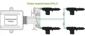
But, if for some reason there is no new one or there is no money to purchase it, and your hands grow where necessary, then you can install an external voltage regulator, for example a regulator Replacing a VAZ 2101 generator with a VAZ 2109 generator (Excitation connection diagram)
To repair the bearing assembly of this generator, you can attract specialists with less qualifications.
Let's see what the Russian market offers us to replace a failed generator, and at the same time test the proposed models in our testing laboratory.
I initially assumed that the startvolt was larger, but in fact it turned out to be almost more compact: Before installing the generator, I leveled the seats with a file and degreased them: After that, you can tighten them: The tightened terminals - both plus and minus are covered with a magic elixir: Instead of a bolt for adjusting the belt tension I also screwed in the pan pin.
If such symptoms occur, the separator elements, raceways, and slip rings should be checked for rotation. I know how to solder and love it, but I hope that I won’t have to: The rectifier plates are quite thick: The aluminum casting of the housing is of excellent quality, the generator is pleasant to hold in your hands: From a different angle: The front cooling impeller: The “pill” terminals of the relay-regulator are connected to the brush assembly soldering: The “tablet” itself does not have any markings.
Assessing the reviews of motorists, we can say with confidence: this generator is a variant of the classic reliable design without pretensions to outstanding performance, but guaranteeing trouble-free operation. Rectifier block.
Generator Startvolt LG 0101 for VAZ 2101 100A - yellow penny - Part 2
Dismantling and checking voltage regulators on a VAZ 2107
First, let's decide on the tools and devices that will be needed for the job. Here they are:
- household multimeter;
- open-end wrench 10;
- flat screwdriver;
- Phillips screwdriver.
Sequence of work
If the driver suspects that the voltage regulator is broken, then the first thing he should do is check the voltage supplied by the battery.
- The car engine turns off and the hood opens. Using a multimeter, the voltage between the battery terminals is measured. If it drops below 13 volts (or, conversely, rises above 14 volts), then this indicates a breakdown of the regulator.
- Having made sure that the battery is not charging well precisely because of a faulty regulator, it must be disconnected from the car's network, but first the ground wire must be removed from the battery. If this wire is not disconnected, then there is a high probability of a short circuit, which will lead not only to the burnout of many fuses in the closed section, but also to melting of the electrical wiring itself.
- If an old external regulator is installed on a VAZ 2107, then all terminals are manually removed from it, after which the nuts that hold the regulator to the car body are unscrewed with a 10-mm open-end wrench.
- If the VAZ 2107 is equipped with an internal three-level regulator, then to remove it you will need to unscrew a pair of mounting bolts holding this device in the generator housing with a Phillips screwdriver.
- After removing the regulator, the negative pole of the battery is connected to the relay ground (if the regulator is external), or to contact “Ш” (if the regulator is internal);
- The positive pole of the battery is connected to contact “K” (this contact is available on all types of regulators);
- The multimeter is connected either to the generator brushes or to the relay outputs.
- After turning on the multimeter and applying a voltage of 12–15 volts, it should also appear on the generator brushes (or on the relay outputs, if the regulator is external). If the voltage generated on the brushes or outputs remains constant, then this is a clear sign of a breakdown of the regulator. If no voltage is detected at the brushes or outputs at all, there is a break in the regulator.
- Both in the event of a breakdown and in the event of a break, the regulator will have to be changed, since this device cannot be repaired.
- The failed regulator is replaced with a new one, after which the vehicle's electrical system is reassembled.
Video: checking the voltage regulator on a VAZ 2107
Like any other device, the voltage regulator can break down suddenly. And it’s especially difficult for the driver if the breakdown occurs far from home. There is nothing surprising here: drivers who constantly carry spare regulators with them need to look further. But even in such a difficult situation, there is still a way to get home (or to the nearest service center). But you won’t be able to get there quickly, because every hour you’ll have to crawl under the hood and remove the terminals from the voltage regulator. And then, using a suitable piece of insulated wire, connect the positive terminal of the battery and contact “Ш” on the regulator. This is done so that the charging current does not exceed 25 amperes. After this, the regulator terminals return to their place, and the car starts. You can drive it for about 30 minutes, and you should turn on the maximum number of energy consumers - from the headlights to the radio. And after 30 minutes you should stop again and do the entire above procedure again, since without this the battery will simply recharge and boil.
So, even a novice car enthusiast can check the voltage regulator on a VAZ 2107. All that is required is the ability to use a multimeter and a screwdriver. Following the recommendations listed above will allow the car owner to save about 500 rubles. This is how much it costs at a car service center to check and replace the voltage regulator.
Checking a faulty generator
Let's consider the main malfunctions typical of automobile generator sets:
- Open circuit, short circuit and other damage. To diagnose such a malfunction, you need to check the number of amperes, as well as the voltage level at the output of the device. In accordance with the data obtained, a solution to this problem is selected.
- Often our compatriots are faced with such a problem as wear of graphite brushes, voltage regulator, and diode bridge. All worn out and failed elements can be repaired, but usually they are replaced. Separately, it should be said about the regulator - as mentioned above, it ensures optimal battery charge in accordance with the temperature in the engine compartment. Thus, the device automatically detects the number of volts for the battery under current conditions. Depending on the model of the generating set, a regulator with manual switching may be used in accordance with the time of year; in this case, sub-zero temperatures will not be harmful to the device. A broken relay can be indicated by unstable voltage in the system - for example, dim headlights that become brighter when you press the gas pedal.
- Bearing failure. Failure of these elements can be indicated by increased noise, but the same sign also indicates insufficient lubrication.
- Shui and howl. If such symptoms occur, the separator elements, raceways, and slip rings should be checked for rotation. Also, such a symptom may indicate a possible interturn short circuit in the windings of the stator mechanism or traction relay. In principle, when third-party sounds appear, you should also diagnose the state of the contacts.
- The temperature of a working generator set can be up to 90 degrees, but if there is obvious overheating, the diode bridge should be diagnosed. You also need to make sure that there are not many additional devices and devices connected to the vehicle’s on-board network. When the temperature rises critically, the insulation winding of the stator mechanism will first darken; moreover, it may melt.
- Worn generator set belt. If the alternator belt wears out and breaks, this will lead to incorrect operation of the unit as a whole, that is, all energy consumers in the car will be powered by the battery. If the belt breaks, the generator stops functioning, so the driver only has time to get to the nearest service station or garage to fix the problem. Voltage surges in the vehicle’s on-board network can indicate wear and tear. It is necessary to check the integrity of the strap and pay attention to its condition - cracks and other types of damage to the strap are not allowed. If they are present, then you need to understand that the belt will have to be changed soon.
Photo gallery “Main generator malfunctions”
Failure of the unit can also be indicated by too little battery charge or lack of voltage at its terminals. Also a sign of a device malfunction is the incorrect functioning of the display and equipment.
How does it all work?
First you need to understand how everything works. So, on the VAZ-2107, the on-board network is powered from two sources - the battery and the generator. The first provides electricity to all consumers until the power plant is started. The battery itself is a storehouse of electrical charge, which it releases when needed.
A generator is a unit that generates electricity, but for this it is necessary that it perform a mechanical action (its rotor rotates). In order for the generator to operate and power the network, it is driven from the crankshaft via a belt drive.
Everything works simply: to start the engine, the battery energy is supplied to the power electric motor - the starter, as well as the ignition system. After the power plant starts, the generator will be driven by the drive, the generated energy of which will power all devices. It will also be supplied to the battery to restore the charge spent on starting the power plant.
Recharging the battery from the generator must be carried out without fail, otherwise after several starts of the power plant, the loss of electricity in the battery will be significant (the battery runs out), and it will simply not be able to start the engine.
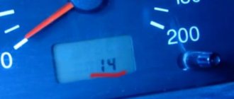
In order to monitor charging, a warning lamp and a voltmeter are installed on the dashboard of the VAZ-2107. Thanks to these control devices, it is possible to detect that the battery is not charging.
If the entire circuit through which the battery is recharged is in good condition, then after turning on the ignition, the charge indicator lamp lights up, but after starting the engine and entering the operating mode, it should go out, which indicates that voltage is supplied to the battery. In this case, the arrow on the voltmeter should be in the green zone, indicating that the voltage parameters correspond to the norm. But if, after starting the engine, the lamp lights up and “blinks”, while the arrow may twitch, this indicates a malfunction.
It should be immediately noted here that it often happens that the battery icon is on when the engine is running, but the voltmeter shows that charging is in progress. In general, the behavior of this system can be very different - charging is not happening, it is, but control devices show the opposite, recharging periodically disappears, but then is restored. In this case, there is a possibility of undercharging or overcharging, which are detrimental to the battery. A weak battery will eventually lead to it being completely discharged over time and making it impossible to start the car.
Cars before 1986
The G-222 generator was used in cars. The connection diagram for the VAZ-2107 is almost the same as on later models. But there are features, among the main ones - there is a control lamp indicating battery charging. Moreover, it worked using an electromagnetic relay.
When the ignition is turned on, power is supplied from the lock through the instrument panel fuse to the electromagnetic relay of the battery charge lamp and the coil contact. The second contact of the coil is connected to the center wire on the generator (the point where the three windings connect).
The electromagnetic relay has normally closed contacts, so when the ignition is turned on, the lamp lights up. But as soon as the engine starts running, the generator produces current. And a current flows through the control lamp coil, which causes the armature to attract and open the contacts.
At the same time, the power to the incandescent lamp stops and it goes out. This indicates that the battery is charging normally. Only when the power supply to the lamp stops will voltage be applied to the excitation winding and the generator will be able to return to operating mode.
Gas generator connection single and three-phase
The connection diagram for a three-phase power generator to a house or dacha in the presence of the same network implies similar connections as with a single-phase system. The only peculiarity: it is necessary to make more connections, since in this case the number of wiring strands is increased.
There is an important nuance: if you use a starter, then its contacts are intended for power wires, they will not be enough for the coil, you need to decide where to get the power for it.
Connecting a single-phase generator to the same network does not have the described complexity - there is only one phase, such a question simply does not arise. With three phases - L1, L2 and L3 - everything is more complicated. The solution is briefly simple: for the control circuit it is permissible to take any of the phases, but only one. For example, if the KM1 coil is powered from L3, then the control for the remaining starters, the start/stop keys, is also “hung” only on it. This is easy to do: mark with a marker or remember the color of the wire with the desired phase
We will consider phase mismatch briefly, since this is a separate topic. Connecting a three-phase gas generator to a single-phase network is possible, for example, using one of the power cores and a working zero. But the power is reduced by 3 times, and gasoline is consumed as usual. And if you separate 3 single-phase connections, phase imbalance may occur. Therefore, more complex schemes are used.
Connecting a single-phase generator to a three-phase home network is also possible. There are many schemes, but the simplest is this: parallel combination of 3 phases and connection to 1 phase of the power plant. At each phase the load will be distributed evenly.
Selection guide: you definitely need to buy a three-phase generator if the house has one and three-phase consumers at the same time, which often happens in private housing. Usually the product has a 380 V and a 220 V socket, that is, it can simultaneously power two types of devices.
Grounding
It is necessary to ground the backup source - a static charge arises on the case. It will be necessary to construct a separate grounding loop. It is ideal if it is possible to create a full-fledged structure, but a simple method is also suitable. You will need a metal rod 1.5–2 m, a bolt or clamp (metal), soft copper wire (large cross-section from 4 mm²). The core is connected with a clamp to the pin. Or they weld a bolt and attach it to it. The rod is driven into the ground, the other end of the wire is fixed to the generator housing.
So, the presented diagrams will help the user decide whether it is worth assembling autostart systems, buying an automatic transfer system, or getting by with manual start.
Now how to connect if the generator does not match the wiring?
You need to connect the generator without additional. diodes, and the wiring is three wires (with a light bulb)
If the old generator had additional diodes and used three wires for connection, but the new generator is simpler with a voltage regulator Y112A, and two wires are enough for it. In this case, the third wire from the light bulb simply remains unconnected. In this case, the light bulb stops working, but all machines of this generation have either a voltmeter or an ammeter and you can use them to control charging.
You need to connect a generator with an additional diodes, and the wiring is two wires
If the old generator was simple, without additional diodes and it needed two wires to connect, but the new, more modern one, with additional ones. diodes and requires three wires to connect, then you need to ignore the additional ones. diodes, forget about them and connect the generator as if it were without additional. diodes. But you will have to open the regulator housing and replace the voltage regulator, instead of Y112V put Y112A
If we leave the voltage regulator YA112V, then we need a separate wiring to connect the power output of the generator to a free point D.
When the ignition is turned on, a plus appears at point B, the regulator opens and a current from the generator plus appears in the excitation winding through the additional bus. diodes, and through brushes.
If the ignition is not turned on, then the current from the power output of the generator will not flow through the excitation winding to ground, because while there is no plus at point B of the regulator, the regulator transistor is closed.
This option is good because there is no need to change the regulator, it is very easy to connect the wiring, and because only a very small regulator switch-on current passes through the ignition switch, and the excitation current passes along a short path, from the generator output, through the additional bus. diodes, then to point B, to the brushes and through the transistor to ground. The disadvantage is the same as in circuits with Ya112A - if the engine is not running and the ignition is on, the battery is discharged through the field winding.
Features of connecting generators to a UAZ if the wiring does not match the generator
On UAZ cars with an old instrument panel, generators 6631(51).3701-01 are installed. This is a generator without extras. diodes, two wires go to such a generator.
On UAZ cars with a new instrument panel, they install generators 6631(51).3701 with additional. diodes, three wires go to such a generator.
Electrical diagram VAZ-2107 carburetor
Electrical diagram of VAZ 2107, 21074 produced in 1988-2001 with generator 37.3701
- block headlights
- side direction indicators
- accumulator battery
- starter relay
- carburetor electro-pneumatic valve
- carburetor microswitch
- generator 37.3701
- gearmotors for headlight cleaners *
- Fan motor switch sensor
- engine cooling fan motor
- sound signals
- distributor
- spark plug
- starter
- coolant temperature gauge sensor
- engine compartment lamp
- low oil pressure warning sensor
- low brake fluid level indicator sensor
- windshield wiper motor
- carburetor electro-pneumatic valve control unit
- ignition coil
- headlight washer pump motor *
- windshield washer pump motor
- mounting block
- windshield wiper relay
- hazard warning and direction indicator relay
- brake light switch
- reverse light switch
- ignition relay
- ignition switch
- three lever switch
- hazard switch
- socket for portable lamp**
- heater fan switch
- additional resistor for the electric motor of the heater (stove)
- rear window heating indicator lamp
- low brake fluid level warning lamp
- signaling unit
- heater fan electric motor
- glove compartment lamp
- light switches on the front door pillars
- switches for warning lights of open front doors ***
- front door open warning lights ***
- connection block
- cigarette lighter
- watch
- instrument light switch
- diode for checking the serviceability of the low brake fluid level indicator lamp
- fuel level indicator
- fuel reserve indicator lamp
- speedometer
- turn signal indicator lamp
- carburetor choke indicator lamp
- battery charge indicator lamp
- carburetor choke warning switch
- instrument cluster
- econometrician
- light switches on the rear door pillars
- coolant temperature gauge
- tachometer
- parking brake indicator lamp ("handbrake")
- low oil pressure warning lamp
- high beam indicator lamp
- indicator lamp for turning on external lighting
- voltmeter
- parking brake indicator switch ("handbrake")
- outdoor light switch
- rear window heating switch with backlight
- rear fog light switch with on/off indicator *
- fog light circuit fuse
- lampshade ****
- tail lights
- level indicator and fuel reserve sensor
- connectors for connecting to the rear window heating element *
- license plate lights 2107
Wiring diagram VAZ-2107 carburetor - full view:
Carburetor engines
The connection diagram for the VAZ-2107 generator (carburetor and injector) depends on the year of manufacture of the car. The first carburetor models had a G-222 generator installed. The same device can be found on commercially produced VAZ-2105 and VAZ-2104 models with a carburetor injection system.
The maximum output current for such an installation is 55 amperes. But in recent years, cars with fuel injection systems have become widespread. Its use implies a large current consumption, so it is necessary to use a generator with a high current to ensure a normal charge level and power supply to all consumers.
Design and principle of operation
As you know, the main purpose of a generator device is to convert mechanical energy into electrical energy. Thanks to this, the unit restores the capacity of the battery and also allows you to power all electrical equipment in the car. The generator device is located in the front of the power unit and is driven by the crankshaft.
More details about the main elements and principle of operation:
- Rotary mechanism. This element is a shaft with an installed field winding. Both halves of a given winding are located in opposite pole halves of the assembly. The rotor mechanism is driven by a belt drive.
- Slip rings are used to power the winding.
- Stator mechanism - consists of a winding and a core. This element is designed to generate alternating current. The current generated by the mechanism is fed through the rings further along the electrical circuit.
- In order for the generated excitation current to successfully reach the rings, brushes are used. These elements, as practice shows, often fail due to wear and tear.
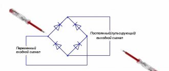
- Rectifier block. This component is designed to convert AC voltage. Structurally, this device consists of plates with installed diode elements. Depending on the pinout of the unit, the connection diagram for a car generator device may include a separate pair of winding diodes. In this case, voltage will not be able to pass through the battery when the engine is turned off.
- Regulator relay. This element is designed to maintain a certain voltage level in the on-board network within normal limits. The regulator relay directly affects the frequency as well as the duration of the current signals. The regulator itself structurally includes controllers, as well as executive components. Their purpose is to determine the time during which the winding must be connected to the network. If the regulator relay for some reason fails, stabilization of the incoming voltage to the battery is lost.
- The body of the device in which the main parts and components of the unit are located. The body itself is usually made of aluminum, so its weight is relatively light. The installation housing allows heat to be quickly dissipated, as a result of which the temperature does not reach a critical level. Also, the case is non-magnetic (the author of the video about the operating principle of the device is Mikhail Nesterov).
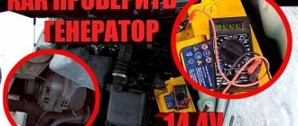
Ways to troubleshoot battery problems
First of all, you need to check the battery charging while the engine is running. During normal charging, the voltage will be in the range of 13.6 - 14.2 Volts. If the charge is weak, the value will be below 12 Volts (the author of the video is VAZ 2101-2107 repair and maintenance).
To troubleshoot problems, you need to prepare instructions with a diagram of the electrical equipment of the VAZ 2110 car and the necessary tools:
- pliers;
- flat and Phillips screwdrivers;
- multimeter;
- 12 V indicator light;
- knife;
- sandpaper.