Next we will look at how to correctly connect the signaling system on cars of the VAZ 2114 family. The following will be implemented: connection to the central locking, auto start, reading the status of door limit switches. To control the central locking, the VAZ plant produced BUBD modules. If such a module is missing, the task will be simplified - you will not connect the central locking system. The same applies to the case when the driver's door only has a switch, but not an actuator. All tables given here are suitable for the Starline A91 Dialog alarm system, and to set up another system, use the instructions for it.
Settings
Only autorun functions can be configured. To activate programming mode:
- Disable security
- The ignition key is set to position 0.
- Then press the Valet key six times in the main block.
- Turn on the ignition
- After six beeps, use the same key to select the desired function, and use the key to
- key fob select the desired value.
The optimal settings for VAZ - 2115.2114 will be the following: function 12 - set to value 3, function 11 - value 4, function 9 - value 3. To select value 4, press and hold the third button until the melody is played. After playing, press it again.
To check the correct connections, perform the following steps:
- Disconnect the yellow cord from block A91 to terminal 15 for a while.
- The engine is started using the ignition key
At the same time, the alarm indicator should blink.
Didn't find the information you are looking for? on our forum.
We recommend reading:
Is it possible to fill Priora with 98 gasoline, manufacturer’s recommendations
How to install the clutch release on a VAZ 2109, step-by-step description of removing the clutch with video
Gasoline consumption per 100 km VAZ 2107, average figures for a working car
Replacing the VAZ 2110 voltage regulator without removing the generator
Exhaust for VAZ 2110 8 valves
Installing the ignition button on a VAZ
How to remove the window regulator on a VAZ 2114, step-by-step description with photos
Rating of rear brake pads for vases
Checking the correct connection
Having installed all the elements of the alarm system, they configure the functions after activating the registration mode. To do this, you need to turn off the ignition, press the Valet button six times, and turn on the ignition. The sound of the signal six times will confirm the system’s transition to registration mode.
The selection of functions is made by pressing the buttons on the alarm key fob. The correct connection is checked by performing the following operations:
- Disconnect the wire (yellow) going from the A91 alarm control unit to the ignition switch to the terminal with the blue wire.
- The ignition key is used to start the engine
- The intermittent light of the alarm indicator confirms that the system elements are connected correctly.
In order to increase the level of protection of your car, you won’t need a lot of material costs. But only on the condition that the installation of the alarm system is done independently, with your own hands.
- How to connect an alarm system with auto start yourself
- Starline A91 characteristics
- Fuse for radio VAZ 2114
- What kind of oil to fill in VAZ 2114
How to connect
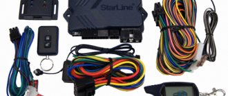
Installation of the VAZ-2114 alarm system begins with disconnecting the battery and determining the location of the elements. The control unit is placed under the instrument panel or behind the glove box, the siren is placed in the engine compartment. Guided by the instructions and diagram, all elements are connected.
The control unit is connected through connectors to system elements, components and vehicle parts. Installation and installation begin from the farthest point of installation of the security system element, using 9 connectors (X) for connection.
Sensors (limit switches) are installed in the engine compartment, under the hood and in the trunk, which react to opening. The door trims are dismantled to install activators. The Valet service button is installed in a place hidden from prying eyes, but easily accessible to the car owner.
A transmit-receive antenna is installed on the windshield in the upper corner. It is recommended to install the shock sensor inside the passenger compartment, securing it to a metal surface. The emergency siren is installed in the engine compartment with the bell facing down.
When all the elements are located in their places, you can begin to connect them into a single system.
Scheme
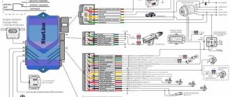
The characteristics of the Starline A 91 car alarm and the connection diagram of the main elements are given in the manufacturer's instructions. When connecting a 6-pin connector X 2, you may need an additional door opener activator.
When connecting door opening sensors, use the blue/red wire of connector X 3. All alarm connection points, i.e. connectors (X) look like this:
- X 9 - connect a two-level shock sensor installed on a metal surface.
- X 8 and X 7 - connectors are not used.
- X 6 - Valet service button, installed in a hidden and easily accessible place.
- X 5 - LED indicator, installed on the instrument panel.
- X 4 - transmitting sensor receiving module; it is recommended to install it in one of the upper corners of the windshield.
- X 3 - connector with many wires.
They are connected to the systems with wires of the following colors:
- Red - with the “plus” of the ignition switch.
- Green/yellow and green/black - sidelights and side turns.
- Black—vehicle mass.
- Yellow - ignition switch (connection to blue/black).
- Gray is the “plus” of the emergency siren.
- Blue/red - “plus” of the door entrance.
- Black/red - additional blocking relay.
- Orange/gray - hood lift sensor.
- Orange/white - trunk opening sensor.
- Orange/purple - to the brakes (according to the diagram in the instructions).
- X 2 - connect door opening activators;
- X 1 - ignition switch (closed with red wire).
Connecting the central lock
In basic configurations, the control unit (CU) of the central locking (CL) performs the function of locking the door lock. The electrical circuit connection diagram is the same for all central locks, the only difference may be in the control unit, activators and the number of pins for connecting an additional device.
The main elements of the central lock include the control unit, door sensor switches (limit switches) and microswitches that fix the position of the key. All these elements are connected to the alarm and interior lighting of the car.
To connect to the central locking, it is necessary to connect the central locking control unit (CU) to the car alarm using the door opening and closing relay, to the car ignition switch and to the door opening sensors. When installing the central locking, you will need additional parts, such as:
- diode 1A - 3 pcs.;
- 3A diode - 1 pc.;
- diode 5A - 2 pcs.
Tapping into wires
In order to insert into the wires, you first need to free them from under the threshold trim. To do this, unscrew the fastening screws and remove the upholstery. Underneath there are 2 wire harnesses running to the instrument panel. One of the harnesses contains the parking brake wire. 2 wires are connected to the sidelights and side indicators.
When inserting into the parking brake wire, 1 diode is installed, and 2 diodes are installed in the wire that powers the side headlights and side turn indicators. The terminals of the insertion wires are connected to connector X 3 of the alarm control unit.
Autostart
One of the functions of the Starlin car alarm system is auto engine start. In order to install with autostart yourself, you need to use the ignition switch wires. The lilac wire is connected to the battery. Blue (ignition switch) is connected to the alarm control unit via connector X 1.
To connect the tachometer sensor, it is connected to a gray/black wire coming from connector X 3. Connect ground from the main unit using the black wire of connector X 3.
How to make autostart with your own hands? Do-it-yourself autostart module and circuit
The VAZ-2114 models use an ignition switch with three terminals - 15 (blue wire), 30 (lilac) and 50 (red). Terminal 30 is connected to the battery. When you turn the key, blue wire 15 is connected to this terminal. The third terminal is responsible for the starter.
As it is written in the instructions, it is quite possible to power the alarm from contact 30, from which the lead is made. And the cable from connector X1, yellow, is connected to connector 15.
This will allow the alarm to control the speed. And at the very end we connect the ground from the main unit. This is a black cord from connector X3.
Lada 2114 in stock › Logbook › Installation of an alarm system with auto start Tomahawk Z5 on 2114
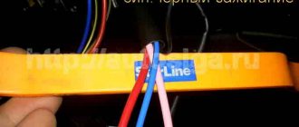
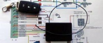
Good day, dear readers! Today I will tell you about the successful experience of installing an alarm system with auto start Tomahawk Z5 on my VAZ 2114 car. The previous alarm system installed in the car (Superbarricado SQ7500a) was more advanced, but due to some features of connecting to the electrical wiring, namely the presence of a data transmission interface in it CAN bus, made it a practically useless opener - a shouter without autostart, without blocking the starter and engine. This alarm was given to me by a neighbor as not working, the electricians at the auto repair shop were unable to “fix” it, and it later turned out that the battery in the key fob was dead and all I had to do was “push” it for it to start charging again. Dismantling the old alarm system turned out to be much easier than installing a new one (do not break it, don’t build it), and after 10 minutes all the wires were disconnected. It was also not difficult to determine which wire came from where, there were only four wires left - two for the central locks, more precisely for the electric drives of the locks, and two for the hood and trunk switches. The new alarm system has a lot more wires, so it took almost 4 hours to install it. First of all, the front panel of the dashboard was disassembled, I don’t think it’s worth explaining how this is done, this has already been written about many times and you can easily find instructions in the Internet. To simplify connections to the vehicle's electrical wiring, guillotine-type clamps (Scotch lock) were purchased.
In order not to cut the power wires to the starter, and not to solder to the power wires of the ignition switch, it was decided to make an adapter that is inserted into the plug and connector between the ignition switch and the car wiring.
The price of all adapters and clamps is around 200 rubles on the radio market.
The central alarm unit was secured behind the instrument panel with two self-tapping screws to the air duct.
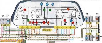
Gray-black alarm wire
the engine control input was connected to the tachometer input, pin 2 of the white block of the instrument panel, brown with a red stripe
.
The orange-violet alarm wire for
controlling the operation of the handbrake is connected to
the brown one with a blue stripe
, pin 11 of the white block of the instrument panel.
Green with black stripe and green with yellow stripe
the output to the parking lights is connected to blue and blue with a black stripe
red block of the instrument panel, contacts 5 and 6.
Blue with black stripe
control of open doors is connected to the output of the interior lighting, white with a black stripe
, 6 pin BSK connector.
The negative alarm wire is screwed to a metal rail above the steering column.
Grey
the wire output to the siren is routed under the hood for connection to the siren. Orange with gray stripe
brought into the engine compartment, where it was connected in parallel to the temperature sensor and the hood limit switch.
The orange one with a white stripe
is respectively connected to the trunk limit switch. The antenna module was led through the left pillar under the plastic into the upper left corner of the windshield and secured with double-sided tape. The shock sensor was secured to the metal part under the front panel using a plastic clamp. After all the connections, I installed a homemade adapter into the ignition switch connectors.
Recommendations
Comments 12
But for me, on the contrary, it constantly beeps when the doors are closed. The limit switches are 100% working, the interior light lights up, I had to remove the chip from the block until I get to the electrician. A panel with four is a real thing. I recently got myself one too!
there are also 2 limit switch connections, driver and passenger
I connected the switches to the BSK, all the rules began to work, even the lock began to light up when opened. But he didn’t stop squealing as he walked, sometimes it sounds like the door is open, what could it be? Maybe some endpoint is buggy? And how did you connect to the bsk? I had two blue wires in this chip, I connected to them
I just connected the driver's limit switch to the BSC, but the light in the cabin is on when it shows that the door is open?
Yes, only the driver’s, I didn’t pay attention, it seems like no
Somehow everything turned out so simply for you)) Thanks for the diagrams, I’ll try it when I have time. Did you already have wires for the speedometer? Or did you do it yourself? I just had them. Also check the heated rear window, if there is one. Stopped working for me too
The speedometer wire was already in the block, I cut it and extended it to the sensor, tomorrow I'll look at the heated glass
I also made the speedometer according to your diagram and it doesn’t work (((
Is there a BC?, does it show speed?
There is a BC, but it’s generally some kind of nonsense; it shows that it also needs to be connected properly, all that it shows is a voltmeter
check the contacts, connect to the BC first and then to the panel, otherwise you may have mixed up something in the general pile
Yes, I don’t think there’s any confusion there, I already had the chip itself for the sensor. I left the plus minus, but the wire that goes to the tidy didn’t look for where it goes, cut it off, and hooked up a new one, stretched it to the red block to the gray wire
What are they used for?
Structurally, the shock sensor is a small compact device. In most cases, the sensor is almost invisible. Install it on areas of the machine that are most likely to be subject to shock.
When a shock or sudden movement occurs, the sensor is triggered, activates the alarm, and sends a warning signal to the car owner via the control panel or directly to a smartphone.
The sensor will respond to any movements that cause the surface where the device is attached to vibrate. The reaction occurs in a matter of moments, and the driver receives the appropriate information.
The main task of the sensor is to prevent crime, among which it is worth highlighting car theft, hijacking, damage to property, unauthorized entry into the vehicle, etc.
Major alarm manufacturers
Model of a security complex from the StarLine company There are several companies on the market that have proven themselves well and their products are in demand.
- StarLine. The company is one of the leaders in the production of security systems. It produces not only budget models, but also fifth-generation models. The cost varies from 7,000 to 14,000 rubles.
- Pandora. Popular Russian manufacturer of security systems. Wide range of models. Prices range from 5,000 to 48,000 for new advanced models.
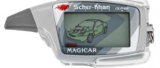
- "Scher-Khan". Manufacturer – South Korea, developer – Russia. The cost is in the range of 7-8 thousand rubles. Connection via mobile phone and Bluetooth is possible.
- "Alligator" American security system. Cost up to 11 thousand rubles. Diverse model range.
- "Sherriff". Manufacturer – Taiwan. Budget models are presented, costing 7-9 thousand rubles.
- "Black Bug" Russian manufacturer. The lineup includes both budget and premium models.
- "Ghost" Russian manufacturer of alarm systems with a wide range of models. Prices range from 6,000 to 27,000 thousand rubles.
A car alarm helps protect your car from theft and burglary. Modern security systems provide a fairly high degree of protection. The driver also has many other useful features. An alarm system is a necessary and mandatory thing for every car.
Tips for choosing an alarm:
types of car alarms, buy car alarms with feedback and auto start
1) When choosing an alarm, focus on where the car is stored (near the house or far away in the garage). In this case, the range of the alarm and what kind of communication is important - one-way or two-way. There is no need for a siren if the car is stored in a guarded parking lot or garage.
2) For cars located near the house, an alarm system with a pager, with a coverage area of 300-500 m, a siren and lights is suitable.
3) It is safer to choose alarms with a large number of sensors, but a tilt sensor is relevant if your car has expensive wheels, or you are very afraid that they will be removed.
4) Alarms with CAN and GSM modules are very useful, but due to the considerable cost they are installed on expensive cars, and are supported mainly by foreign cars.
6) Do not throw away the instructions for use and with a description of the alarm system and store it, because it will be useful in case of reprogramming or repairing the alarm system, and if you have questions during operation, you can always find the answers in the instructions.
7) Remember or write down the brand and name of the alarm system, but do not stick its name on the windows or body.
8.) Remember:
- Where was the alarm system unit installed;
- Location of the jack button and adjustable shock sensor;
- Blocked circuits.
9) The batteries in the key fob should be changed on time.
10) It’s not bad to have 1-2 more spare key fobs, in case one is lost or several people use the car.
11) Insurance companies and car dealerships often make duplicate key fobs so that they can confiscate the car in the event of your lack of creditworthiness, so we advise you to install the systems from different specialists.
So now you know which alarm system is best to install on your car and following our advice, we think you will make a worthy choice!
If you liked the article, share it on social networks and leave comments!
Engine blocking with car alarm
If there are installed anti-theft systems, electrical equipment is responsible for blocking the engine start. Immobilizers or car alarms may be faulty and cause constant or occasional failures during operation.
It should be added that the severity of the problem will depend not on the specific model or brand of car, but on the complexity of the installed anti-theft security system.
Accidental activation of the engine lock function
First of all, carefully study the displayed icons on the alarm key fob. A common cause of blocking is accidental activation of additional functions. It is also necessary to monitor the readings of the LED indicator light (if equipped) in the vehicle interior, which serves as a light indicator of the alarm status. Flashing LED lamps in most cases indicate that the anti-theft function of the immobilizer is activated in the menu.
If, after turning the key in the lock and turning on the ignition, the warning lamp blinks frequently (for example, the StarLine car alarm) before starting the engine, and a pictogram with the inscription “immo” is displayed on the key fob itself:
- One way to solve the problem is to remove the key from the lock, after which you just need to press the button to open the central door lock on the key fob.
- You can also get out of the car, set the alarm to security mode, then disarm it and then start the engine.
In other words, you need to make sure that the alarm operates in the normal mode that is familiar to the owner. Up to 30% of cases of engine start blocking by alarms occur due to accidental changes in program settings. The driver’s task is to disable all unnecessary functions in the settings.
Using the StarLine alarm as an example, let us note that this system has the option of “two-stage” unlocking. Activation of the function may occur accidentally; a separate icon will light up on the key fob screen
To turn it off, you must hold down button 3 on the key fob. The key fob will emit two beeps, after which button 3 is pressed once again. Then button 1 is pressed for a few seconds, then the security functions are removed;
Preparing for installation
The installation consists of two stages.
| Stages | Actions | Additional work |
| The first involves preparing the car for installation of locks. | At this stage, you need to check all the doors and pillars for all the necessary holes and channels where the wiring will be laid. | If the conditions necessary for installation do not exist, they will need to be created: make holes and install fasteners. |
| The second stage is the installation of locks. | The mechanisms are installed on the already prepared car and the wiring is laid. If the preparation for this was carried out in compliance with all the necessary conditions, then problems should not arise. | But if you forgot to make a hole or forgot about the fastening, then you will have to postpone the task you started and finish the previous one. |
After you remove the trim and pull out all the interfering insides of the door, you will need to make holes for the wiring. This is an important installation element, and usually only the front doors have them, and not on all models of that car. The rear doors do not have such holes at all, so you will need to make them yourself.
Replacing the limit switch with an alternative one
If a decision has been made not to sculpt the glue from scrap materials, then it is necessary to look for a worthy alternative. Let's say right away that the VAZ 2114 door limit switch can be easily replaced with a similar device with DAEWOO; we will need the General Motors device model 96235956 in the amount of 5 units.
End caps from DAEWOO
We need to replace one limit switch with another, to do this we twist the old one and get to work:
- We start with the rear doors, where the analogs will become like family.
- We move on to the front door, where, due to the fact that our analogue is a little wider, the holes will not match, we will have to screw it in a little diagonally.
- Before doing this, it is necessary to solve the problem with the wiring running along the rack, due to the fact that our device is wider, it will not allow it to work normally. To solve this problem, a heat-shrinkable tube of the required size for the end cap is selected in advance; this will protect it from the cable.
- We assemble and check functionality.
Connecting to wires
Connection to the “four” wires must be carried out in the order indicated above. In this case, you must follow the instructions in the instructions for the alarm. But first you need to place all the alarm elements in the car. Before starting work, turn off the battery power. The device control unit is placed under the dashboard. The siren must be located in the engine compartment. An emergency siren should also be installed there. In the trunk, under the hood, and also in the engine compartment, you need to install limit switches for opening. Place the Valet button in a place hidden from prying eyes. Attach the antenna of the security device to the windshield in the upper right or left corner. Place the shock sensor on a metal surface. Next, the car alarm is connected according to the diagram. To connect it to the central locking you need to purchase the following items:
- 2-3 pieces of 1N4001 diodes for a current of no more than one Ampere;
- One 1N5401 3 Ampere diode;
- Also, some security systems may require two 4-5 Ampere power diodes.
To connect the device to the central locking system, you need to find two wire harnesses on the floor next to the driver's door. To get them, you need to remove the sill trim and side panel. The first harness contains the door switch cable. A 1N5401 diode must be installed in its gap. In the second harness you need to find the wire going to the handbrake, into which you should insert the second 1N4001 diode.
The blue cords of both harnesses must be connected to the car alarm.
Tapping into wires
Next to the driver's door, there are two wire harnesses running right along the floor. One of them has a cable coming from the parking brake and two wires to the turn signals. The second harness contains the door switch cable. This is where you need to start connecting. To do this, remove the sill trim along with the side panel. They are attached using self-tapping screws that must be unscrewed. Having done this, you can see the wiring harness shown in the photo:
This harness goes to the dashboard. We are interested in the door switch cable. If a 1N5401 diode is inserted into the wire break, the current should flow towards the limit switches. And the second diode 1N4001 is connected as shown in the figure.
The following figure shows the second harness:
At the same time, taps are made from the blue cables and the cords are pulled to the place where the alarm will be installed. And the handbrake wire is cut, and a 1N4001 diode is soldered into the cut with the cathode towards the switch.
How to connect
Installation of the VAZ-2114 alarm system begins with disconnecting the battery and determining the location of the elements. The control unit is placed under the instrument panel or behind the glove box, the siren is placed in the engine compartment. Guided by the instructions and diagram, all elements are connected.
The control unit is connected through connectors to system elements, components and vehicle parts. Installation and installation begin from the farthest point of installation of the security system element, using 9 connectors (X) for connection.
Sensors (limit switches) are installed in the engine compartment, under the hood and in the trunk, which react to opening. The door trims are dismantled to install activators. The Valet service button is installed in a place hidden from prying eyes, but easily accessible to the car owner.
A transmit-receive antenna is installed on the windshield in the upper corner. It is recommended to install the shock sensor inside the passenger compartment, securing it to a metal surface. The emergency siren is installed in the engine compartment with the bell facing down.
When all the elements are located in their places, you can begin to connect them into a single system.
Scheme
The characteristics of the Starline A 91 car alarm and the connection diagram of the main elements are given in the manufacturer's instructions. When connecting a 6-pin connector X 2, you may need an additional door opener activator.
When connecting door opening sensors, use the blue/red wire of connector X 3. All alarm connection points, i.e. connectors (X) look like this:
- X 9 - connect a two-level shock sensor installed on a metal surface.
- X 8 and X 7 - connectors are not used.
- X 6 - Valet service button, installed in a hidden and easily accessible place.
- X 5 - LED indicator, installed on the instrument panel.
- X 4 - transmitting sensor receiving module; it is recommended to install it in one of the upper corners of the windshield.
- X 3 - connector with many wires.
They are connected to the systems with wires of the following colors:
- Red - with the “plus” of the ignition switch.
- Green/yellow and green/black - sidelights and side turns.
- Black—vehicle mass.
- Yellow - ignition switch (connection to blue/black).
- Gray is the “plus” of the emergency siren.
- Blue/red - “plus” of the door entrance.
- Black/red - additional blocking relay.
- Orange/gray - hood lift sensor.
- Orange/white - trunk opening sensor.
- Orange/purple - to the brakes (according to the diagram in the instructions).
- X 2 - connect door opening activators;
- X 1 - ignition switch (closed with red wire).
1. Car alarm connection points for VAZ 2107 2008
All connections are made behind the glove compartment.
+ 12 — pink ignition — blue thick ignition 2 — blue/black thick starter — red thick fuel pump — gray, to the relay block behind the glove compartment handbrake — brown charging — brown/white tachometer — brown/blue door limit switches (-) — white/black from the passenger door switch, turns - blue and blue/black, dimensions - yellow/red
Cenmax ST7 works great on the tachometer
Selecting a security alarm for installation on a domestic car
The function of remotely closing and unlocking all car doors is mandatory for all types of modern anti-theft alarms. It is impossible to install an alarm without a central lock, so car owners are forced to install a central lock before purchasing a security system.
The trade offers motorists hundreds of models of anti-theft alarms in a wide price and functional range.
When choosing a car alarm for installation on domestic cars, the main selection criteria for car owners are:
- Affordable security system price. Experienced car enthusiasts do not buy the cheapest anti-theft alarms, doubting their durability and quality of work. Most Russian drivers prefer to buy car alarms from the middle price range.
- System functionality. Ordinary owners of VAZ models consider the car alarm to include a remote key fob, two or three sensors, a siren, and connection cables as a sufficient set of options.
- Possibility of self-installation. To implement this requirement at the purchase stage, you need to be interested in the complexity of the electronic control unit for the security system, detailed diagrams and instructions for connecting the anti-theft alarm. When installing it yourself, minimal disruption to the standard electrical wiring is desirable; it is not recommended to interfere with the operation of existing mechanisms.
Owners of VAZ-made models do not need to worry about the difficulties of flashing factory protections or bypassing standard immobilizers. However, experts do not recommend that novice car tuning enthusiasts begin work by independently installing security systems equipped with:
- remote engine start (remote engine start based on temperature, timer);
- coded dialogue communication system, GSM modules;
- numerous additional options (starting from a smartphone, turning on heaters, air conditioners).
The easiest way to install a simple car alarm with a minimum set of functions on your own.
Practical connection operations
To install a car anti-theft alarm you will need simple tools and materials:
- screwdrivers, wrenches (special pullers are not needed to dismantle interior elements of VAZ models);
- soldering iron and soldering accessories (solder, acid);
- multi-colored single-core cables (selected according to the colors of the standard electrical wiring or the pinout of a specific electrical circuit);
- linear meters and multimeter;
- insulating materials;
- fastening elements (special plastic clips are preferred).
The easiest way to find the central locking control unit is when installing the main car alarm control unit. For example, on the VAZ 2110 it is located rather inconveniently.
During installation, it is convenient to use wires of the same colors as those coming from the central locking control unit.
Having disassembled the door card, you can connect the control wires directly to the electric drive of the lock.
It depends on the car alarm model whether you need to purchase additional relays. Sometimes standard fuses and power switches may not withstand the additional load.
The easiest way to connect a car alarm to the central locks of VAZ models is to solder into the wire breaks (usually white and brown). To do this, you need to lay a four-wire cable from the two internal relays of the alarm unit to the eight-pin connector for controlling the door microswitches.
To avoid oxidation and damage to the integrity of the wires (this leads to false alarms), you must follow simple rules:
- carry out electrical installation work with the battery disconnected;
- connect electrical wiring only by soldering or terminals, insulate connections;
- use cables with a small margin in length, lay them in bundles, and securely fasten them to body elements;
- Observe the color of the cables for easy identification during alterations or repairs.
Central lock designs
Advanced car central locking configurations include:
- Control block;
- electrical supply cables;
- input sensors;
- remote controls;
- actuators (actuators);
- additional devices (window closers, electric sunroof, electric trunk locks, fuel hatch lock).
In basic configurations, the central locking control unit, after turning the key, removes the locks from the locks of all doors, activating the actuators.
The same functions are performed by the car alarm control unit, which is devoid of actuators, so harmonizing two systems built on different principles becomes the main task of the installer.
The basic diagram of connecting electrical circuits is the same for all types of central locks, car alarms, only the design of the control unit, actuators, and the number of pins for connecting additional devices change.
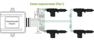
General diagram of connecting the alarm to the central locking
Important elements of the central lock, in addition to the control unit, are door limit switches (“limit switches”) and microswitches that fix the position of the key and locking mechanisms. These elements must be connected to interior lighting and car alarms.
Differences in designs of actuator drives (electric, pneumatic), types of control (negative, positive pulse, variable polarity) are important for understanding the theory. In practical work, the car enthusiast focuses on a specific model of central locking.
Additional alarm functions
In addition to the main security function, some useful additions can be implemented in car alarms. For example, such as:
- Remote engine start. The engine warm-up function is especially convenient in winter. You can start the engine remotely and prepare it for the trip in time.
- Remote control of power windows. The windows are automatically raised when the car is armed with an alarm system. No need to remember if all the windows are closed.
- Car protection when the engine is running. This function is useful when leaving the car for a short time.
- Satellite tracking (GPS/GLONASS). Many anti-theft systems are equipped with active tracking systems via GPS or GLONASS satellite systems. This is an additional level of protection for the car.
- Engine blocking. Advanced versions of security systems can be equipped with a remote engine stop system. Additional vehicle security against theft.
- Control the alarm and other functions from your smartphone. Modern systems allow you to control all functions from your mobile phone. The availability of this option depends on the configuration and model of the alarm. Management occurs through a special application.
Basic information about the car
When starting to install the alarm, you need to understand exactly where and what is located in the car, and what you will connect. Let's look at the connection diagram for the VAZ central locking system:
Central locking control module, connection
The control module is located under the dashboard on the left, and its connector attached to the body contains six wires:
DBMS module of the “ninth” family
When installing an alarm, the “blue” and “brown” cords are broken to obtain the following diagram:
How to connect the alarm to the central locking system
The wiring of the 6-pin connector mounted on the main Starline A91 module is given below. Carefully study the principle of operation of the circuit: the limit switch here is in the “closed” position.
Before connecting the alarm to the ACU, make sure that a standard 5-wire actuator is installed in the driver's door, and not a toggle switch. It’s unlikely that anyone will be able to install the actuator with their own hands by running two cords to the engine in 5 minutes. In general, it is sometimes better to refuse to connect the signaling system to the central locking system.
Let us take the liberty of revealing VAZ’s proprietary secret:
- If you see a "white" control wire connected to terminal "7", it is responsible for unlocking (as opposed to the "brown" one);
- If terminals “5” and “7” are not used, a “brown” cord will be connected to terminal “8”, and it is then responsible for unlocking.
The locking contacts are terminals 5-6. The two outer terminals are responsible for unlocking. This is true not only for model 2114, but also for BUBD units of the “ninth” family in general.
The instructions for the alarms usually do not say that you will need to buy additional parts before installation. These include:
- Diodes 1N4001 (2-3 pcs.) – designed for current up to one Ampere;
- 1N5401 (1 pc.) – three-amp diode;
- To install any car alarm that does not have separate outputs for turn signals, you need to purchase two power diodes (4-5 Amperes).
The latter, as you might guess, does not apply to the Starline A91 system. And this is great luck.
1N5401 diode wiring
When installing any Starline system, you usually spend less than 100 rubles on parts.
Lock connection diagram
In order to be able to install central locking on VAZ cars, the manufacturer equipped them with a special BUBD control module. You can find it directly under the torpedo, on its left side. If this module is missing, it will simply not be possible to install the device, so before you buy an electronic lock, you should first find out whether the module is installed on the car.
Control module
The connectors of this module are equipped with 6 wires of different colors as standard. If you are installing an alarm system on a VAZ 2114, you will need to turn off brown and blue in order to get the following connection diagram:
Before you begin installing the lock, you should make sure that five-wire actuators are installed in the car doors. If it turns out that ordinary switches are installed instead of them, then it will not be possible to connect the alarm.
Another important point to remember is the need to purchase additional electronic components that are not included in the alarm kit.
These include:
- diodes 1N4001 for 1 Ampere - 3 pieces;
- three-amp diode 1N5401;
- any diode rated for a current of up to 5 Amps (only if there are no separate outputs for turn signals).
Diode wiring
Once these components have been purchased, you can begin connecting the alarm. To do this, you should carefully study the drawing with the connection plan included in the instructions (this diagram of the VAZ 2114 central lock is duplicated below) and carry out the entire installation procedure in accordance with it. So, in the diagram, the index X2 indicates the six-pin control connector (BUBD), which was mentioned at the beginning. This is where you should start connecting, guided by the same “native” circuit.
After the lock is connected, all that remains is to insert into the wires in order to connect the alarm to the door sensors.
Connecting door limit switches VAZ 2114
It is done in the following order:
- Remove the sill trim along with the side panel by unscrewing their fastening screws.
- In the exposed wiring harness, find the cable going to the door limit switches (it has a white and black color) and solder a 1N5401 diode into its gap so that the direction of possible current flow is only towards the limit switches.
- In the second wiring harness, find two blue cables, from which you should make taps (using a wire of the same cross-section) and stretch them to the location where the alarm is attached.
- Cut the handbrake wire and solder a 1N4001 diode into its gap with the cathode towards the limit switch.
Tapping into wires
If necessary, you can make an insertion into the wires even before connecting the alarm to the connectors - this will not affect the functionality of the electronic equipment in any way.
The next step is to connect autorun. To do this, you will need to power the alarm to terminal 30 of the ignition switch, and connect the yellow cable coming from connector X1 to its 15th connector (according to the connection diagram).
After the alarm is connected to the on-board power supply, you will need to connect it to the speed sensor by connecting the gray-black wire coming from connector X3 to the tachometer. After this, all that remains is to connect the black wire X3 to the ground connector in the main unit.
At this point, the installation of the central lock can be considered complete.
Settings Features
Many motorists are naturally interested in how to properly adjust and configure the shock sensor provided on the car alarm.
Each car alarm installed on modern cars has approximately the same setup principle. The adjustment involves changing the sensitivity up or down. That is, we adjust the alarm system’s response mode depending on the vibrations detected by the sensor.
Once you have installed a shock sensor on your car to complement the alarm, it needs to be configured upon first start-up. The only question is how to do it correctly. You can make adjustments yourself or seek help from adjustment specialists.
There are different types of security systems for cars. Depending on the specific model, configuration can be done in 2 ways:
- manually;
- via computer.
The manual method is the easiest. Some sensors have a special lever or knob on the body, the rotation of which allows you to change the sensitivity parameters. According to the instructions, read what impact power this or that scale on the sensitivity regulator means.
Computer setup is more complex. To do this, you will need to connect the laptop to the device using a special cable. Usually it comes complete with an alarm. Sometimes you have to buy it separately.
Through special software, which is usually proprietary to each alarm, you need to select a menu with device settings, go to the sensitivity section, adjust the sound and trigger mode.
When adjusting the parameters, select the settings you need, turn on the alarm, try to strike. But it is better to conduct such experiments during daylight hours and at a sufficient distance from residential buildings. It’s unlikely that your neighbors will like it if you start experimenting with the volume of your alarm in the evening.
Shock sensors are indeed a useful addition to car alarms. This is an auxiliary security element that responds to direct contact of a potential attacker with the vehicle. Yes, the sensors are not perfect, and can work erroneously, reacting to the fall of some objects, jumping animals, or banal pranks of children in the yard.
But it is not recommended to disable shock sensors. Depending on the situation, you should select the appropriate sensitivity level. Near a noisy road or when there is constant traffic around a parked car, it is better to reduce the sensitivity. If the place is quiet and calm, but potentially dangerous for the car, then it is better to raise the sensitivity.
To install any alarm system yourself, you should study its instructions in detail.
In our example, we will look at the installation of an alarm model Starline A91.
Alarm systems from this company are perfect for installation on VAZ -2114 and VAZ -2115 cars
Before installing an alarm on a VAZ - 2115,2114 car, you need to have a good understanding of the car's structure, and also decide what to connect to the alarm.
Car alarm installation
Before purchasing, study all kinds of models, select the ones that are suitable for the VAZ-2109.
Check for these features:
- turning on the engine from the key fob;
- remote engine stop;
- mechanical impact indicator;
- communication and communication signaling device;
- turning on the alarm whenever the car is opened;
- possibility of canceling the program.
Instructions are included with each device. If you install it yourself, you need to familiarize yourself with it carefully. Even after a high-quality self-installation, there may still be some nuances. For example, a monolithic alarm system is easier to install, mobile, it will not be difficult to install it anywhere on the car, but it is easier to hack if it is stolen.
To install this device, you will need the following devices and tools: a voltage meter with limit data up to 12 V, insulation, Phillips and regular screwdrivers, a wire stripper, a soldering iron, single-core and stranded wires (length up to 10 meters).
Door limit switch VAZ 2114: use, modernization and replacement
Limit switches - also known as limit switches - are electromechanical devices whose task is to open/close an electrical circuit. Although the device was originally developed for use in engineering structures, but with the increase in the number of electronics in vehicles, they began to be widely used in their control system.
So, since the 50s of the last century, almost all cars were equipped with an automatic system for turning on the light in the cabin when the front door was opened, but with the progress of progress, an increasing number of tasks began to be assigned to the limit switches used in the car, for example, the limit switches of the VAZ 2114 are located on the entrance doors and trunk.