The ignition module on the VAZ 2114 8-valve injector and on other VAZ models is designed to supply high voltage through the PVN to the spark plugs. Some car owners call the ignition module a coil, which is not entirely correct.
Ignition coils were installed in carburetor vases. The VAZ 2110-15 uses the ignition module. Let's look at the functions of the ignition module, operating principles, circuits, and signs of malfunction.
Main function of the ignition module
The main task of the module is to supply current to the spark plugs. During operation, a working spark is supplied to one spark plug, and an “idle” spark is supplied to the other. The working spark is supplied to the 1st and 4th cylinders, and the idle spark is supplied to the 2nd and 3rd. Due to this connection, the spark appears in a timely manner in the desired cylinder during the required stroke. It is connected to the on-board network.
Checking module 2114 using improvised methods
- There is a reliable way to determine that the ignition module is faulty. You need to take a working module and try to start the engine on it. Not every module may be suitable. If you are lucky and the engine is working, this means we send our module to the trash heap and install a new one. In addition, there is a fairly high probability that there is damage in the high-voltage wires and this will not only prevent us from testing our hypothesis, but may also damage the donor ignition module. This means that before checking the module itself, you need to make sure that the high-voltage wires are not damaged, do not break through to ground, and hold the current well.
- Checking the high-voltage circuit of the module for an open circuit. To do this, you need to take a micromultimeter and set it to resistance measurement mode. In the ignition module, the ignition coils are connected in parallel - the first with the fourth, the second with the third. To check, take a micromultimeter and install the probes into the connectors for high-voltage wires on the module when the ignition is turned off. First the 1st and 4th, then the 2nd and 3rd cylinders. The resistance between parallel coils should be 5.0-5.6 Ohms. If the resistance is infinite, then the network is broken and the module must be replaced.
- There is also an old-fashioned way of checking - to hit it well. This may help wake him up for a while, oddly enough. And it will give you time to pick up a new part at an auto parts store.
Operating principle and location
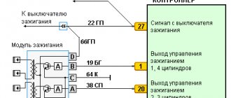
The ignition unit is controlled by a controller, which in turn receives information about the state of the vehicle from various sensors (IAC, DMRV and others). The controller also sets the sequence of operation of the ignition coils or, in other words, regulates the supply of current to the spark plugs. The ignition module operates at temperatures from -40° to +130°.
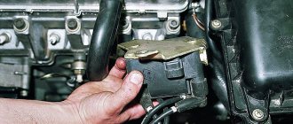
Finding its location is not difficult; high-voltage wires (HV) go from the module to the spark plugs; along them you can find it.
Signs of breakdown
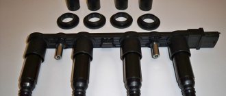
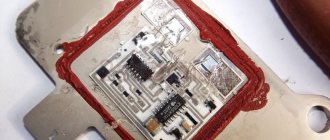
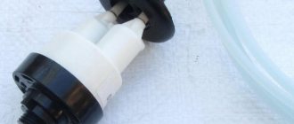
Disassembled
In fact, the symptoms of a malfunction in the VAZ 2114 ignition module are in many ways similar to the breakdown of other units. For example, you may observe the following phenomena:
- The engine is tripping;
- The car stalls at idle;
- There are problems when trying to start the car, etc.
That is, in fact, it may not be a module at all. Therefore, the only correct solution is to check the ignition module on your VAZ 2114.
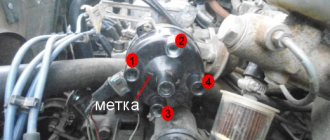
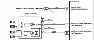
Diagram of the correct connection of wires to the ignition module
If, after checking the wires, you are convinced that they are all tightly connected to the spark plugs, make sure that they are connected correctly. Of course, if no one has climbed into the engine before you, then there is no point in checking. If there was traction and it disappeared, the reason could be both in the coil and in the wires themselves (if they break through). But in any case, let's check that the connection is correct. The ignition module shows the numbering of the cylinders to which the wires fit.
- 1 cylinder – central lower outlet
- Cylinder 2 – left output
- Cylinder 3 – top outlet
- 4 cylinder – right output
The diagram is shown for a coil installed on a vehicle.
If after checking no problems are identified, you should consider replacing the coil or wires. It is advisable to change both.
The cost of PVN, depending on the manufacturer, ranges from 300 to 600 rubles per set. The most popular manufacturers:
- TESLA
- BRISK
- BAUTLER
- Egorshinsk
The cost of an ignition coil is from 1300 to 2500 rubles. Modules from the following companies can be found in stores:
- SOATE (St. Oskol)
- MZATE
- HOFER
- FENOX
- BOSCH
When choosing a module, you should pay attention not only to the manufacturer, but also to the coil itself; it comes in old and new designs. Therefore, it is better to dismantle yours and bring it to the store.
Ignition module 2114 - causes of malfunction
The main point that you should pay attention to when the ignition module breaks down is unstable floating engine speed, jerking when driving, indicating that the engine is running rough, difficult starting of the engine or it refuses to start at all, the “Check Engine” light on the dashboard comes on, the description of which We have done this more than once on the website provaz2114.ru, these are the main signs of failure of the ignition module.
Causes of malfunction
Carrying out diagnostics yourself is quite difficult, because the ignition module of the VAZ 2114 8 valves includes several devices, despite the fact that it is made of one plastic case. It is simply impossible to check all devices separately without special equipment. But this does not stop experienced car enthusiasts. At least, if not repaired, then it is quite possible to detect signs of a malfunction in the ignition module on a VAZ 2114 using improvised means.
Checking contacts
- Firstly, before you start repairing the most important part in the ignition system of your iron horse, you need to find out what exactly is not working there.
- Immediately check the quality of the contacts of all blocks of the low voltage circuit, and also look at the contacts of each high voltage wire.
Checking the power supply to the ignition module
How to check the ignition module of a VAZ 2114 injector 8 valves?
- To do this, we determine whether there is power supply to it.
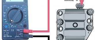
- To do this, you need to take the connector in the block and find the contact marked with the letter A.
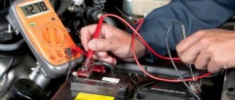
- To measure the module's power supply, take a micromultimeter, select the AC measurement mode up to 20 V, apply the negative probe to the engine ground and turn on the car's ignition.
- We apply another probe to contact A on the block.
- If the electrical equipment is fully operational, the micromultimeter will show 12 V, this means that power is supplied to the module, we look further for the cause of the malfunction.
Checking the connector contacts
Using this test, we were able to verify that power was supplied to the ignition module. This means you need to check each contact separately.
- Turn on the ignition, take the test lamp and connect it to two contacts at once: contact A and contact B.
- The control indicator can be made from a 12-volt low-power lamp with pre-soldered contact wires, or you can use a 12-volt automotive test probe with a voltage indication.
How to check the ignition module with a lamp on a VAZ 2114?
- We apply the contacts of the test lamp or probe to outputs A and B, then turn the engine starter.
- If the light flashes, the ignition module breaks the contacts as if it were a contact breaker. This means that contacts A and B are in perfect order.
- If the light never blinks when the starter starts, the ignition module is faulty.
How to check the malfunction of the VAZ 2114 ignition module on your own?
The easiest way to check the device without removing it is to diagnose it at the moment the power unit is tripped. When the motor begins to operate unstably, it is necessary to disconnect the connector elements from each component of the module one by one. If the connector is disconnected from a functioning device, the operation of the engine will change. Dips will appear, and the unstable operation of the unit will increase. When the non-working element of the MH is disconnected, the motor will operate in the same way.
There is another simple diagnostic method, its principle is as follows:
- You will need an assistant to check. The spark plug is removed from the seat. The high-voltage cable is disconnected from the device.
- Then the disconnected wire is connected to a spark plug, which is applied to the body of the power unit.
- The machine motor is starting, you need to make sure that a spark hits the spark plug. If it passes, a blue light will appear between the device and the surface of the power unit, its formation is accompanied by a crackling sound. If there is no spark, then the spark plugs, high-voltage cable and module must be diagnosed.
In the absence of special equipment, diagnostics of the MH can be performed using a control light indicator designed for 12 volts. One conductor from the lamp is connected to the pin of connector A, and the second is connected to ground for grounding. An assistant must start the power unit or rotate the starter mechanism. If the light flickers when performing these steps, then the device is working. Similar actions must be done with another contact.
The channel “Diary of an Auto Electrician” spoke about self-diagnosis of ignition modules, as well as other elements of the system.
Checking the ignition unit with a multimeter
Diagnostics is carried out in the following order:
- The car engine is started.
- The tester switch must be set to DC measurement mode, the limit should be up to tens of volts.
- One of the contacts of the multimeter is connected to connector D on the coil, and the other goes to ground. You can use a car body or a cylinder block as a mass. If there is power, the diagnostic tool display will show 12 volts.
- Then the tester switches to the ohmmeter operating mode, the range of values is up to tens of ohms.
- One contact of the diagnostic tool is connected to output C, and the second goes to ground. If the device is operational, the test will show a value of less than 1 Ohm.
- At the next stage, the tester must be switched to voltmeter mode. The range of values is up to tens of volts.
- One of the contacts goes to the output marked B, and the second is connected to ground.
- If the diagnostics show that the voltage is less than 0.3 volts, then the device is working. This indicates a clear signal passage from the Hall controller. Finally, you can perform a similar test, only with connector A. The results should be identical.
Direct check of secondary coils for breakdown
To diagnose secondary elements of the MH for breakdown, you will also need a tester:
- All connected conductors must be disconnected from the device connectors.
- Diagnostic equipment is set to ohmmeter mode, the range of values is up to tens of ohms.
- The contact probes of the tester must be connected in turn to the paired connectors of the module. For example, in the second and third, as well as in the first and fourth.
- If the diagnostics showed the same results, then all windings are operational. The resistance parameter should be about 5.4 kOhm. If the values obtained are higher, this indicates an internal break in the device. With lower parameters, we can conclude that there is a breakdown.
Video “Visual guide to replacing MH”
The STO TONN channel presented a visual aid for replacing the ignition module on a domestic VAZ 2114 car.
They brought a “wonderful” car to our service center, as the owner put it. And the miracle is that the owner declares: he changed EVERYTHING, the car worked on two cylinders and still works. We ask how they discovered that two cylinders were not working? The owner replies: I checked the spark, there is no spark on the second and third cylinders. I installed new wires, installed a new ignition module for testing, even installed new ECUs (brains), no spark in 2nd and 3rd and that’s it. The wiring says they checked it, everything is fine, there are no short circuits. Well, truly MIRACLES.
Here it is, our wonderful machine! VAZ 2114
Fig.1
Let's start in order. We connect diagnostic equipment and read errors, if of course there are any. We have several of them. We have installed the control unit January 7.2
Replacing ignition module 2114
How to check
The resistance between contacts 1 and 4, 2 and 3 should not exceed 5.8 kOhm
, Having found a multimeter at home
Multimeter
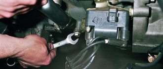
I went to the car, removed the ignition module by unscrewing 3 bolts and began to measure the resistance... and then it turned out that the module was long overdue for replacement...
Resistance between 1 and 4
Resistance between 2 and 3
Horrified, having installed the module, the store went back. Upon arrival at the store, they offered a choice of 2 reels, one of them was made in Russia and the other was made by Bosch Germany, the difference in price was a little more than 1000 rubles... At that time there were problems with finances, so I had to buy something cheaper
Having put the new module in place, the car simply whispered (I made 3 laps around the area with pleasure)
How to replace
Jerks when accelerating
A module failure does not always result in a complete failure of two cylinders. Often the MH begins to “die” gradually, alternately working without failures. If dips and jerks are noticeable during the movement (especially when accelerating), then the following procedures should be carried out:
- Check the fuel level;
- Make sure that the fuel filter is not clogged and that the fuel pump is working properly;
- Listen to the engine idling.
The cause of failure during acceleration may be a faulty throttle position sensor, air flow sensor or mass air flow sensor. Also often the cause of failure when accelerating is the MH.
This is explained by the same reason: at the moment of module failure, a misfire is observed in two cylinders, which does not allow the full power of the unit to be realized. Without diagnosing the unit with a multimeter, it will be difficult to determine the serviceability of the MH, so install a known working element and drive the car again.
Accurate diagnostics and identification of breakdown symptoms allow the driver to independently repair faulty components. The ignition system in the “four” is quite simple and not loaded with unnecessary components, so even a novice driver will not be difficult to identify a module malfunction based on the symptoms listed in the article.