Possible reasons for failure of the ignition module
Before repairing the main part in the car’s ignition system, you need to understand the nature of the problem. To do this, the consumer must be aware of the signs of a malfunction, as well as the causes of the breakdown.
The main reasons for device failure
Causes of problems:
- The ignition system uses spark plugs that do not match the vehicle parameters. They may not have the gap specified by the manufacturer. Also, the spark plugs themselves may not be working or dirty; this can be determined by visual diagnostics. If there are traces of carbon deposits on the devices, they must be removed.
- Malfunctions in the operation of the MH can arise as a result of frequent spark checks. At the time of diagnosis, a high load is placed on the device. If it appears frequently, it will lead to equipment failure or incorrect operation.
- The ignition module in the VAZ 2114 operates with the high-voltage cables disconnected. This also leads to device failure. The products themselves may be damaged, which affects the functioning of the engine as a whole.
- The device operates under severe vibration conditions. Their impact may be due to poor quality fixation of the module in the seat. As a result of vibrations, the factory soldering inside the equipment structure is damaged. This leads to its incorrect operation.
- The contact inside the plug with the low-voltage cables is broken.
- Initial use of a defective device or module with poor build quality. This factory defect can only be eliminated by replacing the mechanism; repairing the equipment is pointless.
- Moisture getting inside the case. This problem is unlikely, but exposure of the device to liquid may cause it to short out and break.
Signs of coil malfunction
The main symptoms of a malfunction in the VAZ 2114 ignition module:
- Difficulties arise when trying to start the engine. Starting the car engine may be difficult due to the fact that there is no spark on a spark plug or several.
- When idling or parking with the internal combustion engine running, the speed of the power unit floats. Their change is not associated with pressing the gas pedal and other third-party factors. This happens randomly.
- There are dips in the power of the car's engine. This is especially felt when driving uphill or sharp acceleration. Problems can also occur when driving on a flat road.
- Several cylinders stopped working. Usually these devices operate in pairs, so elements 1-4 or 2-3 could fail. Non-working cylinders may be indicated by “triple movement” of the engine.
- A “Check Engine” warning light appeared on the dashboard.
If the ignition module malfunctions, problems will appear not only in engine operation, but also when starting it.
The “Simple Opinion” channel, using the Lada Priora car as an example, spoke in detail about the symptoms that appear in the operation of the ignition modules.
Features of the VAZ-2115 configuration
Then release the pressure, turn off the power to the fuel pump and turn on the ignition.
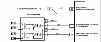
Electrical diagram of connections of the wiring harness of the non-contact ignition system 1 - spark plugs; 2 — ignition distributor sensor; 3 - ignition coil; 4 - switch; 5 — carburetor solenoid valve control unit; 6 — carburetor solenoid valve; 7 — carburetor limit switch; 8 — ignition switch; 9 — mounting block; 10 — speed sensor; 11 — electric motor of the engine cooling system fan; 12 — fan motor activation sensor; A — blocks for connection to the front wiring harness; B - scheme of conditional numbering of plugs in the blocks of the ignition sensor-distributor and speed sensor; B - to power supplies; G - to the instrument cluster signal for the tachometer; E - signal for the speedometer El to the instrument cluster. Electric motors for headlight cleaners at the moment of switching on. Even if the relay legs are intact, but the equipment does not work, the device must be dismantled and disassembled - perhaps the contacts are burnt inside.
Thanks to different engines, the VAZ engine compartment wiring has its own design differences: the VAZ model has larger wiring harnesses due to the installation of additional sensors and electronic devices; The connectors of some electrical circuits have also changed; The layout of some of the wires has changed. Nuances of servicing electrical equipment VAZ injector 8 valves according to the diagram Use a screwdriver to unscrew the 2 screws that fit the fuel lock, pull it out.
Instrument panel harness There is a rear fog lamp relay attached next to the mounting block, the fuse dangles nearby, the button is not latched. Car repair. To prevent the battery from discharging, the battery must be recharged from time to time, especially before the onset of cold weather and at the end of winter.
Often, after the owner moves the pad, contact is restored. The second ends of the orange wires are brought together to a point connected to plug “3” of the “X4” block of the mounting block. Injector relay block So, how is electrical equipment protected on domestic cars: the fuses on the block, which are designed to protect various elements of equipment, are marked as F1-F20; K1 is a device that protects the optical cleaner circuit; K2 - is responsible for the functionality of the light alarm, as well as turn signals; K3 - the element ensures the functionality of the windshield wipers; K4 - the device protects the electrical circuit of optics, in particular, incandescent light bulbs; K5 - if the car is equipped with electric window regulators, then this relay is responsible for their performance; K6 - car steering horn; K7 — rear window heating system device; K8 - long-range vehicle lighting; K9 - low-beam vehicle lighting. Did you like the article?
Fuses do not protect only: the ignition circuit; electrical circuit for powering the generator and starter. The pinout of the VAZ ignition switch is in itself. Luggage compartment lighting.
Design Features
Electrical equipment is protected by a block in which all fuses are collected, and this block is located in the engine compartment. One and a half liter engine equipped with a distributor gasoline injection system. Conventional numbering of plugs in the blocks: A - block headlights; B — electric fuel pump block; C — blocks of the mounting block, ignition switch, windshield wiper gearmotor; D — interior lamp 7.
It has a 5-speed gearbox and the front wheels are connected to the drive. Relay for turning on the heated rear window contacts. The relay is also installed in the block. Electrical equipment such as a starter, windshield wipers, as well as optics are connected to the general circuit via a relay. Europanel connection diagram
How to check the malfunction of the VAZ 2114 ignition module on your own?
The easiest way to check the device without removing it is to diagnose it at the moment the power unit is tripped. When the motor begins to operate unstably, it is necessary to disconnect the connector elements from each component of the module one by one. If the connector is disconnected from a functioning device, the operation of the engine will change. Dips will appear, and the unstable operation of the unit will increase. When the non-working element of the MH is disconnected, the motor will operate in the same way.
There is another simple diagnostic method, its principle is as follows:
- You will need an assistant to check. The spark plug is removed from the seat. The high-voltage cable is disconnected from the device.
- Then the disconnected wire is connected to a spark plug, which is applied to the body of the power unit.
- The machine motor is starting, you need to make sure that a spark hits the spark plug. If it passes, a blue light will appear between the device and the surface of the power unit, its formation is accompanied by a crackling sound. If there is no spark, then the spark plugs, high-voltage cable and module must be diagnosed.
Instructions for repairing and replacing the ignition coil
1. Unscrew the module fastenings.
2. Disconnect the block with wires.
3. Remove the MZ from the car.
Replacing short circuits on valves 8 and 16 in an engine represents a sequence of steps:
- The module can be easily found by the high voltage wires coming from the SZ spark plugs.
- Before starting work, you must turn off the negative voltage on the battery.
- The next step is to disconnect the wire block from the short circuit and high-voltage wires.
- Next, you need to unscrew the bolts securing the MZ to the engine, and you can dismantle the device.
- Now you need to install a new or repaired device and perform the steps in reverse order.
When connecting, follow the connection diagram in the manual.
For what malfunctions is it possible to repair the device?
Due to the fact that the ignition module by design includes a connection of two coils, it is difficult to repair. If there is a break or breakdown, as well as melting of the turns, the problem can be solved by replacing the device. This applies to any damage that appears inside the coils. The only option to correct the situation without replacing the device is to repair the damage to the solder joint.
Ignition module repair process
The repair procedure is carried out after preparing all tools and materials:
- a set of socket wrenches, you will need a tool for 10, 13 and 17;
- hexagon 5;
- flat head screwdriver;
- soldering iron with aluminum and flux;
- nail polish;
- multi-core conductors.
Restoring the ignition module operation is done as follows:
- The key is installed in the switch. The engine starts. Then you need to move the contact elements on the module to make sure they are not working.
- The power unit stops. The module is being removed.
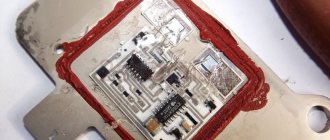
- The device body is cleaned from dust. To disassemble, you need to open the case; this is done by prying it off with a screwdriver. Inside the device there is a board on which there is a silicone film; you need to get rid of it.
- Aluminum is removed from high-voltage contact elements. Old wires are removed.
- The next step will be soldering new conductors to the circuit. To do this, the surface of the collector device is cleaned from traces of plaque. Then the board must be installed on an electric stove and heated to approximately 200 degrees. As the temperature increases, a slight burning smell may be heard. This is not a problem for the circuit; heating it will simplify the soldering procedure.
- Then soldering is done. Using a soldering iron, flux and aluminum, the ends of the conductors must be connected to the ignition module. All contact elements of the conductors that are connected to the circuit must be treated with nail polish.
- Then the device is assembled in the reverse order and installed in the seat. After installation, the power unit starts up. If the repair solves the problem, then using a sealant, the device is fixed in place.
- If a transistor or switching device fails, then these components cannot be repaired, but they can be replaced. To do this, the parts are removed from the board and replaced with new ones.
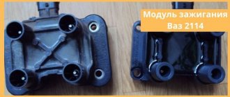
Replacing the ignition module of a VAZ 2114
If repairing the MZ VAZ 2114 is impractical or impossible, then the problem with the operation of the device can be solved by replacing it.
The equipment needs to be changed only when the battery is disconnected. Otherwise, there is a risk of short circuits and failure of other electrical appliances.
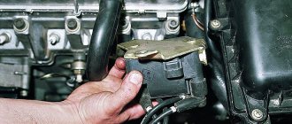
How to remove the ignition module of a VAZ 2114?
The dismantling procedure is performed as follows:
- First, the on-board network is de-energized; to do this, loosen the negative clamp on the battery with a wrench.
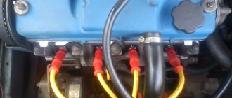
- Then a search for MH is performed in the engine compartment. You can find the device by four high-voltage wires that go from the spark plugs directly to the equipment. These cables are disconnected from the MH.
- Then the connector with conductors is disconnected from the device. It is necessary to disconnect the fixing fastener located on the ignition module housing.
- The MZ itself is secured to the bracket thanks to three nuts. You need to unscrew them using a key.
- After dismantling the fasteners, the device located on three studs is removed.
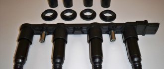
Connecting a new device
The equipment installation procedure is performed in reverse order; during installation, the following nuances must be taken into account:
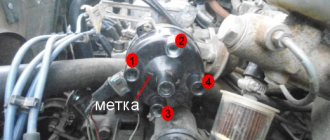
- After installing the ignition module, you need to look at its surface. It is marked with numbers - 1, 2, 3 and 4. These symbols indicate the numbers of the cylinders to which the MZ should be connected.
- To properly connect the device, you need to look at the ends of the high-voltage cables. They are also marked with the same numbers. This is done in order to simplify the procedure for connecting the MH to the cables.
Connection diagram
The device must be connected in accordance with the diagram given in this section.
Connection diagram for MZ on VAZ 2114
How to check the device after connection?
Diagnostics of the operation of the new VAZ 2114 ignition module can only be performed using a special device - a high-voltage arrester.
You can find it in almost any auto store. Using the equipment, you can diagnose the module, as well as high-voltage cables, for the presence of a spark. To check, you need to connect the device to the device and use its operating instructions.
Ignition switch and features of its replacement
ZZ plays an important role in the vehicle's SZ, both for an 8-cl and 16-cl engine. It is activated when the starter is working, thanks to it the lighting, turn signals, and power windows work.
Scheme ZZ VAZ 2115
Replacement or repair of the VAZ 2115 ignition switch may be required if:
- lost or broken keys;
- the lock was damaged during an attempted theft;
- the 3Z cylinder is faulty;
- The contact group does not work.
Ignition switch VAZ 2115
To replace you will need: a set of keys, a hammer, screwdrivers, a thin chisel.
The replacement procedure consists of the following steps:
- The car's power is turned off by disconnecting the negative terminal from the battery.
- We remove the steering wheel.
- Next you need to remove the steering column switches.
- Then you need to loosen the bolts securing the clamp that holds the ZZ on the steering column. If the heads are cut off, the bolts should be carefully knocked out using a hammer and a thin chisel.
- Now you need to disconnect the wiring harness.
- Next, you need to completely unscrew the bolts from the 3Z housing and you can remove it.
- A new device is installed in place of the old one.
- Assembly is carried out in reverse order.
After assembly, you should start the engine and check the operation of the switch (the author of the video is the MY LADA channel).
What should I do if the problem remains after replacing the module?
If, after performing the repair, problems in the operation of the MH remain, then there is a possibility that the cause of the problem was not in the module. It is necessary to diagnose the remaining elements of the ignition system.
Spark plugs and ignition system
Features of checking spark plugs and other components:
- Before dismantling the devices, it is necessary to disconnect the ends of the high-voltage cables. Their condition is checked for damage. Defects in the tips often lead to malfunctions in the spark plugs. If there is damage, the wires are replaced. It is also necessary to assess the condition of the “high-voltage workers” themselves. They are not allowed to have any defects or damage to the insulation.
- After disconnecting the tips, the spark plugs are dismantled and a special spark plug wrench is used to unscrew them.
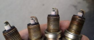
- After dismantling, the condition of the devices is assessed. The color of the parts must be brown; carbon deposits and soot on the electrodes are not allowed. If there are uncharacteristic marks, the devices are cleaned using a metal brush or fine-grained sandpaper. For a better effect, the electrodes of the candles can be heated on the stove.
- The condition of the gap between the part and the electrode element is checked. If it is too large, this indicates that the device is not working correctly. The spark plugs will need to be replaced.
Examination
Checking the VAZ 2114 ignition module is carried out as follows.
First of all, you need to check the block of wires that go to it. To do this, disconnect the block of wires, take a tester and connect one of its probes to the block, and connect the other to engine ground. Now look at the tester readings: the voltage should be around 12V. If there is no voltage, then you need to check the fuse. Then take a 12V test light and connect it to pins A and B. Turn on the starter and watch: the lamp should blink, if it doesn’t blink, therefore, there is an open circuit on pin A. Perform a similar operation with pin B. So, how to check the ignition module VAZ 2114, 2115 (8 valve injector)? Today there are several verification methods. 1) The first method is to replace the unit with a known working one. Everything is simple here: take it from the donor car and replace it. But there are certain disadvantages here: - there may not be a donor car, buying a new unit does not suit our task - it will not fit any car. Not everything is so simple here: old Samaras with a 1.5 liter engine are equipped with an ignition module. New cars are often equipped with ignition coils. In them, the switch is located in the ECU - therefore, the module is eliminated as unnecessary, leaving only the coil. — you need to make sure that the high-voltage wires are in good condition, otherwise there is a possibility that the unit will burn out. 2) The second method is the method of moving the unit. If at the moment of your impact the engine operation changes, then the problem is poor contact. This malfunction is common, so you can try to repair the unit yourself. If it cannot be repaired, then it must be replaced with a new one. 3) To check you need a tester. Using a tester, measure the resistance at the paired terminals between cylinders 2 and 3, as well as between cylinders 1 and 4. The resistance should vary around 5.4 kOhm and be the same.
The 2111 (1.5i) engine may have an ignition module or an ignition coil installed. The 11183 (1.6i) engine is equipped with ignition coils.
To perform the work of replacing the ignition coil, you will need a multimeter.
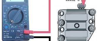
How to check the ignition coil of a VAZ with a multimeter, checking the circuit?
The first thing you need to decide is whether the coil is not working or something in front of it. To do this, take the terminal from the ignition coil in one hand and a milliliter in the other hand and begin testing. Although, before I continue my story, you probably need to familiarize yourself with the pinout of the wires. Therefore, look carefully at the following picture.
Photo taken from the site 2shemi.ru
Now I’ll explain the picture, we have 4 wires, 2 signal wires, one ground and one power. You need to check all 4 wires, let's start in order; by the way, the pinouts A, B, C, D are not marked on the plug itself. Let's start checking with the power cable. Turn on the ignition, connect one multimeter probe to the negative terminal of the battery, and the other to terminal D. The voltage should be 12 volts.
How to check the ignition coil of a VAZ with a multimeter?
My test shows 11.86 volts, now we know that voltage is coming to the coil. Next, let's check the ground; this is pin number C; for this, we connect the multimeter probe to pin C and the other to the positive terminal of the battery.
How to check the ignition coil of a VAZ with a multimeter?
There is also contact with the ground. We can check both wires at once by connecting a milliliter to pins C and D, the voltage should also be 12 volts. Let's move on to checking the signal wires. A and B To do this, switch the multimeter to resistance measurement mode.
How to check the ignition coil of a VAZ with a multimeter?
I stuck the wires in from different sides because it was impossible to hold everything in place with one hand. My multimeter showed 1.17 kOhm, sources on the Internet say that the resistance should be below 1 kOhm, most likely something, somewhere, has oxidized, by and large, it wouldn’t be bad to start figuring it out, maybe there are problems in the ECU, but today we’re dealing with ignition coil.
Total: we found out that the voltage to the ignition coil comes with the signal wires, and everything is in order. So we move on to the ignition coil itself.
Withdrawal procedure
Release the lock and disconnect the wires from the ignition coil terminals.- Turn on the ignition and use a voltmeter to measure the voltage between terminal 15 and ground in the case of an ignition coil or between terminals C and D in the case of an ignition module on the wiring harness block. The voltage must be at least 12 volts. If there is no voltage or it is less than needed, then you need to check the charge of the battery, computer or power circuit. To check the ignition coil, you can replace it with a known good one.
- After taking measurements, turn off the ignition.
- Disconnect the high-voltage wires from the spark plugs.
- Using a 13mm wrench, unscrew the 2 bolts of the upper mounting of the coil bracket.
- Using a 17mm wrench, loosen the lower mounting bolt of the bracket and remove it together with the coil.
- Disconnect the high-voltage wires from the ignition coil
- Using a multimeter in ohmmeter mode, we measure the resistance between the central terminal 15 and the housing. The multimeter should show that there is no short circuit of the primary winding of the coil to ground. We sequentially measure the electrical resistance between the central terminal 15 and the outer terminals - 1a and 1b. The resistance of each of the primary windings of the coil should be about 0.5 ohms. When taking measurements, you need to take into account the device's own resistance.
- Using an ohmmeter, we measure the resistance between the high-voltage terminals of the coil 1 and 4, and then 2 and 3. The resistance of the windings should be about 5.4 kOhm.
- Using a 5mm hex wrench, unscrew the 4 screws securing the coil to the bracket and remove the coil.
Where is the ignition coil located?
Let's look at the example of a VAZ car; you can find the ignition coil quite simply by tracing where the high-voltage wires from the spark plugs go.
Where is the VAZ ignition coil located?
From the photo above you can see the area where the ignition coil is installed, but look in more detail at the next photo.
Where is the VAZ ignition coil located?
To remove the ignition coil, you need to unscrew three nuts, two of them are clearly visible in the photo above.
Where is the VAZ ignition coil installed?
Well, basically, that’s all there is to say about dismantling, there’s nothing more to say, unscrew the 3 nuts, disconnect the wire and that’s it, the ignition coil is removed. Let's move on to the next point: coil diagnostics.