Tired of looking for error codes every time? The on-board computers presented above will SOLVE your problem!
Reading, decoding, removing errors without leaving the car!
Decoding error codes issued by the ECU of GAZ, GAZelle, Sobol, Volga cars
- 012 — The unit’s self-diagnosis mode is turned on (short circuit of the L-line to ground).
- 013 - Low signal level of the mass air flow sensor (MAF).
- 014 - High signal level of the mass air flow sensor (MAF).
- 015 - Low signal level of the absolute air pressure sensor (DAP).
- 016 - High signal level of the absolute air pressure sensor (DAP).
- 017 — Low signal level of the air temperature sensor (DTV).
- 018 - High signal level of the air temperature sensor (DTV).
- 019 - Engine overheating (coolant temperature above 105°C).
- 021 - Low signal level of the coolant temperature sensor (DTOZH).
- 022 - High signal level of the coolant temperature sensor (DTOZH).
- 023 - Low signal level of the throttle position sensor (TPS).
- 024 - High signal level of the throttle position sensor (TPS).
- 025 - Low voltage level in the on-board network.
- 026 - High voltage level in the on-board network.
- 027 - Only for MIKAS: Malfunction of the DPKV or secondary ignition circuits.
- 027 - Only for AUTRON: Incorrect initial setting of the throttle position sensor (TPS).
- 028 - Only for MIKAS: Malfunction of the DPKV or secondary ignition circuits.
- 028 - Only for AUTRON: The crankshaft speed has exceeded the maximum.
- 029 - Only for MIKAS: Malfunction of the DPKV or secondary ignition circuits.
- 029 - Only for AUTRON: Incorrect connection of the crankshaft speed sensor.
- 031 — Low signal level of the (first) CO corrector.
- 032 — High signal level of the (first) CO corrector.
- 033 - Low signal level of the second CO corrector.
- 034 - High signal level of the second CO corrector.
- 035 - Low signal level of the main (first) lambda probe (oxygen sensor).
- 036 - High signal level of the main (first) lambda probe (oxygen sensor).
- 037 - Low signal level of the additional (second) lambda probe (oxygen sensor).
- 038 - High signal level of the additional (second) lambda probe (oxygen sensor).
- 041 - Malfunction of the (first) knock sensor (DS) circuit.
- 042 - Malfunction of the second knock sensor (DS) circuit.
- 043 - Low signal level of the recirculation valve position sensor.
- 044 - High signal level of the recirculation valve position sensor.
- 045 - Low signal level of the canister valve position sensor.
- 046 - High signal level of the canister valve position sensor.
- 047 - Low signal level of the power steering sensor (power steering).
- 048 - High signal level of the power steering sensor (power steering).
- 051 - Malfunction of 1 control unit.
- 052 - Malfunction of control unit 2.
- 053 - Malfunction of the crankshaft position sensor (CPS).
- 054 - Malfunction of the camshaft position sensor (DPRV).
- 055 - Malfunction of the vehicle speed sensor (VS).
- 056 - Short circuit of the ignition coil circuit of cylinders 1/4 (for AUTRON units).
- 057 - Short circuit of the ignition coil circuit of cylinders 2/3 (for AUTRON units).
- 058 — Open circuit of the crankshaft position sensor (for AUTRON units).
- 061 - Reset the control unit in working condition.
- 062 - Malfunction of the control unit's random access memory (RAM).
- 063 - Malfunction of the control unit's permanent memory (ROM).
- 064 - Malfunction when reading the flash RAM of the control unit (EEPROM).
- 065 - Malfunction when writing to the flash RAM of the control unit (EEPROM).
- 066 - Malfunction when reading the control unit identification code.
- 067 - Malfunction of 1 immobilizer.
- 068 - Malfunction of immobilizer 2.
- 069 - Malfunction of immobilizer 3.
- 071 - Low idle speed.
- 072 - High idle speed.
- 073 - Rich mixture signal from lambda probe 1 at maximum leanness.
- 074 - Lean mixture signal from lambda probe 1 at maximum enrichment.
- 075 - Rich mixture signal from lambda probe 2 at maximum leanness.
- 076 - Lean mixture signal from lambda probe 2 at maximum enrichment.
- 079 — Malfunction when adjusting the recirculation valve using the sensor.
- 081 - Maximum displacement of the ignition timing (IAF) by detonation in cylinder 1.
- 082 - Maximum displacement of the ignition timing (IAF) by detonation in cylinder 2.
- 083 - Maximum displacement of the ignition timing (IAF) by detonation in cylinder 3.
- 084 - Maximum displacement of the ignition timing (IAF) by detonation in cylinder 4.
- 085 - Maximum displacement of the ignition timing (IAF) by detonation in cylinder 5.
- 086 - Maximum displacement of the ignition timing (IAF) by detonation in cylinder 6.
- 087 - Maximum displacement of the ignition timing (IAF) by detonation in cylinder 7.
- 088 - Maximum displacement of the ignition timing (IAF) by detonation in cylinder 8.
- 091 - Short circuit to the on-board network in ignition circuit 1.
- 092 - Short circuit to the on-board network in ignition circuit 2.
- 093 - Short circuit to the on-board network in ignition circuit 3.
- 094 - Short circuit to the on-board network in ignition circuit 4.
- 095 - Short circuit to the on-board network in ignition circuit 5.
- 096 - Short circuit to the on-board network in ignition circuit 6.
- 097 - Short circuit to the on-board network in ignition circuit 7.
- 098 - Short circuit to the on-board network in circuit 8 of the ignition.
- 099 - Malfunction of the high voltage driver.
- 131 - Short circuit to the on-board network of injector circuit 1.
- 132 - Open circuit or short to ground in injector 1 circuit.
- 133 - Short circuit to ground in injector 1 circuit.
- 134 - Short circuit to the on-board network of injector circuit 2.
- 135 - Open circuit or short to ground in injector 2 circuit.
- 136 - Short circuit to ground in injector 2 circuit.
- 137 - Short circuit to the on-board network of injector circuit 3.
- 138 - Open circuit or short to ground in injector circuit 3.
- 139 - Short circuit to ground in injector 3 circuit.
- 141 - Short circuit to the on-board network of injector circuit 4.
- 142 - Open circuit or short to ground in injector 4 circuit.
- 143 - Short circuit to ground in injector 4 circuit.
- 144 - Short circuit to the on-board network of injector circuit 5.
- 145 - Open circuit or short to ground in injector circuit 5.
- 146 - Short circuit to ground in injector circuit 5.
- 147 - Short circuit to the on-board network of injector circuit 6.
- 148 - Open circuit or short to ground in injector 6 circuit.
- 149 - Short circuit to ground in injector 6 circuit.
- 151 - Short circuit to the on-board network of injector circuit 7.
- 152 - Open circuit or short to ground in injector 7 circuit.
- 153 - Short circuit to ground in injector 7 circuit.
- 154 - Short circuit to the on-board network of injector circuit 8.
- 155 - Open circuit or short to ground in injector circuit 8.
- 156 - Short circuit to ground in injector circuit 8.
- 157 - Short circuit to the on-board network of the starting injector circuit.
- 158 - Open or short to ground in the starting injector circuit.
- 159 - Short circuit to ground in the starting injector circuit.
- 161 - Short circuit to the on-board network of control circuit 1 of the additional air regulator (RDV or IAC).
- 162 - Open circuit or short to ground in control circuit 1 of the additional air regulator (RDV or IAC).
- 163 - Short circuit to ground in control circuit 1 of the additional air regulator (RDV or IAC).
- 164 - Short circuit to the on-board network of control circuit 2 of the additional air regulator (RDV or IAC).
- 165 - Open circuit or short to ground in control circuit 2 of the additional air regulator (RDV or IAC).
- 166 - Short circuit to ground in control circuit 2 of the additional air regulator (RDV or IAC).
- 167 - Short circuit to the on-board network of the electric fuel pump relay circuit.
- 168 — Open circuit or short to ground in the electric fuel pump relay circuit.
- 169 - Short circuit to ground in the electric fuel pump relay circuit.
- 171 - Short circuit to the on-board network of the recirculation valve circuit.
- 172 - Open circuit or short to ground in the recirculation valve circuit.
- 173 - Short circuit to ground in the recirculation valve circuit.
- 174 - Short circuit to the on-board network of the canister valve circuit.
- 175 - Open circuit or short to ground in the canister valve circuit.
- 176 - Short circuit to ground in the canister valve circuit.
- 177 — Short circuit to the main relay circuit on-board.
- 178 - Open circuit or short to ground in the main relay circuit.
- 179 - Short circuit to ground in the main relay circuit.
- 181 - Short circuit to the on-board network of the malfunction lamp circuit (Check Engine).
- 182 - Open circuit or short to ground in the fault lamp circuit (Check Engine).
- 183 - Short circuit to ground in the fault lamp circuit (Check Engine).
- 184 - Short circuit to the tachometer circuit.
- 185 - Open or short to ground tachometer circuit.
- 186 - Short circuit to ground in the tachometer circuit.
- 187 - Short circuit to the on-board network of the fuel flow meter circuit.
- 188 — Open or short to ground in the fuel flow meter circuit.
- 189 - Short circuit to ground in the fuel flow meter circuit.
- 191 - Short circuit to the on-board network of the air conditioner relay circuit.
- 192 - Open or short to ground in the air conditioner relay circuit.
- 193 - Short circuit to ground in the air conditioning relay circuit.
- 194 — Short circuit to the on-board network of the cooling fan relay circuit.
- 195 — Open or short to ground in the cooling fan relay circuit.
- 196 - Short circuit to ground in the cooling fan relay circuit.
- 197 - Short circuit to the on-board network of the EPHH valve circuit.
- 198 — Open circuit or short to ground in the EPH valve circuit.
- 199 — Short circuit to ground in the EPH valve circuit.
- 231 - Open circuit or short to ground in ignition circuit 1.
- 232 - Open circuit or short to ground in ignition circuit 2.
- 233 - Open circuit or short to ground in ignition circuit 3.
- 234 - Open circuit or short to ground in ignition circuit 4.
- 235 - Open circuit or short to ground in ignition circuit 5.
- 236 - Open circuit or short to ground in ignition circuit 6.
- 237 - Open circuit or short to ground in ignition circuit 7.
- 238 - Open circuit or short to ground in ignition circuit 8.
- 241 - Short circuit to ground in ignition circuit 1.
- 242 - Short circuit to ground in ignition circuit 2.
- 243 - Short circuit to ground in ignition circuit 3.
- 244 - Short circuit to ground in ignition circuit 4.
- 245 - Short circuit to ground in ignition circuit 5.
- 246 - Short circuit to ground in ignition circuit 6.
- 247 - Short circuit to ground in ignition circuit 7.
- 248 - Short circuit to ground in ignition circuit 8.
- 251 — Short circuit to the on-board network of the mass air flow sensor burning circuit.
- 252 — Open or short to ground in the burning circuit of the mass air flow sensor.
- 253 - Short circuit to ground in the burning circuit of the mass air flow sensor.
Specifications
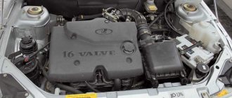
Before we begin to directly consider the issue of a malfunction associated with the tripping and blinking “CHECK” on the dashboard of a Gazelle Business car, it is worth considering the technical characteristics of the UMZ 4216 power unit:
| Name | Characteristic |
| Type | Row |
| Fuel | Petrol |
| Injection system | Injector |
| Volume | 2.9 liters (2890 cm3) |
| Power | 123 horsepower |
| Number of cylinders | 4 |
| Cylinder diameter | 100 mm |
| Consumption | 11 liters per 100 km |
| Cooling system | Liquid, forced |
| Econorm | Euro-3 |
Reasons if the engine stalls and the check light blinks
What are the specific circumstances of the origin of the result and how to respond independently.
Device and Specifications
Before we move on specifically to the consideration of the circumstances under which the engine fails, and in addition to the methods of response, let’s look at the main characteristics of the power unit. As practice has shown, the power unit has high performance, and based on this, it is loved by many car enthusiasts.
Simple reliability and design made the engine widespread among owners of Gazelle cars. Let's look at the main characteristics of the power unit:
This type of engine was used on Gazelle Business and Next vehicles.
Circumstances of engine tripping
Any engine tends to break down. Thus, the UMZ 4216 E-3 is also susceptible to malfunctions.
There is one SKODA RAPID car for everyone
SKODA RAPID is a car that can safely be called unique. Why? The answer is obvious - it will suit absolutely everyone! The dynamic character of the model and precise, refined handling combined with an interesting and stylish design will not leave the younger generation indifferent.
Older drivers will appreciate the nobility of the “crystalline” design, which is partly reminiscent of the traditions of the best crystal manufactories in the Czech Republic and the cubist architecture so beloved by all residents of Prague.
Elimination methods
What do experienced mechanics do during diagnostics:
- Open the hood and connect the equipment to read the error due to which the check light is on.
- They find the error and use it to navigate where the problem area is.
- If it is a spark plug, then it is replaced, if it is wires, then they are soldered or also changed. High-voltage wires are removed from the engine compartment. Test them using a multimeter. Set the multimeter needle to resistance and check each wire with it.
- Check the pressure in the fuel system to determine the faulty cylinder.
- Change the air filter. Because it can also be the cause of tripling.
- Catalysts are changed.
In case of serious problems, the engine is put in for a major overhaul.
SKODA RAPID – any trip is a pleasure
Skoda Rapid is the most affordable car of the entire SKODA line presented in Russia, but it is equipped with the most modern options usually offered for cars of a higher class. The appearance of an expensive European car, the design of which has no random details, combined with convenience and functionality, will exceed all your wildest expectations. Everything is thought out - down to the smallest detail.
And it’s not just about the pleasure that you will get when going through a bunch of turns at high speed - although the SKODA RAPID will easily provide this for you. Many details that can make every trip as convenient and comfortable as possible - this is what SKODA cars are valued for in more than a hundred countries around the world.
In general, it can be called a “city dweller” of the compact class. At the same time, the Skoda Rapid is a family car; its spacious interior and spacious luggage compartment are perfect for traveling with the whole family. Fits almost everything and even more! And if there is still not enough space, the luggage rack can be easily removed and the second row seats can be folded down.
Under the hood there is also something to be impressed with. SKODA RAPID engines are the embodiment of all the engineering power of the Volkswagen automaker. Their cost-effectiveness and time-tested reliability guarantee you years of trouble-free operation under the most demanding schedules and in the most challenging road conditions.
A family car should be truly comfortable, not only in the first row, but also in the second. After all, in a real family everyone should be equally comfortable. SKODA RAPID fully meets these requirements, because it is a car in which everyone will find a convenient and comfortable place for themselves. Even on the longest trip.
What is engine tripping?
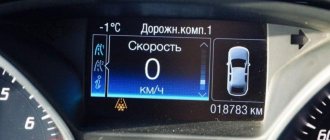
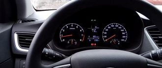
When the check light comes on, the power unit may operate unstably. The automatic transmission handle jerks. The engine stalls and has to be started again. These problems can arise due to various malfunctions with the internal parts of the engine.
A malfunction signal is sent to the engine electronic device unit or, simply, a computer. Where it is read by the brain and sent to the dashboard screen. The driver sees this signal and must take certain corrective actions.
Attention! When a check appears in a car with an eight-valve or sixteen-valve engine, you need to go to a service center to have the vehicle inspected. Further delay leads to discarding the unit and purchasing a new one.
If the engine still stalls when the check lamp comes on, this indicates the following engine malfunctions:
- possible damage to the catalyst;
- improper operation of valves or cylinders;
- fuel combustion occurs incorrectly;
- The ignition system is faulty.
These are only part of the reasons why the engine may stall. We will look at others in the next block. In any case, experienced mechanics do not recommend fixing the problem with the check on your own. Especially if the driver simply resets the check through the battery. Such a reset leads to such an outcome that all errors in the engine brain are reset to zero. And it is more difficult for experienced mechanics to find a breakdown in the engine.
Similar article Markers for setting the ignition on the 405 ZMZ timing engine
Gazelle Business Engine Umz 4216 Troit Reasons
4216 engine on and off in the Gazelle : prerequisites
Owners using the engine
UMP 4216 are having trouble starting the unit and here the Check Engine light is flashing. How to fix this failure and what is the reason for its occurrence.
Characteristics
Before we consider in detail the malfunctions associated with the operation and flashing of the “CHEK” on the dashboard of the Gazelle Business
", it is necessary to consider the technical characteristics of UMZ 4216:
Error and solutions
The prerequisites for the triple and flashing "Check" are almost identical for all units. The main reason is the incorrect formation of the air-fuel mixture.
, as this is called a breakdown in the ignition system. But it's okay.
Malfunction and solutions
The reasons for the occurrence of tripping and blinking “Check” are almost identical for all power units. The root cause may be improper formation of the air-fuel mixture or a breakdown in the ignition system. But, everything is in order.
Poor quality fuel
Low-quality gasoline, or in common parlance - “bad gas”, leads to the fuel supply elements becoming clogged, and the injection system itself forms a lean mixture. To diagnose and troubleshoot the problem, it is necessary to test the injectors. It is better to carry out this entire operation on a special stand. If it turns out that the elements are clogged, then we can say that the vehicle was operated on low-quality fuel.
Another reason could be a clogged fuel filter, which is recommended to be changed every 20,000 km. Also, it is worth examining the performance of the fuel pump, which may fail.
Ignition system
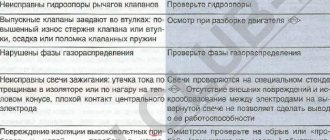
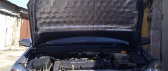
Breakdowns in the ignition system, namely malfunction of spark plugs, high-voltage wires and ignition coils, can lead to a tripping effect. So, you need to unscrew the spark plugs and inspect them for defects. Also, using a simple tester, measure the resistance of the high-voltage wires, which is 5 ohms.
Air supply
The formation of the air-fuel mixture is influenced by the state of the air supply. A clogged air filter element or throttle valve can cause a rich mixture, which can cause a tripping effect. To eliminate the malfunction, it is necessary to dismantle and inspect the elements.
If the air filter is clogged, it is recommended to replace it, but the throttle valve must be cleaned with a special product or liquid for cleaning carburetors.
Software problem
Repeatedly, the cause of the tripping and blinking “Check” is a malfunction of one of the sensors or accumulated errors inside the electronic engine control unit. So, it is necessary to diagnose the condition of the elements and replace damaged ones.
Allow the check engine light to go off on its own.
Wait for the “control” to turn off. The easiest way, because you practically don’t need to do anything. The computer system in most cars automatically rechecks for problems that may be causing the error light. If it is a minor problem, it will be automatically corrected and the "control" will be disabled. However, if the control continues to burn for three days, the above methods must be applied to restore it.
If this continues to happen despite the following reset procedures, you should take the vehicle to your nearest auto repair shop and have a professional mechanic diagnose it. Professional diagnostics use more sophisticated tools to identify specific problems.
REMEMBER: You can always contact our car service center, where your car will be happy to receive professional technical assistance. You can also schedule a scheduled inspection with us! Please check out our auto repair and diagnostic services.
ECU diagnostics
In order to understand which of the sensors or components affected the unstable operation of the engine, it is worth conducting a comprehensive diagnosis of the on-board computer. This requires an OBD II cable, a tablet and laptop, and software.
It is recommended to turn to professionals for help, who will quickly and efficiently perform diagnostic operations and fix the problem.
Deciphering error codes
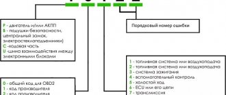
If the car owner nevertheless decides to fix the problem on his own, then he will need to decipher the error codes that will appear on the diagnostic computer screen. So, let's look at all the error codes and their interpretation for the UMZ 4216 engine:
| DTC | Description |
| P0105 | Incorrect air pressure sensor signal |
| P0107 | Low signal level from air pressure sensor |
| P0108 | High signal level from the air pressure sensor, |
| P0122 | Low signal level from throttle position sensor (1 track) |
| P0123 | High signal level from the throttle position sensor (1 track) |
| P0112 | Low signal level from air temperature sensor |
| P0113 | High signal level from the air temperature sensor |
| P0115 | Incorrect signal from the coolant temperature sensor |
| P0117 | Low signal level from the coolant temperature sensor |
| P0118 | High signal level from the coolant temperature sensor |
| P0130 | No activity of oxygen sensor No. 1 |
| P0131 | Low signal level from oxygen sensor No. 1 |
| P0132 | High signal level from oxygen sensor No. 1 |
| P0133 | Oxygen Sensor #1 - Slow Response |
| P0135 | Open circuit of oxygen sensor heater No. 1 |
| No. 1 oxygen sensor heater circuit short to ground | |
| Short to power in the oxygen sensor heater circuit No. 1 | |
| P0137 | Low signal level from oxygen sensor No. 2 |
| P0138 | High signal level from oxygen sensor No. 2 |
| P0141 | Open circuit of oxygen sensor heater No. 2 |
| Short to ground circuit of the heater of the oxygen sensor Lg "2 | |
| Short to power in the oxygen sensor heater circuit No. 2 | |
| P0201 | Broken injector of cylinder 1 |
| Ground fault in cylinder 1 injector | |
| Short circuit to power supply of injector 1 cylinder | |
| P0202 | Broken injector of cylinder 2 |
| Injector 2 cylinder short to ground | |
| Short circuit to power supply of injector 2 cylinders | |
| P0203 | Broken injector cylinder 3 |
| Injector 3 cylinder ground short | |
| Short circuit to power supply of injector 3 cylinders | |
| P0204 | Broken injector 4 cylinders |
| Injector 4 cylinder ground short | |
| Short circuit to power injector 4 cylinders | |
| P0217 | Engine temperature is above the maximum permissible |
| P0219 | Engine speed is above the maximum permissible |
| P0221 | Range limit of the difference between 1 and 2 tracks of TPS |
| P0222 | Low signal level from throttle position sensor (2 track) j |
| P0223 | High signal level from the throttle position sensor (2 track) j |
| Open circuit of the fuel relay | |
| P0230 | Fuel relay primary circuit short to ground |
| Fuel relay primary circuit short to power | |
| P0301 | Misfire in cylinder 1 |
| P0302 | Misfire in cylinder 2 |
| P0303 | Misfire in cylinder 3 |
| P0304 | Misfire in cylinder 4 |
| P0327 | Low signal level from knock sensor |
| P0339 | HF Sync Sensor Synchronization Error |
| P0335 | HF synchronization sensor break |
| P0341 | Phase sensor synchronization error |
| P0351 | Broken ignition coil 1 |
| P0352 | Broken ignition coil 2 |
| P0420 | Low efficiency of the exhaust catalyst |
| Open circuit of the canister purge valve | |
| P0443 | Short circuit to ground in the canister purge valve circuit |
| Short circuit to power in the canister purge valve circuit | |
| Cooling fan relay primary circuit open | |
| P0480 | Cooling fan relay primary circuit short to ground |
| Cooling fan relay primary circuit short to power | |
| P0501 | Broken vehicle speed sensor |
| • | Idle air control malfunction | |
| P0505 | Open circuit of the idle speed regulator |
| Idle air control circuit short to power | |
| P0563 | High on-board voltage |
| P0562 | Low on-board voltage |
| P0603 | Control unit EEPROM error |
| P0604 | Control unit external RAM error |
| P0605 | Error in the external ROM of the control unit (ROM1) |
| P0606 | Control unit initialization error |
| Open circuit of the CHECK ENGINE lamp | |
| P0650 | Short circuit to ground in the CHECK ENGINE lamp circuit |
| Short to power in the CHECK ENGINE lamp circuit | |
| P1107 | Low signal level from the barocorrection sensor |
| P1108 | High signal level from the barocorrection sensor |
| P1122 | Low signal level from the accelerator pedal position sensor (1 track) |
Gazelle UMZ 4216 - Trouble with the engine, look for the cause and find it
Show Control Panel
- Published: July 27, 2017
- Suddenly the engine started to stall, gradually misfires were observed every day, then they began to happen more and more often, the check light came on and the diagnostics showed misfires, then there were specific failures, the car began to twitch, I arrived at the parking lot and removed the wire, and in general it began to misfire constantly and barely start up.
Comments • 50
Salam brother whatsapp number can I ask something
so, ah, the check light is on!?
The misfire check is flashing. Here I just have the rough road sensor disabled.
UNDER THE HOOD I CAN SEE MY EYES SO MUCH. TRASH... LAYING FROM UNNECESSARY HOSES WIRES EH TY CONSTRUCTOR CRAP. Y.
Ay sau bol brother tomorrow for the reel
the author show me what the coil normally looks like, otherwise I don’t understand?
I have two, as in the photo video (like on the 406), in later models they began to install one coil.
I also only have it on gas and on petrol it only starts when it’s cold.
Why not immediately swap the coils? More precisely, rearrange the chips. and you don’t have to buy wires or spark plugs. DeL for a minute
Conclusion
Determining why the “Check Engine” blinks on a Gazelle Business with a UMZ 4216 engine and tripping appears is quite simple. To do this, it is worth carrying out a comprehensive diagnosis of the electronic control unit and deciphering the error codes. If this does not give anything, then the problem should be looked for in the formation of the air-fuel mixture or the ignition system.
Reviews. Auto News. Test drives
Main Menu
- Home
- P0105 OBD-II Error: Manifold Atmospheric Pressure (MAP) Sensor Malfunction
Using the Scanner
Using a scan tool is the easiest way to reset your check engine light. Here are 5 simple steps:
- Connect the scan tool to the OBD connector under the steering column. A laptop or tablet with the appropriate software is installed in the holder;
- Then turn on the car's ignition and turn on all the gadgets accordingly;
- On your mobile device, in the appropriate section, by clicking the “READ” button, look at the engine error codes. Using a pen, write down the codes in the order in which they were received. This will be needed for subsequent repairs.
- Let's remove the error code. Press the CANCEL button on the scanner. The Check Engine light will turn off if all trouble codes have cleared. Some scanning tools have many options, such as a still image that captures sensor readings. When you clear the codes, these readings are also reset. Note. Some scanners may have an automatic code clearing option and a "CLEAR" or "YES" button instead of a "CLEAR" button.
- Be sure to turn the ignition on before resetting codes.
P0105 OBD-II Error: Manifold Atmospheric Pressure (MAP) Sensor Malfunction
The MAP sensor is an integral part of the fuel injection system and provides information to the engine control unit (ECU) to ensure smooth engine operation and good fuel economy.
A MAP pressure sensor problem can have several causes:
- the output voltage of the sensor readings is outside the range of input parameters of the control unit;
- The most common problem is that the vacuum hose on the sensor may be broken, damaged or kinked;
- The sensor wiring may be bad, brittle, or have poor connections. It may also be located close to high voltage components, especially generators, ignition wires, etc.
- The sensor may get stuck in one position.
- problems in the fuel system or piston group. If the vehicle's fuel system has low pressure or a burnt valve, these faults prevent the MAP sensor from receiving the correct value.
Symptoms of the error
The "Check Engine" light on the dashboard comes on. Most often the car does not work normally. It idles unsteadily and accelerates randomly. This is all because the MAP sensor and throttle position sensor are not working in sync.
Diagnosis of DTC P0105
First the P0105 should be cleared from memory and rechecked to see if it returns. If the error reappears, a visual inspection must be performed to ensure that the vacuum lines and other hoses on the intake system are intact and in place. If everything is in place and there is no damage, you need to check the voltage at the sensor with the engine running to determine whether the voltage reading changes with engine speed.
How serious is the error?
DTC P0105 causes the engine to malfunction and requires immediate attention. It is extremely important that it is resolved as quickly as possible. The problem of the pressure sensor leads to excessive fuel consumption and unstable engine operation. Often, after resetting the error by the scanner, the car will work normally and the error will not return.
What needs to be repaired?
Vacuum lines and electrical connector and wiring. Disconnect/connect electrical connectors to ensure fresh contact. Check hoses for cracks and kinks, especially on older cars. If no problems are found, replace the MAP sensor.
Owners of Mercedes, Mitsubishi, and Opel cars often complain about the DTC p0105 error.
All errors GAZ 3110 (Volga), GAZ 31105 (Volga), VOLGA SIBER, GAZELLE (3302, 33023, 2705, 2217, 2752, 3221, 32213, 322132, BUSINESS, SOBOL, VALDAI), GAZELLE NEXT
What's the result?
Ease of use and accessibility allow adapters for the diagnostic connector to significantly simplify the procedure for checking a vehicle, reading and decoding ECU errors. It is also worth noting that the error can be quickly corrected without the need to disconnect the battery terminals, reset the critical error, and so on
Finally, we add that among the adapters available on the market there are devices that may not read errors recorded in the ABS control unit and in the Airbag modules. In other words, information for these items may not be available. For this reason, before purchasing an adapter, it is necessary to separately clarify the possibility of reading errors from the memory of the above and other engine control units from a particular device.
Because the “check” lights up on the dashboard. You can continue driving if “engine control” is turned on. What to check first.
The main signs by which you can identify problems with the DPKV crankshaft position sensor yourself. Causes of breakdowns, breakdowns, self-control.
For what reasons can the air-fuel mixture misfire in one or more cylinders? Diagnostics of faults, recommendations.
Computer diagnostics of a car engine and other components: why it is needed and what faults it detects. How to drive a car yourself.
The main reasons leading to exhaustion of the working mixture. Poor mixture in carburetor and injection internal combustion engines, as well as in gas engines. Diagnostics, repair.
The operating principle of the ECU, the design of the board and connectors. ECU data processing, CAN bus. Causes of malfunction of the engine control unit, repair or replacement of the control unit.
The Check Engine light comes on when your vehicle's computer detects a problem with the transmission. This may indicate a serious or minor complication, but ignoring it will certainly make the problem worse, leading to significant damage and costly repairs. You can avoid all problems if you know the reasons for the signal. However, sometimes it does not turn off even though the problem is resolved. In this case, it won’t hurt to learn how to fold a check.
Most drivers get annoyed if the control remains active even if the car's fault has been fixed. In this case, your car's computer is faulty and a little intervention is required to fix the problem.
GAS errors via OBDI protocol. Self-diagnosis.
012 — The unit’s self-diagnosis mode is turned on (short circuit of the L-line to ground). 013 - Low signal level of the mass air flow sensor (MAF). 014 - High signal level of the mass air flow sensor (MAF). 015 - Low signal level of the absolute air pressure sensor (DAP). 016 - High signal level of the absolute air pressure sensor (DAP). 017 — Low signal level of the air temperature sensor (DTV). 018 - High signal level of the air temperature sensor (DTV). 019 - Engine overheating (coolant temperature above 105°C). 021 - Low signal level of the coolant temperature sensor (DTOZH). 022 - High signal level of the coolant temperature sensor (DTOZH). 023 - Low signal level of the throttle position sensor (TPS). 024 - High signal level of the throttle position sensor (TPS). 025 - Low voltage level in the on-board network. 026 - High voltage level in the on-board network. 027 - Only for MIKAS: Malfunction of the DPKV or secondary ignition circuits. 027 - Only for AUTRON: Incorrect initial setting of the throttle position sensor (TPS). 028 - Only for MIKAS: Malfunction of the DPKV or secondary ignition circuits. 028 - Only for AUTRON: The crankshaft speed has exceeded the maximum. 029 - Only for MIKAS: Malfunction of the DPKV or secondary ignition circuits. 029 - Only for AUTRON: Incorrect connection of the crankshaft speed sensor. 031 — Low signal level of the (first) CO corrector. 032 — High signal level of the (first) CO corrector. 033 - Low signal level of the second CO corrector. 034 - High signal level of the second CO corrector. 035 - Low signal level of the main (first) lambda probe (oxygen sensor). 036 - High signal level of the main (first) lambda probe (oxygen sensor). 037 - Low signal level of the additional (second) lambda probe (oxygen sensor). 038 - High signal level of the additional (second) lambda probe (oxygen sensor). 041 - Malfunction of the (first) knock sensor (DS) circuit. 042 - Malfunction of the second knock sensor (DS) circuit. 043 - Low signal level of the recirculation valve position sensor. 044 - High signal level of the recirculation valve position sensor. 045 - Low signal level of the canister valve position sensor. 046 - High signal level of the canister valve position sensor. 047 - Low signal level of the power steering sensor (power steering). 048 - High signal level of the power steering sensor (power steering). 051 - Malfunction of 1 control unit. 052 - Malfunction of control unit 2. 053 - Malfunction of the crankshaft position sensor (CPS). 054 - Malfunction of the camshaft position sensor (DPRV). 055 - Malfunction of the vehicle speed sensor (VS). 056 - Short circuit of the ignition coil circuit of cylinders 1/4 (for AUTRON units). 057 - Short circuit of the ignition coil circuit of cylinders 2/3 (for AUTRON units). 058 — Open circuit of the crankshaft position sensor (for AUTRON units). 061 - Reset the control unit in working condition. 062 - Malfunction of the control unit's random access memory (RAM). 063 - Malfunction of the control unit's permanent memory (ROM). 064 - Malfunction when reading the flash RAM of the control unit (EEPROM). 065 - Malfunction when writing to the flash RAM of the control unit (EEPROM). 066 - Malfunction when reading the control unit identification code. 067 - Malfunction of 1 immobilizer. 068 - Malfunction of immobilizer 2. 069 - Malfunction of immobilizer 3. 071 - Low idle speed. 072 - High idle speed. 073 - Rich mixture signal from lambda probe 1 at maximum leanness. 074 - Lean mixture signal from lambda probe 1 at maximum enrichment. 075 - Rich mixture signal from lambda probe 2 at maximum leanness. 076 - Lean mixture signal from lambda probe 2 at maximum enrichment. 079 — Malfunction when adjusting the recirculation valve using the sensor. 081 — Maximum displacement of the ignition timing angle (IAF) by detonation in cylinder 1. 082 — Maximum displacement of the ignition timing angle (IAF) by detonation in cylinder 2. 083 — Maximum displacement of the ignition timing angle (IAF) by detonation in cylinder 3. 084 — Maximum displacement of the ignition timing angle (IAF) by detonation in cylinder 4. 085 - Maximum displacement of the ignition timing angle (IAF) by detonation in cylinder 5. 086 - Maximum displacement of the ignition timing angle (IAF) by detonation in cylinder 6. 087 - Maximum displacement ignition timing (IAF) for detonation in cylinder 7. 088 - Maximum displacement of the ignition timing (IAF) for detonation in cylinder 8. 091 - Short circuit to the on-board network in ignition circuit 1. 092 - Short circuit to the on-board network in ignition circuit 2. 093 - Short circuit to the on-board network in ignition circuit 3. 094 - Short circuit to the on-board network in ignition circuit 4. 095 - Short circuit to the on-board network in ignition circuit 5. 096 - Short circuit to the on-board network in ignition circuit 6. 097 - Short circuit to the on-board network in ignition circuit 7. 098 - Short circuit to the on-board network in circuit 8 of the ignition. 099 - Malfunction of the high voltage driver. 131 - Short circuit to the circuit board of injector 1. 132 - Open circuit or short to ground of the injector circuit 1. 133 - Short circuit to ground of the injector circuit 1. 134 - Short circuit to the circuit board of the injector 2 135 - Open circuit or short circuit to ground of the injector circuit 2. 136 — Short circuit to ground of the injector circuit 2. 137 — Short circuit to the electrical system of the injector circuit 3. 138 — Open circuit or short circuit to ground of the injector circuit 3. 139 — Short circuit to ground of the injector circuit 3. 141 — Short circuit to the electrical system of the circuit injector 4. 142 - Open circuit or short to ground in the injector 4 circuit. 143 - Short circuit to ground in the injector 4 circuit. 144 - Short circuit to the on-board network of the injector 5 145 - Open circuit or short to ground in the injector 5 circuit. 146 - Short circuit to ground of injector circuit 5. 147 - Short circuit to ground circuit of injector circuit 6. 148 - Open circuit or short circuit to ground of injector circuit 6. 149 - Short circuit to ground of injector circuit 6. 151 - Short circuit to ground circuit of injector circuit 7. 152 - Open circuit or short circuit to ground of the injector circuit 7. 153 - Short circuit to ground of the injector circuit 7. 154 - Short circuit to the on-board network of the injector circuit 8. 155 - Open circuit or short circuit to ground of the injector circuit 8. 156 - Short circuit to ground of the injector circuit 8. 157 - Short circuit to the on-board network of the starting injector circuit. 158 - Open or short to ground in the starting injector circuit. 159 - Short circuit to ground in the starting injector circuit. 161 - Short circuit to the on-board network of control circuit 1 of the additional air regulator (RDV or IAC). 162 - Open circuit or short to ground in control circuit 1 of the additional air regulator (RDV or IAC). 163 - Short circuit to ground in control circuit 1 of the additional air regulator (RDV or IAC). 164 - Short circuit to the on-board network of control circuit 2 of the additional air regulator (RDV or IAC). 165 - Open circuit or short to ground in control circuit 2 of the additional air regulator (RDV or IAC). 166 - Short circuit to ground in control circuit 2 of the additional air regulator (RDV or IAC). 167 - Short circuit to the on-board network of the electric fuel pump relay circuit. 168 — Open circuit or short to ground in the electric fuel pump relay circuit. 169 - Short circuit to ground in the electric fuel pump relay circuit. 171 - Short circuit to the on-board network of the recirculation valve circuit. 172 - Open circuit or short to ground in the recirculation valve circuit. 173 - Short circuit to ground in the recirculation valve circuit. 174 - Short circuit to the on-board network of the canister valve circuit. 175 - Open circuit or short to ground in the canister valve circuit. 176 - Short circuit to ground in the canister valve circuit. 177 — Short circuit to the main relay circuit on-board. 178 — Open circuit or short to ground in the main relay circuit. 179 - Short circuit to ground in the main relay circuit. 181 - Short circuit to the on-board network of the malfunction lamp circuit (Check Engine). 182 - Open circuit or short to ground in the fault lamp circuit (Check Engine). 183 - Short circuit to ground in the fault lamp circuit (Check Engine). 184 - Short circuit to the tachometer circuit. 185 - Open or short to ground tachometer circuit. 186 - Short circuit to ground in the tachometer circuit. 187 - Short circuit to the on-board network of the fuel flow meter circuit. 188 — Open or short to ground in the fuel flow meter circuit. 189 - Short circuit to ground in the fuel flow meter circuit. 191 - Short circuit to the on-board network of the air conditioner relay circuit. 192 - Open or short to ground in the air conditioner relay circuit. 193 - Short circuit to ground in the air conditioning relay circuit. 194 — Short circuit to the on-board network of the cooling fan relay circuit. 195 — Open or short to ground in the cooling fan relay circuit. 196 - Short circuit to ground in the cooling fan relay circuit. 197 - Short circuit to the on-board network of the EPHH valve circuit. 198 — Open circuit or short to ground in the EPH valve circuit. 199 — Short circuit to ground in the EPH valve circuit. 231 - Open circuit or short to ground in ignition circuit 1. 232 - Open circuit or short to ground in ignition circuit 2. 233 - Open circuit or short to ground in ignition circuit 3. 234 - Open circuit or short to ground in ignition circuit 4. 235 - Open circuit or short to ground in ignition circuit 5. 236 - Open circuit or short to ground in ignition circuit 6. 237 - Open circuit or short to ground in ignition circuit 7. 238 - Open circuit or short to ground in ignition circuit 8. 241 - Short circuit to ground in ignition circuit 1. 242 - Short circuit to ground in ignition circuit 2. 243 - Short circuit to ground in ignition circuit 3. 244 - Short circuit to ground in ignition circuit 4. 245 - Short circuit to ground in ignition circuit 5. 246 - Short circuit to ground in ignition circuit 6. 247 - Short circuit to ground in ignition circuit 7. 248 - Short circuit to ground in ignition circuit 8. 251 — Short circuit to the on-board network of the mass air flow sensor burning circuit. 252 — Open or short to ground in the burning circuit of the mass air flow sensor. 253 - Short circuit to ground in the burning circuit of the mass air flow sensor.