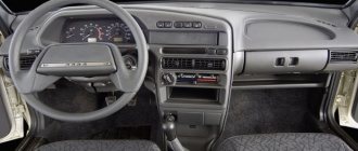
It is the front suspension that most often “takes the blows of fate”, being the most loaded component of the car’s chassis. That is why care and timely inspection of its main components, their repair and replacement will be the key to successful driving of the VAZ 2107.
The entire front suspension of the “classic” is more reliable than subsequent front-wheel drive modifications of the VAZ, since a car with rear-wheel drive has fewer parts in the front suspension, its design is more “economical”.
The design of the front suspension has important components, without which a smooth ride of the car is impossible.
Let us describe the design of the front suspension on the VAZ 2107:
- double wishbone suspension, there are upper and lower arms that exist independently; the upper one is secured through the mudguard strut with a long bolt, the lower one is bolted to the suspension cross member, which, in turn, is connected to the front side members.
- silent - blocks, or rubber-metal hinges of quiet running. They are needed for the levers to turn. When worn out, replacement is required.
- ball joints, or simply “ball” joints - the wheel hub is ultimately installed to them through a steering knuckle system with a pin.
- The shock absorption device includes a spring installed in the cups and a hydraulic shock absorber installed inside the spring.
- The list of main devices is completed by a lateral stability bar (stabilizer).
The structure and most important parts of the VAZ 2107 suspension:
5 — knuckle axle; 9 — ball pin of the upper support; 10 — steering knuckle; 13, 36 — upper and lower arms; 17 — support glass; 18 — shock absorber mounting pads; 21 — upper spring support cup; 22 — axis of the upper arm; 29 — bracket for fastening the cross member to the spar; 30 — cross member of the front suspension; 33 — stabilizer bar; 34 — body spar; 37 — bolts for securing the lower arm axis; 40 — shock absorber;
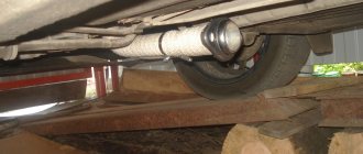
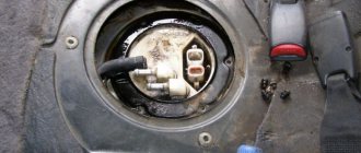
This is what the pendant looks like from below. All structural elements are clearly visible (levers, spring, shock absorber, stability bar, balls, etc.).
What can be determined when inspecting the suspension?
- The state of wear, crumbling, dryness of all rubber parts;
- It is determined how dry the shock absorber is and whether there is any oil leakage from it, as well as evaluate its performance. The test scheme is simple: you need to sharply press on the surface of the car's wing and remove the load, that is, “release sharply”. A working shock absorber returns the wing up in one pass, without additional vibration.
- The integrity of all coils of springs on the right and left sides;
- The gap in the ball joints is determined.
Preparing and disassembling the unit
The front rolling bearings are roller, cone type, consisting of two parts: external and internal. Good quality products are sold complete with the required amount of lubricant and two clamping nuts. The nuts differ in their thread, on one it is left-handed, on the other - right-handed, the first will fit the axis of the right axle, the second - to the left.
The manufacturer does not know which wheel will be replaced, so he completes the product with both nuts. Additionally, you need to purchase an oil seal, which is located at the rear of the hub and does not allow grease to leak out. You can carry out the work on a level surface, securing the car with the hand brake so that it does not roll away.
Before lifting the car with a jack, you need to pull out the metal boot covering the hub nut and loosen the latter with a 27 mm wrench. Then the wheel bolts are loosened, the car is jacked up and the wheel is removed. The next step is to remove the brake caliper, which is attached to the axle with 2 bolts; they need to be unscrewed, the part removed and moved to the side.
It is recommended to first remove the brake pads from the caliper, then it will be easier to put it back.
Now you can completely unscrew the nut, pull out the washer and remove the hub from the axle axle by hand. After this, you need to remove the old grease from all parts; it contains metal shavings.
Replacing ball joints
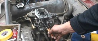
The work scheme (like all others) begins with cleaning the parts from dried dirt. You need to make it a rule to clean all the elements at the bottom of the machine before starting diagnostics and repairs. The most convenient way to do this is to first use a stream of water from the nozzle of a portable car wash, and then dry it with compressed air.
To replace the ball joints, first remove the wheels of the VAZ 2107.
The jack for loading the lower part of the suspension rests on the lower arm, simulating a “load” on the suspension.
- Unscrew the ball pin nut (for example, the top one).
- A special pressing tool is used to separate the steering knuckle and the support pin;
- Unscrew the ball joint and remove it in its protective case.
- A new support is installed and assembly occurs in the reverse order.
The lower support is also replaced. After this, the car is jacked up on the other side and the ball joints on the other side of the suspension are replaced.
After this, it is necessary to adjust the wheel alignment; this must be done at a service station on a special stand.
Let us recall that the silent block is a connecting element in the suspension of the VAZ 2107, and any other “classic”, which has an elastic liner made of polyurethane or rubber in order to soften the shocks of the suspension and vibrations. These parts take on large shock loads.
The figure shows the mounting diagram for the silent block of the lower arm.
Because of this, silent blocks are susceptible to wear, as a result of which the alignment is disrupted. It is advisable to change silent blocks every 50-100 thousand km. Mileage.
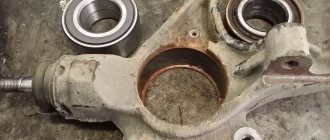
Steering knuckle repair
Repair of the steering knuckle is possible with minor wear or minor damage. As a rule, if a unit is seriously damaged after an accident, car enthusiasts simply replace it with a new one.
Repair work is only possible after the steering knuckle has been completely removed from the vehicle. The repair schedule looks like this:
- Clean the surfaces of the fist from dirt and dust, wipe it with a clean cloth, and blow with compressed air.
- Clean the grooves for the retaining rings.
- Inspect the steering knuckle after dismantling for signs of deformation and wear.
- Install a new retaining ring and press the new bearing in until it stops.
- If it is necessary to replace the trunnion, replace it. If the axle and kingpin are severely worn, it is recommended to replace the steering knuckle assembly.
Repairing the steering knuckle involves replacing the retaining rings and bearing. In case of extensive damage, only replacement is recommended.
If the pin wears out and the threads are “eaten”, there is only one way out - replacement
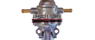
Replacing shock absorbers
The shock absorber is a non-separable paired part. That is, if one of them fails, then both change.
In order to replace the shock absorber, you need to carry out the following steps:
- Unscrew the fastening nut on the rod;
- Remove the washers along with the upper cushion made of rubber;
- We unscrew the bracket with which the shock absorber is connected to the lower arm;
- The broken shock absorber can be removed through the slot in the lever housing;
- The bracket is removed from the shock absorber and a new shock absorber is installed in the reverse order.
↑ Control system diagnostic sequence
If there are any malfunctions in the steering (knocks, increased free play of the steering wheel or, conversely, its tight rotation, etc.), inspect the steering parts. Carry out the inspection on an overpass or in an inspection ditch in the following order.
Clean the steering gear parts and steering gear housing from contamination. Set the wheels to a position suitable for driving in a straight line.
When turning the steering wheel in both directions, make sure that:
- free play of the steering wheel does not exceed 5° (when measured along the wheel rim no more than 18–20 mm);
- there are no knocks in the hinges, joints and steering mechanism;
- the steering gear housing and the pendulum arm bracket are securely fastened (tighten the threaded connections if necessary);
- there is no free play in the ball joints of the rod and in the bracket of the pendulum arm, and the worm shaft does not move in the axial direction;
- the steering wheel turning force (when installing the front wheels on a smooth plate) does not exceed 196 N (20 kgf).
When turning the side link adjusting couplings, make sure that their clamps are securely tightened.
Check the condition of the ball joints and protective caps as follows.
Product added to bookmarks!
- Description
- Reviews
APPLICABILITY: VAZ 2101, 2102, 2103, 2104, 2105, 2106, 2107.
DIMENSIONS: shortened by 30 mm
.
MATERIAL: forged cast iron.
INSTALLATION: shortened bipods are designed to increase the maximum turning of the front wheels. It may be necessary to modify or replace the steering “strains” (depending on the front suspension arms you have installed).
ADVANTAGES:
suitable for those who want to increase their wheel alignment, but are not ready for major changes. When using these steering bipods, you can drive a car every day (there will be no increased wear of tires and instability in control during normal driving). Also, this is an excellent option for winter competitions: circuit racing or drifting.
ADDITIONAL INFORMATION:
The Ackerman angle relative to the standard bipod has been changed.
FRONT SUSPENSION VAZ 2107: DEVICE, FAULTS AND MODERNIZATION
The most loaded element of the VAZ 2107 car is the front suspension. Indeed, it takes on almost all mechanical loads that arise during movement. For this reason, it is important to pay careful attention to this unit, carry out timely repairs and modify it, whenever possible installing more durable and functional elements.
PURPOSE AND DEVICE OF THE FRONT SUSPENSION
Suspension is usually called a system of mechanisms that provide an elastic connection between the chassis and wheels of a car. The main purpose of the unit is to reduce the intensity of vibrations, shocks and jolts that occur during movement. The vehicle constantly experiences dynamic loads, especially when traveling on poor quality roads and when transporting cargo, i.e. in extreme conditions.
It is at the front that the suspension most often takes impacts and shocks. It is rightfully the most loaded part of the entire car. On the “seven” the front suspension is made better and more reliable than the rear - the manufacturer, of course, took into account the high load on the unit, but this is not the only reason. On rear-wheel drive cars, the front suspension has fewer parts than the rear, so its design is less expensive.
The front suspension diagram of the VAZ 2107 includes important parts, without which the smooth movement of the car would be impossible.
- Stabilizer or lateral stability beam.
When cornering, the anti-roll bar redistributes the load on the wheels and keeps the car parallel to the road.
- Double wishbone suspension is the main chassis unit at the front, consisting of an upper and lower independent link. One of them is fixed with a long bolt through the mudguard strut, the other is bolted to the suspension cross member.
The upper arm (item 1) is attached to the mudguard strut, and the lower arm is attached to the suspension cross member
- Ball joints are connected to the wheel hubs through axle-mounted knuckle systems.
- Wheel hubs.
- Silent blocks or bushings - designed for free movement of levers. They have an elastic polyurethane (rubber) liner that significantly softens the shock of the suspension.
The silent block serves to soften impacts transmitted by front suspension elements
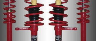
- Shock absorption system - includes springs, cups, hydraulic shock absorbers. On VAZ 2107 models of the last years of production and on tuned “sevens”, struts are used.
FRONT BEAM
The task of the front beam is to stabilize the car when cornering. As you know, during a maneuver a centrifugal force arises, which can cause the car to roll over. To prevent this from happening, the designers came up with a transverse stability beam.
The main purpose of the part is to twist the opposite wheels of the VAZ 2107 using a torsion elastic element. The stabilizer is attached using clamps and rotating rubber bushings directly to the body. The rod is connected to the suspension elements through double levers and shock absorber struts or, as they are also called, bones.
LEVERS
The front levers are the guiding components of the VAZ 2107 chassis. They provide a flexible connection and transmission of vibrations to the body.
The levers are directly connected to the wheels and body of the car. It is customary to distinguish between both suspension arms of the “seven”, since their replacement and repair are carried out in different ways:
- the upper arms are bolted, making them easier to remove;
- The lower arms are screwed to a cross member connected to the spar; they are also connected to a ball joint and a spring - replacing them is somewhat more difficult.
The upper and lower arms are directly connected to the wheels and body of the car
FRONT SHOCK ABSORBER STRUT
The owners of the VAZ 2107 learned about the existence of racks when the VAZ 2108 model appeared. From that time on, the manufacturer began to gradually install new mechanisms on the “sevens”. In addition, the racks were chosen by specialists modernizing a classic car.
The strut is part of the shock-absorbing system, the task of which is to dampen vertical vibrations of the body, taking on some of the impacts. The stability of the car on the road depends on the technical condition of the rack.
A few words about the hub
Why am I talking about the hub, although we are talking about the axle? Because some beginners cannot understand the differences between these two mechanisms. We need to clarify a little on this issue. Without a hub, a car will not be able to receive torque and transmit it to the wheel so that the vehicle can move. The wheel rim is also attached to it. In general, it is a blank of metal. I would like to dwell in more detail on its constituent elements:
- A housing in which studs of various numbers, diameters and lengths are installed. They depend on the weight and size of the machine. Due to the heavy load on the road surface, which is transmitted to the suspension through the wheel, the body of the part consists of high-strength steel with thickened walls.
- The bearing is inside the housing, completely reducing friction when the wheel rotates.
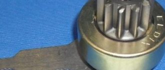
- Splines installed in the inside of the bearing. The CV joint elements pass through the hole and transmit torque from the engine. This is how the wheels are set in motion.
- Fixing and fastening devices for cables and wires that lead to the on-board system (if various pressure sensors and ABS are present).