Each cylinder must receive a spark at a strictly defined time. On old engines, a switch was used for this - a distributor. It supplied a high-voltage pulse from a single ignition coil to the desired spark plug. Since the operating principle of the unit is mechanical (an ordinary slider with contacts), the reliability left much to be desired.
Modern engines use an electronic ignition module. The injector synchronizes the timing of fuel injection with the supply of a spark. The engine runs more smoothly, fuel consumption decreases, and efficiency increases. There is also the other side of the coin. If any owner of a Zhiguli or Moskvich could repair the mechanical ignition system with his own hands, the ignition module of the new model requires knowledge of the circuit and certain skills.
Of course, you can contact the specialized service for any reason. But then the cost of owning an iron horse will increase. A basic check of the ignition module takes a few minutes of your time; all you need is a tester. Most often, to repair an electronic module, you just need to ring the wires and understand the principle of operation of the device.
We disassemble the design of the ignition module of a modern injector
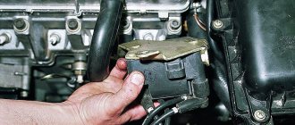
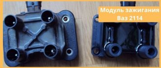
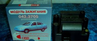
As an example, consider a similar device used on injection VAZ cars. The module operates according to the good old principle: 12 volt power is supplied to the input, and a high voltage is generated at the output contacts for sparking.
The control is electronic, but the operating principles differ from a simple distributorless ignition system:
- All components are located in one housing. On the one hand, this is convenient - fewer wires and contacts - lower probability of breakdown. On the other hand, if the ignition module burns out, it must be repaired; simply replacing the failed element will not work.
- The device is compact and can be conveniently placed in the engine compartment.
- The ignition module is powered at low voltage, which increases the reliability of the device.
- The cost of the finished device is low.
- This ignition module has two coils. This contributes to the survivability of the device - each transformer is loaded twice as much.
The secret of the module’s operation is as follows: it uses not four, but two coils for 4 cylinders. Masters of the old school call this device a two-spark bobbin. Alternating connection of each coil produces two sparks: working and idle. Due to proper distribution among the spark plugs, the idle spark is ignited at the moment when there is no air-fuel mixture in the corresponding cylinder.
As a result, we get savings on coils (as a result - a reduction in cost), and stable performance of the motor.
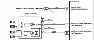
The signal for sparking is given by the switch (acting as an electronic distributor). Before checking the ignition module, you need to make sure that control pulses are coming to the contact blocks from the switch.
This block is responsible for the so-called ignition advance, that is, it generates a signal at the right moment. The control pulse about the position of the crankshaft is issued by the Hall sensor, which also synchronizes the operation of the entire system.
Checking for errors
VAZ 2114 engine mounts signs of malfunction
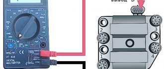
Checking the ignition device for malfunctions always concerns the location of the wires on the ignition module of the VAZ 2114. For simple diagnostics, we simply measure the resistance between the wires of the first and fourth cylinders and the second and third cylinders with a multimeter. If the indicator is 5.5 kOhm (switch the multimeter to ohmmeter mode!), then everything is in order. There are also other checks:
- The first thing to check is the wiring block; it is better to disconnect it and check it with a multimeter in voltmeter mode: we attach the multimeter probe to pin A, and throw the other one onto the ground of the sliders. We start and look at the voltmeter values: excellent. If the voltage fluctuates around 12 V. If there is no voltage, check the ignition coil fuse, it may blow, as well as the correct connection of all contacts. By the way, about that. Another way of checking can indicate that the circuit of contacts is closed incorrectly: by connecting a tester to both contacts - A and B - connect a multimeter to it; if it blinks, then the circuit is in perfect order.
- It’s worth checking all the high-voltage elements (with the same multimeter in ohmmeter mode); if they are installed incorrectly, the ignition coil will burn out.
- To understand whether the ignition module behaves correctly, move the wire block, you can knock on it. The contact should not disappear, if the engine responds to your movements, the contact is unclear. It can break at any moment.
Symptoms of an ignition coil malfunction are often displayed by the system during basic diagnostics in a service center (or in a garage environment via a connected laptop with a special program) in the form of errors:
- P0351 – break in the winding of wires of cylinders 1-4
- P0352 – break in the wire winding of cylinders 2-3
- P3000 (P3001 P3002 P3003 P3004) – the ignition does not work.
All these errors are motivation for a deeper diagnosis of the situation, on which the decision will depend: replace the module with a new one, or repair it. Also, these errors may indicate a possible malfunction of one of the spark plugs or an explosive contact.
Ignition module: connection diagram
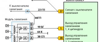
To diagnose and repair breakdowns, you need to understand which wires come from where and what they are responsible for. If the engine fails, is it the spark plugs or the switch? Again, let's look at the circuit using the example of the VAZ 2114, 2115 ignition modules.
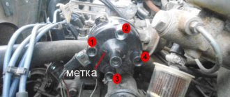
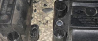
On the body of the device there is a block with 4 contacts A,B,C,D (of course, modules from other cars have different markings, but the principle remains the same). Ground contact is the default; the design of the car allows all electronic modules to be connected by a negative bus. Power is supplied from a 12 volt bus, “RUN ON”, that is, it works after turning the ignition key (don’t forget about this when testing with a tester). The system is powered through a fuse, often shared with some other devices. Diagnosis of the ignition module begins with checking the fusible element.
Two main contacts: output to 1-4 candles, and 2-3 candles. It is to them that the control signal comes from the switch. The connections are straight, dialed through the contacts of the pads. The pad itself is quite flimsy and must be handled with care. The same cannot be said about power outputs for high-voltage wires.
Important! For safety reasons, it is recommended to disconnect the battery terminals before removing high-voltage wires. At least at this moment the ignition key should be in the "off" mode.
These contacts are directly connected to the working terminals of the spark plugs. Often the problem lies in high-voltage wires. It is enough to replace them, and repair of the ignition module will not be required.
By running your hand along these wires away from the spark plugs, you can easily determine where the ignition module is located. Of course, in the engine compartment, at a short distance from the cylinder block (extra length of the high-voltage cable reduces the reliability of the system). As a rule, removing the ignition module for diagnostics, repair or replacement does not require dismantling other components.
Repair
So, for the VAZ 2110 the most common problem is the disappearance of voltage on cylinders 2 and 3. After some time, the engine starts working normally again if you press the rear plate of the module.
You should not put up with such a situation; it is better to immediately check the functionality of the unit, restore or replace it completely.
Removing the module
The procedure is quite simple.
- Disconnect the negative cable from the battery.
- Remove the plastic cover that covers the motor.
- Remove the wires from the spark plugs.
- Disconnect the wires from the ignition module. Their numbering is indicated on special white rings. And the cylinder number is indicated on the ignition module housing.
- Disconnect the connector from the ignition module.
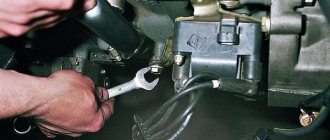
- Using a 10mm socket, unscrew the three nuts that hold the block we are looking for.
- Carefully remove it, after which you can begin further work.
Now let's move directly to working with the module:
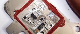
- Open the aluminum plate on the ignition module. A flathead screwdriver is useful for this.
- Inside you will find a small printed circuit board with electronic components. It is covered with a transparent layer of silicone, which will have to be removed.
- There are also wires that connect the board to the connector contacts. They are made of aluminum, so they can tear quickly.
- Tear off all the wires from the contacts, don’t be afraid. Others will be installed in their place. By the way, experts recommend using stranded wires used in computer mice.
- The ignition module circuit includes two switches and two powerful transresistors. If you decide to change these elements, you need to know that the switches are manufactured by SGS-THOMSON (model L497D1), and the transistors are of the BU931 type.
- The contacts are made of aluminum, so you will need a special flux to work with this metal.
- We solder the wiring to the board. It is more difficult to solder to the transistor collectors, since they are covered with a special material, the soldering of which is problematic. Therefore, try to hide the top coating from the element as carefully as possible. To prevent the soldering iron from transferring all the heat to the plate, place it on the stove and heat it to 180 degrees Celsius.
- Solder the wires to the contacts on the module so that they are as short as possible.
- Cover the areas where you soldered with varnish. Regular nail polish borrowed from your wife will do.
- Check if the ignition module is working.
- If everything is fine, coat the inner surface with a special autosealant, then reassemble in the reverse order.
- Upon completion of assembly, the wiring should be positioned fairly freely. Make sure that they are not compressed inside the box and that the integrity of the connections is not broken.
Carrying out a similar repair of the ignition module on a VAZ 2110 with your own hands will not be difficult.
But be careful, act carefully and consistently
Pay special attention to the soldering process
But keep in mind that we have addressed the problem of bad contacts. She is not the only one for the “ten”. You may need to pinout the ignition module on the VAZ 2110. For this, it is better to contact specialists.
If the cause of the malfunction lies elsewhere, then there is a high probability that it is better to simply replace the VAZ 2110 8-valve ignition module with a new one. The search may drag on without yielding results. Replacing the element will completely solve the current problem.
Possible causes of failure
The weak point of the ignition coils and modules is the secondary winding, which generates a high voltage pulse. A coil break or breakdown may occur in it. The following factors lead to this phenomenon:
- use of low-quality or unsuitable candles;
- operation with non-functioning high voltage wires;
- frequent attempts to check the spark.
The high-voltage pulse arising in the secondary winding must be realized (spent). If this does not happen (if the integrity of a high voltage wire is broken, for example), a high-energy electrical pulse seeks an outlet. He will find it, with a high degree of probability, in the thin secondary winding.
Often, a module malfunction occurs when the integrity of poor-quality factory soldering of wires going to the switch elements is violated. This happens from vibration. Also, the cause of non-working coils can be a banal contact failure in the incoming connector. Another factor leading to a malfunction of the ignition unit is often moisture that gets on the device during washing or driving in unusual conditions.
Signs of a malfunctioning ignition module
The list is relevant only if the other systems (spark plugs, injectors, crankshaft position sensor, cylinder compression, fuel system) are in good working order and operate according to the established parameters. The symptom of a faulty spark plug may not differ from a banal loss of contact between the ignition module and the high-voltage cable.
- Troubles the engine. In fact, there are many reasons, but the main culprit is our module. Moreover, this could be a contact phenomenon, or a breakdown of the radio element. A clear sign of coil failure is that failures occur in two cylinders simultaneously. That is, candles either Nos. 1 and 4 or Nos. 2 and 3 “do not burn.”
- The engine thrust has noticeably decreased. The car does not hesitate, it runs smoothly, but acceleration uphill or under load occurs lazily.
- During sharp acceleration, a kind of failure of thrust occurs in the engine. It's as if the fuel pump is not performing enough. If the gas tank is in order, look for the cause in the ignition module.
- At idle the speed fluctuates (of course, with the IAC running).
And of course, the “check engine” alarm. If the fault is detected by the ECU module, this is good for diagnosis. You can read OBD errors in any available way:
- using electronic odometer codes (if such an option is available);
- using the on-board computer, if it has a decoding function;
- any diagnostic scanner, for example, ELM327 paired with a smartphone.
If you recognize error codes associated with misfires specifically in a pair of spark plugs, the most likely cause is a faulty ignition module.
Replacement
Replacement is quite simple and effortless. To replace, you will need a ratchet with an extension and a 10mm socket.
Replacement process
- We remove the negative mark from the battery, since the work is carried out on the electrical equipment of the car. This will avoid an unintentional short circuit in the vehicle's network.
- We remove the high-voltage wires from the MZ and the power connector.
- We unscrew the nuts securing the MZ and dismantle it.
- Installation is carried out in reverse order.
Pay attention to the order in which the wires are connected. Do not confuse them, otherwise the car engine will not start. Cylinder numbering starts from the timing mechanism from left to right. Connect the wires as it is written on the Ministry of Health.
How to check the ignition module yourself?
Let's say you have clearly determined that the engine is malfunctioning (maybe another malfunction) due to the ignition module. You know where it is located, the pinout of the input block is known. To decide whether to repair the module or replace it with a new one (this is your cost), we will test it at least with a multimeter.
- The easiest way is to replace the unit with a known good one. This is only possible if you have a good friend with a similar car. With such a check, the so-called “support group” - cables, electronic switch.
- Performance of the contact group. While the motor is running, press on the plugs of the high-voltage wires (Caution!) and the control block. If the nature of the motor’s operation has changed (it does not oscillate, the speed has become stable), check the condition of the contacts.
- We measure the resistance at the coil contacts. Secondary windings are guaranteed to be tested. Between the output contacts of 1.4 and 2.3 candles, the resistance should be the same and within 5 Ohms.
- We examine the disassembled module. Of course, you need to have basic skills in electrical engineering (the level is somewhat higher than “screwing in a light bulb in a hallway”). Broken wires or burnt contacts are immediately visible, and the serviceability of transistors can be checked with a multimeter. The primary winding of the coils becomes accessible.
If the parts are replaceable, we carry out repairs. Wiring and contacts are restored simply.
Version of the module on the 8-valve VAZ-2110
The top ten was equipped with two 8-valve engines of different sizes - 1.5 (2111) and 1.6 liters (21114). The ignition modules for these engines are different.
- The one and a half liter engine has a module with article number 2112-3705010,
- and the 1600 cc is equipped with module 2111-3705010.