Ignition of gasoline in the cylinders of an internal combustion engine occurs using a spark generated by the ignition system. The ignition module is the main element of the system, creating a spark on the spark plugs using high voltage. Each car manufacturer develops and produces its own original module, but the principle of its operation is the same for all devices. During operation, deviation from the specified parameters or breakdown of the ignition module negatively affects engine operation until the power unit fails.
Purpose and principle of operation
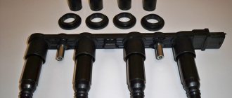
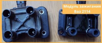
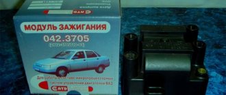
Ignition module VAZ 2110
The ignition module of a modern car performs the function of generating high voltage to produce a spark at the spark plugs. It consists of two coils with a closed magnetic circuit and a two-channel switch. Sometimes the switch is made as a separate device, but in most cases it is combined with an electronic control unit for the engine. Externally, the modules differ in the number of wires in the connection connector: a module with a switch has 4 wires, and paired coils have 3.
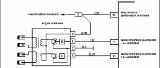
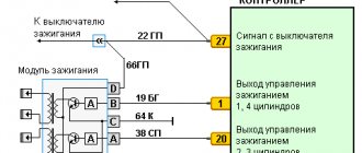
The ignition module is controlled by the ECU, which supplies constant voltage in the form of low-voltage control signals to the windings of its coils at the right moment. The end of the signal is the beginning of the spark. Thanks to magnetic induction, at the moment of application, a high voltage is generated, creating a spark at the spark plug. The device is located in the engine compartment and can be easily identified by the high-voltage wires leading to the spark plugs.
Repair
Ignition module VAZ 2107
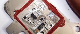
The design of the ignition module is quite complex: it includes one or more coils, a board, contacts and wires. Of all the above elements, only contact connections can be repaired; in some cases, replacement of parts (transistors, coils) is possible.
The module is dismantled and opened for repair purposes. For this you will need:
- Socket wrenches with heads 1, 13 and 17.
- Hexagon 5.
- Screwdriver.
- Soldering iron.
- Flux for aluminum.
- Stranded wire.
- Nail polish.
Opening the ignition module
Repair of the ignition module is carried out in the following order:
- On the removed device, open the case by prying it off with a screwdriver.
- Remove the silicone film covering the board.
- All aluminum is removed from the explosive contacts.
- On the board, new wires are soldered in place of all the dismantled old ones. To do this, the surface of the collector is cleaned of deposits, after which the board is heated to 180 o C (a characteristic smell will indicate when the desired temperature has been reached). During the soldering process, the ends of the wires are connected to the module.
- At the end of the operation, all contacts, the board and the module are covered with nail polish.
- The device is assembled in the reverse order, installed on the car and the engine is started. In case of normal operation, the ignition module is sealed tightly with sealant, while the wires are tucked inside the cavity so that they are not pinched at the edges by the plate.
If the device does not work, then a breakdown inside the module should be looked for more carefully. The transistor, electronic component may have failed, or there may be a break in the coil. Such a repair makes sense only if its price is significantly lower than the cost of a new part.
The operation of the engine of the VAZ 2110 model is ensured through the use of various elements, including the ignition module. The task of the device is to determine the optimal interval for the appearance of a spark.
As a result of the failure of the device, misfires occur and interruptions in engine operation are observed. Therefore, if such “symptoms” occur, first of all it is necessary to check the ignition module. Voltage loss can occur on one or more cylinders.
You need to know that replacing the device is not always necessary. First you need to diagnose the module. The device is also repairable.
Signs of a malfunctioning ignition module
Checking the ignition module with a removed spark plug
A malfunction of the ignition module is determined by the following symptoms:
- Difficulty starting a cold engine due to lack of spark on one or more spark plugs.
- Floating engine speed at idle is a situation in which the speed changes without any action on the part of the driver.
- Dips in power, which manifests itself during acceleration and driving up a long climb.
- Decrease in engine power.
- Cylinders 1-4 or 2-3 do not work (engine “troits”).
- Indication of the “Check Engine” indicator.
Finding the origin of the problem
First you need to check the performance of the spark plugs, and this check may indirectly indicate a coil malfunction.
To check, you just need to unscrew the spark plugs, insert them into the tips of the high voltage wires, massage them and turn the crankshaft several times with the starter. In this case, you should look at the spark that forms between the electrodes.
If it is discovered that a spark plug is not working correctly and the spark in it is formed intermittently, it should be replaced and a known good one installed in its place.
If a working spark plug works intermittently, check the high voltage wire.
If the interruptions persist even when the wire is replaced, then in carburetor cars the distributor is inspected next, and only then the coil.
Possible causes of ignition module malfunction
Despite the high reliability and durability of the ignition module, during operation it can fail, like any other mechanism. Among all possible causes of breakdowns, in 9 out of 10 cases the following occur and are diagnosed:
- Use of inappropriate components in the ignition system. High-voltage wires are selected based on the parameters of the module, since excessively high or low voltage creates malfunctions or burns out contacts.
- Defective or damaged parts, poor quality assembly. Defective components break down faster and damage other components or elements of the system. Practice shows that the selection of high-quality components and their periodic diagnostics allow the module to remain operational for a long time.
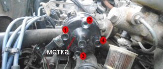
Check if the winding is shorted to ground
This diagnostic stage is done quite simply and will not take much time. The main thing is to connect everything correctly.
- First, we set the position of the pointer of the device for measuring resistance; I think there is no need to explain this in detail.
- Then you need to connect one contact terminal of the device to the central contact on the coil, and connect the second to ground. If you explained something incomprehensibly, then you can see how it all should look visually in practice. The photo below shows everything perfectly.
Checking the ignition module
Checking the ignition module for functionality is carried out in the following ways:
Replacing the ignition module with a known good one
1. The easiest way is to connect a known working module. In this case, the devices must be completely identical, the high-voltage wires are in good condition, and the reliability of the contacts has been checked.
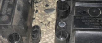
Checking the contacts on the ignition module
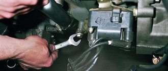
2. Moving the module, which allows you to identify unreliable contacts. To do this, move the wire block and the module itself. If during exposure the engine reacts by changing its operation, then the cause of the problem lies in poor contact.
Measuring resistance at the terminals of the ignition module
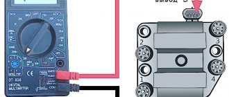
3. Resistance measurement. To do this, you will need a tester switched to ohmmeter mode. Measurements are carried out on the paired terminals of the module between cylinders 1 and 4, as well as cylinders 2 and 3. The resistance value should be the same and approach 5.4 kOhm.
Checking the ignition module using a tester
4. Check the voltage with a tester. One probe of the device is applied to contact A of the block, the second to ground. After turning on the ignition, take readings from the device. If the wire is in good condition, it will show a voltage of 12 V; if it is missing, check the fuse protecting the ignition module. Then check the continuity of the circuit with a 12 V test lamp. Apply one end of the wire to contact A and rotate the starter. If the lamp does not blink, the circuit is broken. The procedure is repeated in a similar way with other contacts.
Diagnostics of the ignition module with professional equipment
5. Diagnostics at a service station by connecting a computer with special software to the computer. Malfunctions are detected in the form of errors indicated by an alphanumeric code, after which a more in-depth diagnosis of the malfunction is carried out to make a decision - repair the ignition module or replace it. A similar check is carried out at a specialized service station using an oscilloscope.
Is the renovation still relevant?
When the symptoms have been identified and the ignition module has been diagnosed, it’s time to decide: try to “save” the old device, or replace it with a new one. The choice is not an easy one, especially considering the fact that repair of the ignition module is possible only on contact connections; in rare cases, it is possible to replace the coil or transistor. For a complete repair we will need:
- Screwdriver;
- Hexagon 5;
- Soldering iron;
- Multicore cable;
- Socket wrenches for 13 and 17;
- Nail polish;
- Flux for aluminum.
We repair the ignition module in the following order:
- We dismantle the device;
- Use a screwdriver to open the case;
- Carefully get rid of the silicone film, which probably covered the entire board;
- All aluminum in the area of explosive contacts is cleaned.
- We remove absolutely all the wires from the board and solder new ones. To do this, clean the surface of the board from plaque and heat it to a temperature of 180 degrees.
- After finishing the work, all contacts, the board and the module itself are varnished.
- The device is mounted in its original seat, and if the final diagnostic results are positive, the ignition module is firmly seated on the sealant.
If you were unable to restore your device, don’t be upset; not everyone can do this task! But now you know exactly how the ignition system works and what it actually is. Moreover, you can easily tell us how to ring the chain, and if necessary, you will take on the repairs yourself. Well, isn't this enough? Looking forward to the next post, but I’m done here! See you later!
Ignition of gasoline in the cylinders of an internal combustion engine occurs using a spark generated by the ignition system. The ignition module is the main element of the system, creating a spark on the spark plugs using high voltage. Each car manufacturer develops and produces its own original module, but the principle of its operation is the same for all devices. During operation, deviation from the specified parameters or breakdown of the ignition module negatively affects engine operation until the power unit fails.
How to diagnose the ignition coil on a VAZ-2114
Diagnostics is carried out in several stages. First of all, the winding is shorted to ground. The multimeter must be set to check the resistance so that it works like an ohmmeter.
Experts note the main symptom of a faulty ignition coil is the absence of an igniting spark on the spark plugs.
Car enthusiasts have repeatedly tried to modify the car's transmission. For example, in tuning the VAZ 2109 brand, the transmission played an important role.
Some gasoline engines that are installed on modern domestic and imported cars are equipped with ignition modules, which are a pulsed high-voltage current source.
The peculiarity of the device is that it uses a spark distribution method, which is called the “idle” spark method. The cylinders are divided into pairs. A spark is produced in each cylinder of the cylinders.
High fuel consumption. Since one cylinder is not working, the remaining three (or more depending on the engine design) take on the entire load. Accordingly, in order to resume the previous power, the motor will require more energy.
Transformers are controlled by a controller using powerful transistor valves. It receives a reference signal from the crankshaft position sensor, on the basis of which the firing sequence of the coils in the block is calculated.
The low cost of the Lada Kalina-1 car determines the rapid wear of spare parts. However, repairing, for example, a VAZ 2109 gearbox with your own hands is quite simple, since parts are much easier to find than for other cars.
In this case, you will need to carry out a different sequence of actions. And below I will try to describe this procedure in more detail:
- It is necessary to connect the device wires to the module contacts, which are located at the edges. That is, to the extreme left and right. You can take a closer look at the photo below.
With new spark plugs, the engine began to run more stable, but after a few days the misfire error popped up again. After some more searching on the Internet, I decided to check the ignition coil and armored wires. You can find out how to do this from the car’s operating instructions; there are detailed instructions there, so I won’t give them here.
Also note that if the car does not start at all, this is not a sign of a coil failure. The fact is that there are several of them in the engine. Usually each cylinder has its own coil. On older ones, voltage is generated on two cylinders at once. Therefore, the motor will work until the last minute. If the car does not start at all, all the coils could fail at once. However, this is unlikely.
Floating speed: The situation when the idle speed of a running engine without any action taken by the driver begins to change spontaneously is called “floating speed”. Moreover, they can vary their performance so much that the engine sometimes stalls.
The weak point of the ignition coils and modules is the secondary winding, which generates a high voltage pulse. A coil break or breakdown may occur in it. The following factors lead to this phenomenon:
- use of low-quality or unsuitable candles;
- operation with non-functioning high voltage wires;
- frequent attempts to check the spark.