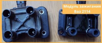
VAZ-2114 ignition module and its features
The passenger car ignition module is specially designed to improve the starting of a car engine.
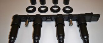
Since two high-voltage coils operate as the main components of the module, it is often called the “ignition coil”. Let's look at the structure of this part:
- coils for generating high voltage;
- two-channel electronic switch;
- durable plastic case;
- low-voltage connector for supplying control pulses;
- terminals for connecting high-voltage wires to spark plugs.
The main operating elements of the ignition module are high-voltage coils that distribute the igniting spark to the spark plugs. This is possible thanks to the following design:
- Wires for high voltage transmission.
- Low voltage terminals.
- The windings on the core are secondary (for igniting the working mixture) and initial.
- Electrical steel core.
The mechanism of operation of the ignition coil is as follows:
- the electronic engine control unit collects all signals from the sensors located on it;
- The ECU generates a control signal;
- the signal goes directly to the ignition coil;
- that, in turn, forms a high-voltage voltage;
- voltage from the coil is supplied to the engine cylinder spark plug;
- the fuel-air mixture ignites;
- the engine starts.
Even an inexperienced car enthusiast can find this part: just trace the path of one of the high-voltage wires - from the spark plug to the plastic case.
This housing houses the ignition module.
High voltage wires
Often, the main difficulty when repairing a carburetor VAZ 2109 is the reconnection of high-voltage wires that were previously disconnected from the distributor cover. It's also an ignition distributor.
The difficulty is that many people forget the connection procedure or simply do not know. But in practice, returning high-voltage wires is much easier than understanding the ignition module used on the injection VAZ 2109.
By following a few simple rules, you can easily return the wires to their rightful places.
- The ignition distributor cover is installed in its place, that is, on the distributor, only in a single position. Therefore, even if you wanted to, you won’t be able to confuse anything here. Otherwise the lid simply won't fit.
- There is an installation mark on the cover, which indicates the location of the wire socket from the first cylinder.
- The wires must be connected in the following sequence - 1, 3, 4, 2. Move counterclockwise when looking at the distributor cover from the side of the expansion tank.
If for some reason there are no installation marks on the VAZ 2109 carburetor distributor cover, just follow the connection principle shown in the image.
VAZ-2114 ignition module: various signs of malfunction
Experts note the main symptom of a faulty ignition coil is the absence of an igniting spark on the spark plugs. But, besides this, there are other signs by which one can judge that the module has failed:
- Lack of dynamics during engine acceleration.
- The appearance of failures in the operation of a car engine at the moment of sharply pressing the gas pedal with your foot so that the vehicle accelerates.
- A noticeable decrease in engine power (as they say, “the engine doesn’t pull”).
- “Swimming” of idle speed.
When the first signs of a malfunction of the described module appear, the owner of the VAZ-2114 should diagnose it. This can be done either independently at home or at the nearest service center for repairing cars of this model.
How to diagnose the ignition coil on a VAZ-2114
As already mentioned, when the first signs of malfunctions appear in the VAZ-2114 ignition module, the vehicle owner should diagnose it. You can perform a similar procedure yourself at home using the following algorithm:
- Check the spark plugs.
- Check the crankshaft position sensor.
- Check the ignition coil.
At home, all stages of the checks can be performed independently. The first stage is checking the spark plugs. It is carried out in the following sequence:
- We remove the spark plugs from their sockets - remove the tips of the high-voltage wires (a special spark plug wrench is suitable for this).
- We examine the candles.
- We clean them from possible soot.
- We set the correct distance between the electrodes.
- We check the spark plugs for operation using improvised means (for example, from a device made from a piezo lighter) or on a car engine with a working ignition system.
If the spark plugs are in good condition, you can proceed to the next stage of checking for faults in the ignition module.
The second step is to check the crankshaft sensor. This test is carried out using a multimeter, thanks to which two characteristics are checked - voltage and resistance. To do this proceed as follows:
- Remove the crankshaft sensor.
- Measure resistance:
- a special ohmmeter mode is installed on the device;
- the terminals of the device are connected to the ends of the winding, which is brought to the surface;
- with optimal sensor operation, digital readings will range from 500 Ohms to 700 Ohms.
- Measure voltage:
- switch the device to the mode for measuring alternating voltage;
- terminals are connected to the ends of the winding;
- any handy object made of metal should be passed along the body of the crankshaft sensor;
- When the sensor operates optimally, the device will show increased voltage readings because there will be a metal object nearby.
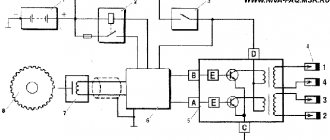
Checking the ignition module (coil) of injection VAZ 21083, 21093, 21099
Due to a malfunction of the ignition module, the following malfunctions may occur in the operation of the injection engine 2111 of VAZ 21083, 21093, 21099 cars: the engine “triples”, “doubles” (works or tries to start on two cylinders), unstable idling, “dips”, “jerks” ", "twitching", etc.
Necessary tools
— Multimeter, autotester or other device with ohmmeter and voltmeter modes
— Socket wrenches or heads for “13” and “17”
Preparatory work
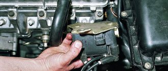
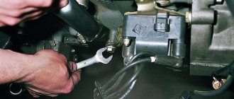
— Remove the ignition module from the engine
Disconnect the ends of the high-voltage wires. Use a key set to “13” to unscrew the two upper fastening bolts, and use a key set to “17” to loosen the tightening of the bottom bolt. Remove the module along with its bracket.
Checking the ignition module (coil) of VAZ 21083, 21093, 21099 cars with injection engine 2111
In garage conditions, you can check the secondary windings of the ignition module for an open circuit and the primary windings for a short circuit, as well as the voltage supply to the module from the ECU. This is quite enough to diagnose its malfunction.
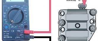
— Check for short circuit
The positive probe of the multimeter in ohmmeter mode to terminal “D” of the ignition module connecting block, the negative probe to the bracket (“ground”). If there is no short circuit, the device readings tend to infinity.
Checking the ignition module for a short circuit
— Check for “break”
Using a multimeter in ohmmeter mode, we alternately measure the resistance between terminals “1” and “4”, “2” and “3” of the ignition module.
Checking the secondary winding of the ignition module for an open circuit
The resistance for each measurement should be within 4 kOhm. If it is different or does not correspond to the required indicator, the module should be replaced.
Checking the secondary winding of the ignition module 2-3 for an open circuit
— Checking the voltage supply to the ignition module
If previous checks did not reveal a malfunction, you need to check the voltage supply to the ignition module. Turn on the ignition. Using a multimeter in voltmeter mode, measure the voltage between terminals “C” and “D” of the block of the wiring harness going to the module (the terminals are marked on the block itself). The voltage must be within the vehicle's on-board voltage (12V). If it is smaller or absent, then the battery may be discharged, the wires from the computer to the ignition module are faulty, or the control unit (ECU) is faulty.
Checking the presence of voltage to the ignition module
Notes and additions
— Often, one of the visual signs of failure of the ignition module can be two wet and two working spark plugs, since the module consists of two pairwise connected ignition coils that alternately produce a spark in two cylinders -1-4, 2-3. The failure of one of the coils leads to the engine running (or trying to start) on two spark plugs.
— The problems listed above in the operation of a car engine may be based not only on a malfunction of the ignition module, but also on a malfunction of the spark plugs, high-voltage wires, as well as the power and control system (ECM).
Source
Methods for preventing the ignition module on a VAZ-2114
Malfunctions of automobile ignition coils on the VAZ-2114 can be avoided if preventive procedures are regularly carried out. These include:
- Periodic unraveling of high-voltage wires (associated with greatly increased internal resistance, as this can damage the module).
- Checking the spark gap between the electrodes of the spark plugs (if the distance between the electrodes changes, this will affect the efficient operation of the ignition coils).
If faulty spark plugs are identified, they are replaced, after which the car will function properly again.
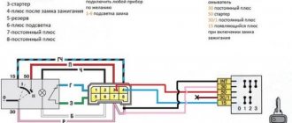
Pinout, connection diagram and check of the VAZ ignition coil
Today we will look at the design and diagrams of ignition systems for VAZ cars of all major models. Since carburetor versions of VAZ are practically history, we will dwell in detail on the ignition systems of injection cars. Their ignition system is based on an electronic ignition module. We also recommend that you carefully consider the choice of spark plugs and the quality of high-voltage wires, because the quality of the spark and, accordingly, the operation of the ignition system as a whole will depend on them. The information is intended as a reference guide for self-repairing a car.
Main function of the ignition module
The main task of the module is to supply current to the spark plugs. During operation, a working spark is supplied to one spark plug, and an “idle” spark to the other. The working spark is supplied to the 1st and 4th cylinders, and the idle spark is supplied to the 2nd and 3rd. Due to this connection, the spark appears in a timely manner in the desired cylinder during the required stroke. It is connected to the on-board network.
Operating principle and location
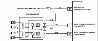
The ignition module is controlled by a controller, which in turn receives information about the state of the vehicle from various sensors (IAC, mass flow sensor and others). The controller also sets the sequence of operation of the ignition coils or, in other words, regulates the supply of current to the spark plugs. The ignition module operates at temperatures from -40° to +130°.
Finding its location is not difficult; high-voltage wires (HV) go from the module to the spark plugs; along them you can find the module.
Operating principle of the ignition switch
The ignition switch, the circuit of which is more complex compared to the first devices for igniting a combustible mixture, has transit keys. This design solution is quite simple and effective. These components are used to control the current flowing through the ignition coil.
It is worth noting that the keys do not affect the operating principle, which is based on electromagnetic induction. Transistors reduce the load on the breaker contacts and increase the current flowing through the winding. This technical change has brought a number of advantages to modern systems, including:
Increased compression ratio.
Increased service life and reliability of the entire ignition system.
Ability to work under increased loads, at high speeds and high engine speeds.
Diagram of the correct connection of wires to the ignition module
If, after checking the wires, you are convinced that they are all tightly connected to the spark plugs, let’s check that the wires themselves are connected correctly. Of course, if no one has climbed into the engine before you, then there is no point in checking. If there was traction and it disappeared, the reason could be both in the coil and in the wires themselves - they could be pierced. But in any case, let's check that the connection is correct. The ignition module shows the numbering of the cylinders to which the wires fit.
- 1 cylinder – central lower outlet
- Cylinder 2 – left output
- Cylinder 3 – top outlet
- 4 cylinder – right output
The diagram is shown for a coil installed on a vehicle.
If after checking no problems are identified, you should consider replacing the coil or wires. It is advisable to change both.
Replacing the ignition module yourself
So, first of all, we are looking for a module (for those who don’t know). The PVNs from the spark plugs go to it.
- Remove the negative terminal from the battery
- Disconnect the wire block from the module
- Disconnect the PVN
- Unscrew the module itself and remove it
- Now install the new module and reassemble in reverse order.
When installing, do not confuse the position of the PVN on the reel.
Helpful note! If you are installing a new coil and old wires, pay attention to them. If there are yellow stripes on the tips of the spark plugs and wires, then the wires need to be replaced.
After replacing the module, you need to check its operation. We start the engine and enjoy the work done.
Repair
Ignition module VAZ 2107
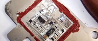
The design of the ignition module is quite complex: it includes one or more coils, a board, contacts and wires. Of all the above elements, only contact connections can be repaired; in some cases, replacement of parts (transistors, coils) is possible.
The module is dismantled and opened for repair purposes. For this you will need:
- Socket wrenches with heads 1, 13 and 17.
- Hexagon 5.
- Screwdriver.
- Soldering iron.
- Flux for aluminum.
- Stranded wire.
- Nail polish.
Opening the ignition module
Repair of the ignition module is carried out in the following order:
- On the removed device, open the case by prying it off with a screwdriver.
- Remove the silicone film covering the board.
- All aluminum is removed from the explosive contacts.
- On the board, new wires are soldered in place of all the dismantled old ones. To do this, the surface of the collector is cleaned of deposits, after which the board is heated to 180 o C (a characteristic smell will indicate when the desired temperature has been reached). During the soldering process, the ends of the wires are connected to the module.
- At the end of the operation, all contacts, the board and the module are covered with nail polish.
- The device is assembled in the reverse order, installed on the car and the engine is started. In case of normal operation, the ignition module is sealed tightly with sealant, while the wires are tucked inside the cavity so that they are not pinched at the edges by the plate.
If the device does not work, then a breakdown inside the module should be looked for more carefully. The transistor, electronic component may have failed, or there may be a break in the coil. Such a repair makes sense only if its price is significantly lower than the cost of a new part.
How to Check the Ignition Module of a VAZ 21099 Injector
Replacing the ignition module on a VAZ 2108, VAZ 2109, VAZ 21099
The ignition module on Samara cars was equipped with a module and an ignition coil, there are differences in these two things, although many say that they are the same, for example, the ignition module was installed on more modern injection cars and consists of two coils and one large ignition coil used on cars with a carburetor, which first applied voltage to the distributor and then the spark came from the distributor. high voltage wires and for spark plugs in injection machines a distributor is not used, they only use high voltage wires and spark plugs, thus remaining an injection system and is a more modern technology that has replaced carburetor machines.
To replace this unit, you will need to stock up on: wrenches, cap screws, all you need is a cap and an extension, but only if you don't have a collar!
Where is the ignition module located?
It is located on a bracket and attached to it with three nuts, so immediately decide how to remove the module from the car together with the bracket or separately from the bracket (the module is easier to remove with the help of a bracket), so return to the topic, the module is located deep in the engine, and its the location is not very convenient, for clarity in the photo below it is indicated by a red arrow, and the other one in the photo below the spark plug is indicated by a blue arrow, so first find the spark plugs in the car and then find the module just below.
When should I replace the ignition module?
There are two coils in the module, and if one of them fails, the machine will start to stomp a lot, the machine will zero out a lot, the machine will have a very hard time accelerating at the same time, and the machine will double for the whole thing (just doubly so, this is not a printing press , two cylinders will not fit) to all this, the noise of the engine during its operation will increase and, therefore, the sound of operation will not change very well, you will understand this immediately.
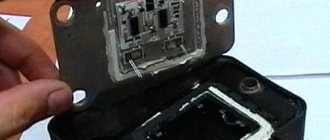
How to replace the ignition module on a VAZ 2108-VAZ 21099?
1) Removing the module is not difficult, but there will be problems with checking it, because this requires, first of all, special equipment, although you can use a standard multimeter to check the health module (Jas module You can check this, we will describe it in the same article), but first you need to remove it, first disconnect the wire block from the module (see Photo 1) attached to the latch, so be sure to bend the latch on the block otherwise you may tear it off, once the device is detached, take the wrench in your hands and use it to completely unscrew the top bolt (see photo 2) securing the module, and then unscrew the side of the nut (see photo 3). , it is marked with a red arrow) so that you don’t lose the bolt, you can remove it like this, well, in your head. Go to the bottom (under the car if possible) and locate the last module mounting bolt at the bottom (see Photo 4, bolt marked with arrow), loosen this bolt slightly and then completely remove the ignition module from the car, disconnecting everything connected to four wires, otherwise they will not allow you to remove the module from the car.
Models, design and characteristics of VAZ switches
Electronic switches used on VAZ cars are divided into two large groups:
- Transistor;
- Based on specialized microcircuits.
The structure of a modern VAZ switch Typical connection diagram for an electronic switch
The simplest design is transistor switches, which were historically the first (they replaced contact-transistor devices that were widely used on VAZ Classic cars). In essence, this is an electronic key, complemented by a signal amplifier from the pulse sensor, as well as protection and temperature compensation elements. The key is built on one powerful transistor, which is controlled by one or two transistors that amplify and change the signal from the Hall sensor. Zener diodes included in the circuit (prevent voltage surges), thyristors (disabling the switch or its individual elements in emergency modes) and other parts can act as protection elements. And temperature compensation elements (chains of resistors and capacitors) ensure constant operating modes of semiconductor devices over the entire permissible temperature range.
The operation of a transistor switch is quite simple. While there is no signal from the Hall sensor, the electronic key is open and a direct current flows through the primary winding of the coil - at the moment there is no current in the secondary winding. When a signal is received from the sensor, the switch closes, interrupting the current in the primary winding. Due to the presence of inductance, the current in the primary winding does not drop to zero instantly, but over a certain period (fractions of a second), the phenomenon of electromagnetic induction occurs - as a result of this effect, high-voltage alternating current also appears in the secondary winding. This current flows through the distributor to the spark plug, where sparking and ignition of the combustible mixture occurs. At a subsequent moment, a direct current again flows through the primary winding, so the current disappears again in the secondary winding. Then the described processes are repeated again up to 200-300 times per second.
Transistor circuitry is incorporated into the switch model 76.3734. This device is simple and reliable, but it has a number of disadvantages. For example, as the crankshaft rotation speed increases, the current in the secondary winding decreases significantly; the switch also has limited functionality and cannot ensure efficient operation of the ignition system in all modes.
Electronic switches based on specialized microcircuits do not have these disadvantages. This switch also uses an electronic key on a powerful transistor, but the key control is assigned to a microcircuit, which significantly expands the functions and capabilities of the entire device. In particular, switches with microcircuits implement functions for regulating the time of energy accumulation in the coil, spark-free cutoff (limiting spark formation when the ignition is on but the engine is stopped), various levels of protection, and others. Thanks to the ability to regulate the energy storage time, switches on microcircuits provide stable sparking throughout the entire crankshaft speed range, which is why they are so widespread.
Switches of models 036.3734, 42.3734, 72.3734 (all on domestic element base) and their modifications, 98.3734, German HUCO.13 8090 and others (on foreign microcircuits) are built on microcircuits.
Electronic switches are divided into two more types according to the number of control channels:
All the devices described above are single-channel. They are designed to work with one ignition coil, so in systems with two coils it is necessary to use two identical switches working with one pulse sensor. Dual-channel switches are specialized devices for controlling two ignition coils at once. Devices of this type include the switch model 133.3774 of some modifications.
Structurally, all VAZ switches are made in the form of compact plastic blocks with integrated aluminum heat sinks (they provide cooling of the powerful transistor during operation of the ignition system). The heat sinks have lugs or holes for mounting screws; with their help, the switch is mounted on a bracket or directly on the car body. The switch is connected to the electrical system using one standard connector with knife-type contacts located on the housing wall.
The main characteristics of electronic ignition system switches include:
- Switching current;
- Limiting crankshaft rotation speeds at which uninterrupted sparking is ensured;
- Permissible and maximum supply voltage;
- Spark-free cut-off time.