Required Tools and Process
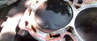
From time to time, the cylinder head gasket may fail due to wear and tear of its material or burnout. The main signs that it is time to replace the gasket with a new one are the appearance of local leaks of oil and coolant at the point of contact between the cylinder head and the engine. Tightening torque of the cylinder head VAZ 2114 8 valves: consider the subtleties of the process.
It should be remembered that when replacing a gasket, not only the tightening torque of the VAZ 2114 cylinder head is important, but also the entire sequence of operations - after all, the replacement itself is a very important and serious procedure, errors during which can lead to engine malfunction.
In order to do it correctly, you will need:
- set of socket heads;
- extension;
- ratchet/wrench;
- torque wrench.
The replacement process itself should be performed according to the following scheme:
- Disconnect the wires leading to the emergency oil level and coolant temperature sensors.
- Drain the coolant.
- Remove the thermostat.
- Remove the air filter housing.
- Disconnect the exhaust pipe inlet from the manifold.
- Remove the casing, as well as the camshaft belt itself.
- Disconnect the drive rods of both dampers from the carburetor.
- Disconnect the wires going to the cylinder head.
- Disconnect the hoses suitable for the cylinder head by loosening their clamps.
- Remove the cylinder head.
- Remove the worn gasket.
- Clean the contact surface of the cylinder head from any remaining gasket material.
Installing the gasket and mounting the cylinder head in place is carried out in exactly the same sequence, but in reverse order. At the same time, it is worth paying close attention to such a factor as the tightening torque of the cylinder head of the VAZ 2114 8 valves - we will talk about it below.
Brief information
The valves have a simple design and are highly wear-resistant. The latter is due to the manufacturing material, which must withstand increased loads.
The valve itself consists of several sections:
- plates (lower expanded part of the part);
- rod (the upper narrow part of the part, going from the plate upward);
- chamfers (the place where the plate adheres to the cylinder block);
- plate edges;
- the end of the rod (its upper part located above the groove);
- recesses for crackers (small groove under the end).
The contact point between the plate and the cylinder head is called the seat. It is made of steel or cast iron and pressed into the cylinder head.
According to their purpose, valves are of two types:
Inlet
Responsible for supplying the air-fuel mixture to the cylinder-piston system. They have a solid rod and, usually, a larger diameter plate to improve working properties.
High school graduation
Responsible for the removal of exhaust gases during the operation of the internal combustion engine. The stem of this type of valve is made hollow; Sodium is placed inside it. This design allows the exhaust valve to be cooled, since it is subject to higher heat than the intake valve. For its production, heat-resistant metal is necessarily used.
Why is there a need to replace valves?
Under normal operating conditions, valves may need to be replaced due to wear. This happens after about 300 thousand km.
There are usually two reasons for the need for unscheduled replacement: burnout and deformation.
Premature burnout can happen due to:
- constant driving at the highest possible speed and, as a result, a knocking engine;
- frequent refueling with low-quality fuel;
- incorrectly adjusted gap (the gap is too small and the heat dissipation is impaired);
- inappropriate number of spark plugs, etc.
The valve becomes deformed when the timing chain breaks or when it moves several links (this happens when the tension is poor). As a result, the rod bends, which leads to a loose fit of the plate to the seat.
How to tighten cylinder head bolts correctly?
Before you begin installing the cylinder head, you should first pay attention to the condition of its bolts. They must have a good thread and the length meet the required standards.
The normal overall length of the cylinder head bolt is 135.5 mm. If the bolts removed during gasket replacement meet this parameter, they can be reused. If the bolts have lengthened during engine operation, then they can no longer be used and new ones should be purchased.
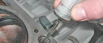
Having dealt with the bolts in this way and installing them in place, you should proceed to tightening. It must be done only with a torque wrench. Tightening bolts “by eye” can lead to very serious consequences, including damage to the engine itself.
And so, how to stretch the head onto a VAZ 2114 correctly? Firstly, you should remember that you should start tightening the bolts from the center to the edges.
Secondly, tightening should be done in four stages (each of which is performed in exactly the same sequence as indicated in the diagram above).
At the first stage, we tighten each of the bolts with a torque wrench with a force equal to 2 kgf/cm2.
At the second stage, we tighten all the bolts with a force of 8 kgf/cm2.
At the third stage, we tighten the bolts, turning each of them at an angle of 90 degrees.
At the fourth stage, we again turn each of the bolts (still following the diagram given at the beginning) at an angle of 90 degrees.
Once all four steps are completed, tightening the cylinder head bolts can be considered complete.
The tightening of cylinder head bolts should be taken as seriously as possible. All its stages must be performed strictly in the same order and with equal effort at each of them. Failure to comply with this rule can lead to rapid wear of the gasket and the appearance of oil and coolant leaks.
breather VAZ 2112 16 valves - hello. thank you very much. I have a VAZ 2112 - 22 answers
In the Service, Maintenance, Tuning section, hello to the question. thank you very much. I have a VAZ 2112 asked by the author Ask for the best answer It may have overheated and the rings are stuck.
Reply from 22 replies Hello! Here is a selection of topics with answers to your question: Hello. thank you very much. I have a VAZ 2112 Reply from Alexander Sudorgin overfilled the oil Reply from Eurovision On the upper plane of the head, the valve drive parts are fixed, which are covered with a lid with a cap. A breather is mounted on the cap. It communicates the crankcase cavity with the atmosphere. The breather is necessary to prevent oil from being squeezed out through the crankcase seals by gases penetrating from the cylinders. Air and gases that have escaped from the cylinders into the crankcase come out through the breather. If, after stopping the engine, the pressure of the cooled air in it becomes below atmospheric pressure, the air enters the crankcase from the outside through the breather. Wire packing soaked in oil cleans the air of dust. In some engines, the breather is located on the side wall of the block (from the side of the rod chamber) or in the neck cover for pouring oil into the crankcase. Most car engines have forced crankcase ventilation. A pan is attached to the bottom plane of the crankcase, which serves as a reservoir. In general, check the oil level)) Answer from Ashera? Is this when they started installing the Priora engine on the VAZ 2112? 16 valves does not mean at all that it is a Priora one. And how did you notice this oil? The breather drives gases into the spider and not into the air vents. There are 2 breathers. Which one does it drive from? Most likely, the partition between the rings on one cylinder has burst. Answer from Theosophy: Check the crankcase ventilation system, there should be a primitive oil separator, so check it first of all with engine diagrams on the Internet, so start by studying the hardware.
The engine crankcase ventilation system 2111 of VAZ 2108, 2109, 21099 cars with fuel injection is designed to effectively remove gases from its crankcase and burn them in the combustion chambers. As a result, the emission of harmful substances into the atmosphere is reduced.
Design of the crankcase ventilation system for engine 2111 (diagram)
1. Engine crankcase.
3. Hose from the breather to the valve cover pipe.
4. Oil separator under the valve cover.
5. A thin hose from the valve cover to the fitting with the throttle body nozzle.
6. Fitting with a jet on the throttle valve block.
7. Thick hose from the valve cover to the inlet pipe.
Operating procedure for the 2111 engine ventilation system
— At idle, with the throttle valve closed, crankcase gases under high vacuum are sucked through the breather and its hose under the valve cover to the oil separator. Further, under the influence of the same vacuum, through a thin hose from the valve cover to the fitting with the nozzle into the throttle assembly, under the throttle valve and further into the combustion chambers (small branch). The jet limits the amount of crankcase gases entering at idle, as normal operation in this mode may be disrupted.
— In operating and power modes, when the throttle valve is slightly open and more efficient crankcase ventilation is required, crankcase gases also flow through the breather, its hose, to the oil separator under the engine valve cover. And then they are sucked through a thick hose from the valve cover into the intake pipe to the throttle body (large branch). Crankcase gases practically do not flow through a thin hose, since when the throttle valve is open, the vacuum behind it drops significantly.
Engine crankcase ventilation system malfunctions 2111
— The main and most common malfunction of the ventilation system is clogging. A clogged crankcase ventilation system can lead to negative consequences in the operation of the car engine. The hoses or oil separator or jet in the throttle assembly may become clogged.
The consequences may be the following:
— violation of the normal operation of the engine at idle (increasing the idle speed control steps more than normal - the speed increases);
— engine oil leaking from under the engine seals (as excess pressure is created in the crankcase);
— oil contamination of the engine air filter and, accordingly, a drop in power plus an increase in fuel appetite;
— contamination of the engine itself with tar deposits.
If, while operating a LADA car, you notice that during load (when the air conditioner is running, the heating is on, etc.) in a traffic jam, the engine begins to operate unstably (troits, pulls poorly, etc.), perhaps the reason lies in the ventilation system crankcase The article proposes to solve the problem by installing a PCV valve from a foreign car.
conclusions
Replacing the head gasket on a VAZ-2114 is quite difficult, since you need to know the design features of this engine, as well as have experience in performing such operations on similar engines.
The choice of gasket should be approached seriously and carefully, since the normal operation of many components depends on its condition. If the process described in the article seems quite complicated and the motorist is not able to carry out the operation on his own, then it is recommended to contact a car service center, where they will help and do everything quickly and efficiently.
Characteristics of motors 2114
Since the release of the Lada Samara VAZ-2114, the technical characteristics of the gasoline drive have been constantly improved. Owners of domestic cars, in principle, do not have questions about what kind of oil to pour into the engine, since standard requirements apply for Zhiguli, Lada and Samara - 5W30 or 10W30.
In addition, you should know what kind of oil to use in transmission gears - the instructions from the AvtoVAZ manufacturer recommend using the GL-4 group of lubricants with a viscosity of 80W85 (mineral), 75W90T (synthetic) or 85W90 (semi-synthetic).
After filling with synthetics, the box becomes noisy, the oil is more expensive, but the lubricant is mostly imported, which provides additional guarantees. Domestic manufacturers most often produce semi-synthetics of average quality for engines and transmission gearboxes.
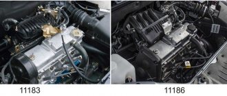
The technical characteristics of the engine are as follows:
| Characteristics | Engine modification | ||||||||
| 2111 | 21114 | 11183 | 21124 | 21126 | |||||
| Years of installation | 2003 – 2007 | 2003 – 2007 | 2007 – 2009 | 2009 – 2013 | 2009 – 2013 | ||||
| Volume | 1500 cm 3 (97.9 hp) | ||||||||
| Torque moment | 115.7 Nm (3200 rpm) | 125 Nm (3000 rpm) | 120 Nm (3200 rpm) | 131 Nm (3700 rpm) | 145 Nm (4000 rpm) | ||||
| Weight | 127.3 kg | 112 kg | 112 kg | 121 kg | 115 kg | ||||
| Compression ratio | 9,8 | 9,6 | 9,6 | 10,3 | 11 | ||||
| Nutrition | injector | ||||||||
| Engine diagram | Inline (L) | ||||||||
| Ignition | module | coil | coil | coil for each spark plug | |||||
| Number of cylinders | 4 | ||||||||
| Location of the first cylinder | TVE | ||||||||
| Number of valves on each cylinder | 2 | 2 | 2 | 4 | 4 | ||||
| Cylinder head material | aluminum alloy | ||||||||
| Intake manifold | aluminum | plastic with receiver | |||||||
| An exhaust manifold | with catalyst | ||||||||
| Camshaft | 2110 | 2111 | 2112 | ||||||
| Cylinder diameter | 82 mm | ||||||||
| Piston stroke | 71 mm | 75.6 mm | |||||||
| Pistons | Yes | No | No | Yes | No | ||||
| Valve bend | Yes | No | No | Yes | No | ||||
| Crankshaft | 2112 | 11183 | |||||||
| Fuel | AI-95 | ||||||||
| Environmental standards | Euro 4 | Euro 2 – 4 | Euro 3 – 4 | ||||||
| Fuel consumption highway/combined cycle/city | 5,7/7,3/10 | 6/7,3/10,4 | 6/7,8/11 | 5/7/9,5 | 5,4/7,2/9,8 | ||||
| Oil consumption per 1000 km | 0,7 | 0,5 | |||||||
| Engine oil for 2114 | 5W-30 and 10W-30 | ||||||||
| Engine oil volume | 4 l | 3.8 l | 3.5 l | 3.6 l | |||||
| Operating temperature | 95° | ||||||||
| Motor life | declared 150,000 km, real 250,000 km | ||||||||
| Adjustment of valves | washers between camshaft cams and tappets | hydraulic pushers | |||||||
| Cooling system | forced, antifreeze/antifreeze | ||||||||
| Coolant quantity | 7.8 l | ||||||||
| water pump | plastic impeller | ||||||||
| Candles for 2114 | A17DVRM, BPR6ES | AU17DVRM, BCPR6ES | |||||||
| Gap between spark plug electrodes | 1.1 mm | ||||||||
| Timing belt | length 698 – 1125 mm depending on attachments | ||||||||
| Cylinder operating order | 1-3-4-2 | ||||||||
| Air filter | Nitto, Knecht, Fram, WIX, Hengst | ||||||||
| Oil filter | Mann W914/2 | ||||||||
| Flywheel | 2110 | ||||||||
| Flywheel mounting bolts | M10x1.25 mm, length 26 mm | ||||||||
| Valve stem seals | code 90913-02090 inlet light code 90913-02088 exhaust dark | ||||||||
| Compression | from 14 bar | ||||||||
| XX speed | 750 – 800 | 800 – 850 | |||||||
| Tightening force of threaded connections | spark plug – 31 – 39 Nm clutch bolt – 54 – 87 Nm bearing cap – 59 Nm (main) and 43 – 53 Nm (rod) cylinder head – four stages 20 Nm, 71 Nm + 90° + 90° | ||||||||
For high-quality maintenance of internal combustion engines, the engine manufacturer issues a manual containing a description of the drive parameters, the frequency of replacing consumables and step-by-step repair operations. The same operating manual recommends the volume of oil in the gearboxes in the engine.
Tightening torque of the cylinder head VAZ 2114 8 valves: correct operation with a torque wrench
A tool such as a torque wrench, which allows you to tighten bolts with equal force, requires great care in operation and certain skills.
An approximate sequence for tightening bolts with this wrench is as follows:
- set the holder to the “zero” position;
- begin smooth rotation of the instrument, while simultaneously monitoring its readings;
- if the tool rotates (especially at the initial stage of tightening) without changing the torque on the indicator, this may indicate a slight internal stretch of the fasteners. This phenomenon is absolutely normal and the rotation of the tool should be continued;
- When the tightening torque corresponding to the required one is reached, the movement of the tool should be stopped.
Instead of using a torque wrench, you should not use any other tool (including a mechanized one, with the ability to regulate the tightening force). After all, only with a wrench can you achieve absolutely precise and smooth tightening of the bolts, thanks to which the gasket will be evenly pressed over the entire surface of the block. This will help maximize its service life, avoid burnouts, oil leaks and coolant leakage.
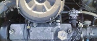
What does the cylinder head consist of?
The cylinder head is designed the same on any type of engine. It consists of:
- housing (head), in which the channels of the oil and cooling systems pass;
- intake and exhaust valves;
- one or two camshafts.
The housing is the main element of the cylinder head. It circulates lubricant and coolant and is the basis for camshafts and valves. If the cylinder head housing is correctly secured to the engine block, then all engine systems operate normally.
If the cylinder head is not tightened evenly, then there is a high probability of cracks forming in the head housing. The cylinder head is made of aluminum, and the mounting bolts are made of steel. Therefore, the thermal expansion of the head and bolts is not the same.
If any part of the cylinder head is not tightened well, this will lead to stress in it, because one part of the head will increase more than the other.
Procedure for replacing the cylinder head gasket on a VAZ 2109-2108
The gasket may remain either on the surface of the head or stick to the block itself. You can try to remove it by hand without using any tools, and if that doesn’t work, you can carefully pry it off with a flat-head screwdriver without damaging the surface of the part.
The engine block also needs to be cleaned and then a new gasket installed on it.
Of course, it will be necessary to first carry out some preparatory procedures, without which it will be impossible to remove the head.
- First, you need to remove the air filter housing
- Then disconnect all fuel hoses and power wires from the carburetor or injector (depending on the type of engine)
- , although this is not a prerequisite - it will be enough to disconnect the high-voltage wires
In general, it is necessary to free the head from everything unnecessary so that during dismantling there are no unnecessary problems. Of course, if you decide to completely replace it or repair it, then you will have to perform more operations, both the carburetor and the manifolds. Well, if it’s just a matter of gasketing, then you can get by with a minimum of actions.
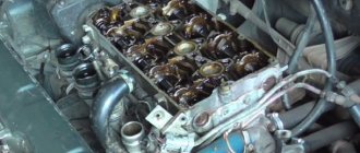
Removing and disassembling cylinder covers.
First remove the high pressure pipes (to the injector), the valve box, the drive rods and the exhaust and intake manifold pipes. After this, the cylinder covers are evenly loosened and then the stud nuts are unscrewed. In order to protect them and the crankshaft from damage, safety shields are placed on the cylinder liners. When disassembling the covers and lever mechanism, the parts are not disassembled unless they require replacement. If wear exceeds the permissible value, the valve guides, lever heads and sockets (11D45) are pressed out of the cylinder cover.
Cars VAZ-2115i-14i-13i
The tightening torques for threaded connections on VAZ-2115 (2113, 2114) vehicles are given in the table below.
- The given values of tightening torques for threaded connections can be rounded to tenths within the tolerance.
- The cylinder head mounting bolts must be tightened in four steps: 1 – to a torque of 20 Nm (2 kgf); 2 – torque 69.4–85.7 (7.1–8.7 kgf); 3 – turn 90°; 4 – turn it 90° again.
Tightening torque, Nm (kgf-m)
Assembly Features
Before assembly, you should check the bolts securing the head to the hood; their length should not be more than 13.5 cm; if they are longer, they can no longer be used.
You should also check the flatness of the head. If it was overheated, it is possible that it was warped and will require repair in the form of trimming the plane.
During assembly, the head bolts are tightened in a certain sequence and with a strictly defined tightening torque. Next, everything is assembled in the reverse order of disassembly.
Disassembly is also carried out in the same sequence if the power plant is being modified.
Conversion kit for an 8-valve injection engine to a 16-valve engine. You can check prices here www.tltzap.ru/price.html#1
The kit includes: price: 1. Cylinder head 21126 assembled.___________________17,000 2. Timing casing.___________________________1000 3. Timing rollers___________________________500 4. Timing belt 2112______________________________250 5. Water pump 2112________________550-1000 6. Bare fuel rail with tube 7. Injector wiring 8. Pistons 21124 82.0____________________1000 9. Piston pins 2110______________50-75 10. Retaining rings_____________1-25 for 1 piece 11. Modified cylinder head bolts 2108___________40 for 1 piece 12. Intake receiver____________________4500 13. Exhaust manifold gasket_______2-36 for 1 piece 14. Exhaust manifold (spider 4 -2-1)_______1800 15. Modified cylinder head gasket__________ 16. Oil dipstick________________________75 17. Aluminum breather____________780 18. Lower breather hose (thick) 2112_____30 19. Damper 2112_______________________550 20. Crankshaft pulley 2112____________870 2 1. Valve cover 21126______________1400 22. Timing pulleys__________________________950 23. Coils ignition 24. Ignition coil wiring 25. Spark plugs 2112 26. Crankshaft bolt 27. Camshaft bolts 28 Camshaft bolt washers 29. Valve cover bolts 30. Timing roller nuts 31. Timing roller washers 32. 4mm alignment washers for the rollers. 33. Timing cover mounting bolts. PS: Pistons can be replaced with sizes 82.4 and 82.8.__770-2950 per set
Procedure for replacing the cylinder head gasket on a VAZ 2109-2108
At the end of the operational period or if the integrity of the cylinder head gasket is damaged, the element must be replaced.
The main sign of a malfunction or gasket wear is the formation of coolant and oil leaks at the junction of the engine block and the cylinder head.
Cylinder head seals
Replacement
To change the gasket, you will need to dismantle the assembly, get rid of the worn cylinder head gasket and reassemble the structure in the reverse order, following the recommendations regarding the tightening torques of the cylinder head bolts. We will tell you about all this in more detail.
Cylinder head seals
If you detect a leak of engine oil or coolant at the junction of the head and the cylinder block, remove the head and replace its gasket. A leak can also occur due to warping of the block head due to overheating.
You will need: a torque wrench, keys “13”, “17”, “19”, socket heads “10”, “13”, “17”, “Togh”, screwdriver.
Warning! The head gasket is a one-time use unit, so the gasket must be replaced each time the head is removed.
1. Disconnect the wire from the “-” terminal of the battery.
2. Set the piston of the 1st cylinder to the TDC position of the compression stroke (see “Installing the piston of the 1st cylinder to the TDC position of the compression stroke”).
4. Reduce the pressure in the power system if the work is performed immediately after a trip (see “Reducing pressure in the power system.”
5. Disconnect the exhaust pipe of the muffler from the exhaust manifold (see “Replacing the exhaust pipe”.
6. Remove the cylinder head cover (see “Replacing the cylinder head cover gasket”).
7. Disconnect the wiring harness block from the mass air flow sensor, loosen the clamp securing the air supply pipe to the throttle body and remove the pipe with the air filter housing and the air intake hose from the throttle body (see “Removing and installing the air filter”).
8. Unscrew nut 1 securing the bracket for the water pump supply pipe. Loosen nut 2 securing the inlet pipe bracket to the exhaust manifold.
9. Move the bracket to the side.
10. Loosen the clamps.
11. ...and disconnect the inlet and outlet hoses of the cooling system from the throttle body.
12. Loosen the clamp securing the vacuum brake booster hose to the fitting on the receiver...
13. ...and remove the hose.
14. Turn the throttle drive sector all the way and disconnect the throttle drive rod from it.
15. Unscrew the two nuts securing the tips of the “mass” wires to the rear cover of the cylinder head...
16. ...and remove the wires from the studs.
17. Unscrew the nut of the lower fastening of the spacer 1 and remove the bolt of the lower fastening of the spacer 2...
18. ...unscrew the nuts of the upper fastenings of the intake manifold struts on the right...
19. ...and on the left side, remove the spacers.
20, Disconnect the wiring harness connectors from the crankcase oil level sensors...
21. ...from the throttle position sensor...
22. ...from the idle air control...
23. ...from the injector wiring harness...
24. ...from the coolant temperature sensor...
25. ...from the crankshaft position sensor and the knock sensor.
26. Disconnect the wire connectors from the coolant temperature gauge sensor...
27. ...and from the oil pressure sensor.
28. Disconnect the high-voltage wire tips from the spark plugs.
29. Pull the wiring harness out from under the receiver.
30. Remove the three screws securing the front camshaft drive belt cover, remove the cover...
Warning! It is forbidden to turn the crankshaft and camshaft before installing the camshaft belt.
32. Secure the camshaft toothed pulley from turning, remove the bolt securing the pulley to the camshaft...
33. ...and remove the bolt and washer.
34. Remove the pulley from the camshaft. Do not damage the camshaft oil seal.
Note. If the key does not sit tightly in the groove of the camshaft nose, remove it so as not to lose it.
35. Unscrew the nut securing the rear camshaft drive cover at the top of the cylinder head.
36. Remove four bolts (three of them also secure the water pump) and remove the rear cover (see “Engine repair (disassembly, troubleshooting, assembly)”).
37. Unscrew the nut securing the “mass” wire...
38. ...and remove the wire from the stud securing the exhaust pipe of the cooling system to the cylinder head.
39. Loosen the clamps and remove the radiator inlet pipe 2, the inlet hoses of the throttle unit 4 and the heater 3 from the outlet pipe, disconnect the thermostat 5 along with hose 1.
40. Unscrew the fastening nuts and disconnect the fuel supply and drain hoses from the fuel pipes, holding the hoses from turning with a second wrench.
41. Please note that there are O-rings installed on the fuel pipes.
After disconnecting each hose, remove the O-ring from the tube. Replace heavily compressed or torn rings.
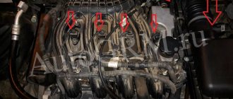
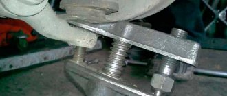
42. Loosen the ten bolts securing the head of the unit in the order shown, then completely unscrew the bolts securing the head, remove them along with the washers and remove the head.
Note. It is necessary to unscrew the cylinder head mounting bolts using a special socket head “Togh”.
Warning! Do not jam a screwdriver or other tools between the cylinder head and the cylinder block.
Helpful advice. To remove the cylinder head from the gasket, insert a screwdriver under the exhaust manifold. Using it as a lever, lift the head.
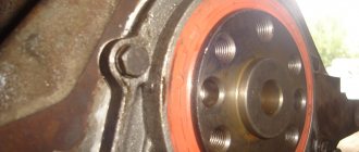
43. Remove the head gasket.
Note. The cylinder head bolts become stretched with repeated use. Replace with new bolts longer than 135.5 mm. Before installing the cylinder head, lubricate the bolts with a thin layer of engine oil.
44. Clean the mating surfaces (they must be dry and clean) of the cylinder head and cylinder block and remove oil from the threaded holes in the block for the head mounting bolts.
45. Install a new head gasket on the block (the gasket must be dry and clean) along the installation sleeves so that the hole for the oil passage in the gasket (with copper edging) is between the 3rd and 4th cylinders.
1 - torque 20 N-m (2 kgf-m);
2 - torque 69.4-85.7 Nm (7.1-8.7 kgf-m);
3 - tighten the bolts 90°;
4 - finally tighten the bolts 90°.
47. Install the parts on the cylinder head and connect hoses and wires to it in the reverse order of removal. Install the camshaft pulley with the protruding part of the hub facing the engine.
Check and, if necessary, adjust the clearances in the valve drive (see “Adjusting the clearances in the valve drive”). Adjust the tension of the camshaft drive belt (see “Replacing the camshaft drive belt and adjusting the belt tension”).
Replacing valve stem seals - pro tips
I decided to replace the valve stem seals, the reason was the spark plugs, or rather their condition, and recently there was smoke when starting up when cold and too much oil.
As they say: the eyes are afraid, but the hands do)))
As it turned out later, the cause of the plaque on the fourth spark plug was the caps falling off, both of them.
Prepared the tool
An approximate list of what is needed.
Unscrew and disconnect everything that gets in the way, remove the valve cover.
We remove the camshaft pulley, two housings, and the camshaft itself.
We remove oil and dirt.
We provide access to the crankshaft pulley and set the top dead center of cylinders 1 and 4.
We fix the valve we need with tin.
TRIALLI valve stem seal set from old stock.
Bushings for putting on, so as not to damage the grooves of the cracker. You need to remove the spring from the seals and dip them in oil.
We change the seals on cylinders 1 and 4.
We put on the bushings and the seals themselves.
We press in the bushing and put on the springs.
We put the pushers and adjusting washers in their place, the main thing is not to mix them up.
We turn the crankshaft and do the same with the 2nd and 3rd cylinders.
Lubricate all rubbing elements with oil.
At the same time I changed the camshaft seal, just in case)))
We install the camshaft, the cams of the first cylinder should point to the sides, put on the oil seal and apply sealant to the corners.
On the other hand, it also needs to be lubricated with sealants.
We install a new lid ring, lubricating it with sealants.
We install the camshaft housings, rear cover and pulley, not forgetting the key.
We catch the mark on the flywheel
Place a mark on the pulley, put on and tension the belt
To put your mind at ease, you can check the gaps)
We collect and connect everything necessary to start the engine, then we try envy.
If all is good.
We install and screw everything else... and that's it)))
On cylinder 4, both caps fell off, on the rest, the exhaust caps were removed by hand, and the intake caps were removed with a puller; all caps were hard.
After the replacement, there were already a couple of morning starts and I didn’t notice any smoke like before), I also unscrewed the spark plugs and everything was fine too. In general, everything seems to be good, I think time will tell.
Reinstalling the head
Photo and video instructions for those who plan to independently remove and install the cylinder head on a VAZ 2114, 13, 15.
The cylinder head is removed to repair it, to replace the head gasket, and also during major engine overhauls.
- We wash the cylinder head from dirt and deposits with kerosene or diesel fuel.
We remove any remaining oil and coolant from the threaded holes of the cylinder block (under the cylinder head bolts).- We clean the landing surfaces of the head and cylinder block from the remnants of the old gasket, and degrease the surfaces with a solvent. Always use a new gasket when installing the cylinder head. Oil should not come into contact with the surface of the gasket.
- We install the head guide bushings into the mounting hole of the cylinder block.
Sequence of tightening the cylinder head bolts - We place the gasket on the cylinder block, and the guide bushings should fit into the corresponding holes in the gasket.
- We install the head on the cylinder block. By slightly moving the head from side to side, we ensure that the guide bushings fit into the corresponding holes in the head. Reuse of cylinder head bolts is permitted only if their length does not exceed 135.5 mm.
- Using a caliper or a mechanic's ruler, measure the length of the bolts. Bolts longer than 135.5 mm are replaced.
- Before screwing, dip the threaded part of the bolts into engine oil, then let the oil drain, waiting for about half an hour.
- Install bolts and washers into the holes in the head.
- Using a torque wrench, tighten the head mounting bolts (in the sequence shown in the photo) in four steps: – tighten the bolts to a torque of 20 Nm (2 kgf m); – tighten the bolts to a torque of 69.4–85.7 Nm (7.1 –8.7 kgf m);– turn the bolts by 90°;– turn the bolts again by 90°.11. We perform further assembly in reverse order.
10. Loosen the clamps.
Now you can carefully install the cylinder head in its place, making sure that at this moment the gasket does not slip out or move to the side. Of course, the guides fix it, but you should still be extremely careful.
Now regarding the force with which it is necessary to tighten the bolts. This should be done in 4 steps:
- First, a torque of 20 Nm
- Second reception with a torque of 75-85 Nm
- Tighten each bolt another 90 degrees.
- Finally turn it 90 degrees.
After this, all that remains is to install all the equipment removed from the car, fill in the coolant, connect all the sensors, wires and hoses and check the work done. Usually everything becomes visible immediately after pouring antifreeze. If wet marks appear at the junction of the head and block, you can take everything back and do the whole job again! But I hope that this will not happen in your practice! Happy renovation!
How to properly remove valves
Before you begin, you need to prepare the appropriate tool. In particular, to replace you will need:
- Set of socket and open-end wrenches.
- Torque wrench.
- Spare parts for replacement (new set of valves, gaskets if oil seals need to be replaced, etc.)
- Container for draining antifreeze.
Initially, the machine must be de-energized. This is done by removing the negative terminal from the battery; the next step is to free the cooling system from antifreeze. Drain the coolant into a specially prepared container; releasing pressure in the fuel system. To do this, you need to unscrew the fuel hose fittings. To do this you will need a 17 key; disconnecting the exhaust pipe from the exhaust manifold and dismantling the thermostat; retraction to the side of the bracket. It is held on by several nuts that will need to be unscrewed; removing the cylinder head along with bearings and fuel rail; desiccation. When dismantling the crackers, you must be extremely careful, since they are under high tension on the springs. Therefore, they can simply “shoot” at you; dismantling the valve plate along with the springs
Please note that removing the lower plates may require removing the seal and this also requires a special tool
That's all, actually. The procedure is completed, and then you can begin repair and maintenance work. If you intend to change valves, do not rush to install new ones. Inspect them carefully, because it is quite possible that you will be able to restore them, and they will still serve. At the same time, as a rule, restoration is more often practiced on old cars; on a VAZ-2112 this is not always possible. The reason for this is the quality of old parts, which is considered higher than the current one.
If you do intend to restore a damaged part, it is best to mark the cylinder on which it sat. You should also evaluate the condition of the device guide bushings. After an initial assessment of the condition has been made, repair or maintenance can begin.
Hello) A little about my VAZ 2105 with 16 cells. two-wheel engine. I bought it from a friend with the engine already installed, freshly painted, on 15 chrome wheels. After two years of daily rape of the car, and the final drive into a ditch (I gave it to a friend for a ride(()) with the tearing out of the beam, the car was up for repairs.
Full size before major overhaul I always didn’t like the constant leaking oil from under the oil filler cap and the burning zero filter located above the exhaust manifold. I was surfing the Internet and came across a flat valve cover from Clubturbo.
There on the website they immediately recommended buying an external oil separator as a kit, because... on a standard engine it is located in the cover itself.
Full size External oil separator
Full sizePurchased almost everything you need
Full size We assembled it and started to figure out what the cover, receiver and oil separator would look like
Full size The cover bolts had to be filed
Initially we decided to leave the oil separator here. But. For front-wheel drive cars this might be suitable, but in 16 cl.
the classics would not have come close to it.
Skipping many details of the installation description, here is a photo of what happened. The oil separator is installed on the body, an additional oil sump is installed. The flat valve cover of the clubturbo is poorly made, leaks along the weld seams ((at first I was guilty of a bad gasket between the oil filler nut, but nothing. An oil pressure sensor from the classics was installed. The ignition module was moved to the receiver (they used clamps, I don’t know where to place it) after the previous one failed due to overheating
Full size This is how I ride now. This is my first post, so I apologize in advance if anything is wrong)
Source
Typical breakdowns
The very first 1.5 liter engine 2114 has disadvantages:
- periodic valve adjustment;
- unreliable injection system;
- loosening the exhaust manifold nuts;
- Leaking gaskets of the fuel pump, distribution sensor of the ignition system.
The next 1.6 liter engine does not cause any particular problems for the owner, with the exception of high vibration and noise loads. The weak point traditionally remains the valves, which have to be constantly adjusted.
The internal combustion engine from Lada Kalina 11183 was installed on the fourteenth model solely to meet Euro-3 standards. It has typical disadvantages for a linear series and is no different.
The first sixteen-valve engine 21124 does not bend the valves, the gaps in which are adjusted by hydraulic pushers. However, the belt needs to be tightened after 15,000 km due to the large number of attachments. The second and last in the line of fourteenth ICE models, ICE 21126, has increased power. In addition to typical malfunctions, if the timing belt breaks, the piston will bend the valve due to insufficient recess depth.