Many factors lead to gasket burnout. The most common reason for this is engine overheating or muffler malfunction. To avoid having to disassemble this assembly again, try to do all the work correctly right away. If you do not observe the tightening torque of the Priora cylinder head bolts, there is a risk of breaking the fasteners. This will entail additional expenses.
Adjusting the tightening torque of bolts for a 16 valve car
Adjusting the tightening torque is a simple process, and after reading the material and video in this article, you can handle it yourself. It is enough to tighten it once and then you will be able to do it yourself and at the same time you will be able to help your friends if necessary. It is important to adhere to the diagram for cars with a 19-valve engine and observe the timing.
Required Tools
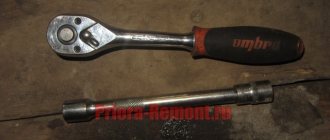
- knob;
- rod compass;
Scheme
The pattern for tightening on a 16-valve engine differs from the pattern for an 8-valve engine, so we will present both one and the other so that you can compare them.
Diagram for 16 valves Diagram for 8 valves
Just don't get confused when you install. In any case, before starting work, check the instructions that came with the car. Tightening with different torques on a 16 valve unit occurs in 2 circles with different torques, and then another 2 circles with a rotation of 90 degrees. Nothing is difficult, which means you can cope on your own.
Stages
In order for self-tightening of bolts to be completed successfully and to last for a long time, a number of simple rules should be followed:
- It is better to use new bolts, since during operation they are under constant tension and lose their properties over time. There is no guarantee that the old bolt will not withstand the stress and will burst.
The length should not be more than 9.5 cm
- It is not advisable to reinstall the gasket, even if it is in reasonable condition.
- Strictly observe torque when tightening.
- The sequence of tightening the bolts should be exactly the same as in the diagram for 16-valve power plants.
- Before installing the cylinder head, carefully inspect all parts for damage and deformation. If any are found, do not ignore them, but be sure to replace them. Often, small breakdowns lead to major damage, and sometimes even to the complete destruction of systems and mechanisms.
- Do not use tools of dubious quality and manufacture. This is especially true for a torque wrench.
- 1st circle - moment 20 N m (2 kgf/m);
- 2nd circle - moment 69.4–85.7 N·m (7.1–8.7 kgf·m);
- 3rd circle - turn the bolts 90 degrees;
- 4th circle - another 90 degree turn.
By following these simple rules, you can guarantee the best tightening and a reliable tight connection.
Place the cylinder head on the block, first making sure that the crankshafts and camshafts are set to the top dead center (TDC) position.
The tightening process itself takes place in 4 circles:
As you can see, everything is simple. If you have any questions, watch the video. In terms of time, this work does not take more than twenty minutes, but it allows you to save a decent amount, which they will charge you at the service station.
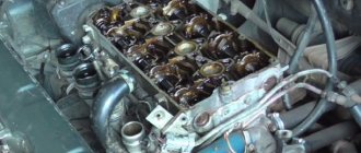
Engine assembly
We wipe the crankshaft journals, cylinder bores and connecting rod bearing seats with a clean rag; by the way, they can also be degreased. We put new liners into the connecting rod and the cover, so that the antennae of the liners fit into the grooves.
Lubricate the bearings, crankshaft journals and cylinders with clean oil. We unfold the piston rings with locks as shown in the figure, the angle between them should be 120 degrees.
We put a mandrel on the piston to compress the rings, having previously lubricated it inside with clean oil. Not forgetting about the direction, the arrow on the piston should be directed towards the front of the engine, we place it in its cylinder.
We turn the crankshaft so that the connecting rod journal is at the very bottom. Gently tapping the wooden handle of a hammer pushes the piston into the cylinder. We remove the mandrel and push the piston down until the connecting rod sits on the crankshaft. We put the connecting rod bearing cap on the bottom, remembering the marks. Tighten the connecting rod cover mounting bolts to a torque of 5 kgf*m. We also repeat with all the other cylinders.
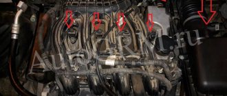
We put back everything that we removed from below. We blow through the top and clean the holes for the cylinder head mounting bolts. We install a new cylinder head gasket and the head itself. Lubricate the bolts with a thin layer of oil, most importantly without fanaticism. We tighten the bolts in several passes in the reverse order of unscrewing, see photo at the beginning of the article. The tightening sequence is as follows:
- first tighten everything with a torque of 2 kgf*m
- then we tighten everything to a torque of 7 – 8 kgf*m
- turn it 90 degrees
- turn it 90 degrees again
We install hydraulic compensators, camshafts and camshaft bearing caps. Lubricate all rubbing surfaces with clean oil. Before installing the camshaft bearing caps, lubricate the perimeter and rims around the spark plug wells with a thin layer of sealant. We tighten the bearing cover bolts in the reverse order of unwinding, with a torque of 2 kgf*m, see photo at the beginning. Well, then we install all the parts in the reverse order of removal. We fill in all the fluids and start it, it may not start right away, this is normal. When you first start it will smoke well until the oil on the cylinders burns, make sure the oil pressure light goes out. Let it run for a minute and turn it off, and suddenly see where something is leaking. We start it several more times, constantly increasing the operating interval, bring it to operating temperature, constantly checking the oil and antifreeze, and also pay attention to the fact that no extraneous noise appears. Let it rest for an hour and then idle again for about an hour, constantly monitoring the temperature. Well, then the break-in, if you sharpened it, if not, then you can drive only the first thousand kilometers, try not to raise the speed above 3000, and not tow it.
Tightening torque for cylinder head VAZ 21126
Many owners of a Lada Priora with engine 21126 16 valves, in the process of servicing and repairing the car, independently replace the head gasket or grind the valves. When performing such work, it is important to observe the sequence and tightening torque of the cylinder head on the Priora. During the operation of any car, including the VAZ 2170 Priora, the engine head is exposed to long-term cyclic effects of gases located in the engine cylinders. On older power units, the tightening of the cylinder head screws could weaken under such loads and periodically needed to be brought to a normal level. Today, all VAZ Priora engines use bolts made of special steel, which are tightened once for their entire service life. If a coolant and oil leak occurs, there is no point in further tightening and tightening these bolts, since this will not improve the tightness of the joint. The only correct way to combat a leak is to remove the head, check the evenness of the mating surfaces and replace the gasket. After performing any repair work related to removing the head from the engine, it must be tightened in compliance with all necessary conditions. Here you also need to know that the tightening sequence on 16 cl and 8 cl units is different, so you need to be careful. The torque on the 16 and 8 valve power units is the same and passes in four circles.
Photo gallery
The photo below shows the procedure for loosening the bolts and tightening them, which must be taken into account when repairing the cylinder head on a VAZ 2170 Priora.
Scheme for loosening bolts on an engine with 8 valves
Scheme for loosening bolts on an engine with 16 valves
16 valve head tightening diagram
8 valve head tightening diagram
Tools and materials
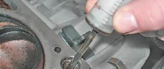
Before starting the tightening procedure, you should prepare everything necessary for the implementation: • a wrench with a built-in dynamometer up to 100 N/?m; • a set of heads and regular keys; • key Togh E14; • caliper for measuring the remaining length of bolts; • plate with a marked scale up to 180 degrees; • new bolts. In order to correctly tighten the cylinder head screws on a VAZ 21126: 1. Remove oil from the mating surfaces and check that there is no liquid in the bolt holes. 2. Install the gasket, center it and place the head on top. 3. Insert 10 mounting screws M10*1.25 into the guide holes, having previously lubricated the threads with engine oil. If you decide to use old bolts, which is permissible for 16 valve heads, then their remaining length should not exceed 98 mm. 4. Perform preliminary pulling according to the scheme with a torque of 12-20 N/m. 5. Increase the tightening degree to 26-34 N/m and re-pass all the bolts in the same sequence. 6. Then you need to tighten the screws 90 degrees, with a force of about 50 N/m. 7. Repeat tightening by 90 degrees again, the torque on the key will be approximately 80 N/m. Some instructions recommend waiting up to 20 minutes between turns, but in practice no advantages of such a scheme have been identified. 8. After assembling the power unit, you should check the quality of the work performed. The procedure for pulling the head on 1.8 liter engines, which are 1.6 liter engines with an enlarged cylinder, is completely identical to that described above. Briefly, 1st - torque 20 N m (2 kgf m); 2nd - torque 69.4–85.7 N m (7.1–8.7 kgf m); 3rd - tighten the bolts 90°; 4th - finally tighten the bolts 90°.
Video “Installing and tightening the cylinder head on a Priora”
The assembly of the upper part of a 16 valve engine is presented in a video from the Expert R channel.
I encountered the following problem: I replaced the piston with a plugless automatic transmission. The diesel is gone. But on a hot engine, a knock appeared, which directly depends on warming up. The feeling is that the block is moving away and the piston-cylinder gap is coming out (during installation I made 3 hundred parts). So the essence of the issue is that there are two tightening methods that I came across in the literature, 1st - a torque of 20 N m (2 kgf m); 2nd - torque 69.4–85.7 N m (7.1–8.7 kgf m); 3rd - tighten the bolts 90°; 4th - finally tighten the bolts 90°. or Using a torque wrench, tighten the head mounting bolts in three steps - first with a torque of 20 N m (2 kgf m), then turn the bolts by 90° and then turn the bolts again by 90°. I pulled the first one myself. Is the question correct? If you have links to sources, please share.
Nuances of work
At different times, Lada Priora cars were equipped with engines with a displacement of 1.6 and 1.8 liters and a different number of valves in the heads - V8 (or 8V) and V16 (or 16V). The type of unit head determines the size of the bolts, the order of their installation and the tightening torque of the cylinder head on the Priora.
If the car has an 8-valve engine, then it can use head mounting bolts of different sizes:
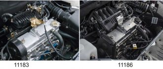
- on old motors 21114, M12*1.25 hex head screws are used;
- on more modern 21116, which went into production approximately in mid-2011, M10*1.25 elements with an asterisk head are installed.
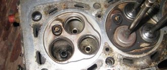
Let's move on to the cylinder block
We remove the pallet. Rotating the crankshaft as it is convenient for us, unscrew two bolts on each connecting rod cap. We use a TORX E10 head for this.
We take out the pistons along with the connecting rods. To do this, use the wooden handle of a hammer to press the connecting rod from below and lightly tap it to knock it up. We remove the old liners and buy new ones of the same size according to the markings on them. Here is another stone in AvtoVAZ’s garden, the owner has never climbed into the car from the interior or into the engine, but three pistons were of group “B” and one was “C”. It turns out that at the factory they re-sharpened one cylinder a little and simply put an enlarged piston there, no words. There are no options, we take group “C”, don’t sharpen the engine because of this. We will not touch the main liners either.
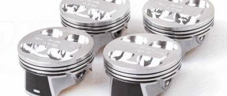
We buy a new piston group that does not bend the valves, connecting rods and connecting rod bearings.
Eliminating longitudinal play of the crankshaft
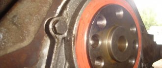
It was noticed on this motor. To eliminate it, replace the thrust half-rings. Standard and repair sizes are available. We take the first repair size, if they are too tight we sand them down a little. We unscrew the middle main bearing and gently push it with a screwdriver and move the half rings. The mark on it is in the form of three serifs, shown below.
When the half ring comes out a little, turn the crankshaft, it will push it out. There are two types of half rings: white at the front and yellow at the rear; the grooves on them should point towards the crankshaft cheeks.
We install them as we removed the new half rings; if they go in with great effort, you can grind them a little on a small abrasive stone, but not from the side of the grooves. Checking the play. We tighten the main bearing with a torque of 8 kgf*m.
Assembling the piston
There is an arrow stamped on the top of the piston; it should be directed towards the front of the engine. And there are marks on the connecting rod that should look the same way. Don't get confused!
We insert one retaining ring into the groove on the piston. We insert the connecting rod into the piston and, having lubricated the connecting rod and the piston pin with oil, insert it into place. Insert the second retaining ring. Although this operation seems simple, it will take some pains. We inspect the assembled structure; all retaining rings must be clearly in their grooves, otherwise a ring that has jumped out while the engine is running can cause a lot of trouble.
After assembly, you need to break off the connecting rod bearing cap, since the connecting rod is made in one piece. It's like that on our cars. First, unscrew the bolts. We insert the connecting rod into the cleats at the level of the mark shown in the figure with the black arrow and lightly clamp it, then break it off with a slight movement of the hand. The first time is very scary. We put the cover in place and tighten the bolts so as not to mix it up in the future.
Checking the thermal gap in the piston rings
We lay out each set of rings for each cylinder. In the future we will not change their places. In turn, we insert each ring into its own cylinder and push it a little with the piston approximately to the middle.
Nominal clearance: 0.25 - 0.45 mm.
The maximum clearance for all is 1 mm. But this already smacks of waste.
Installing new rings
First, install the oil scraper ring expansion spring, then the ring itself. The oil scraper ring lock should face the opposite direction of the spring lock. Then we install the lower compression ring and finally the upper compression ring. The inscription “TOP” must be stamped on the rings; it must face up. The rings in the piston grooves must rotate easily.