In its turn, The axial internal clearance of a double row ball bearing is the amount by which the inner rings move relative to the outer one. In order for the axial clearance to be within the tolerance, the ball bearing (or roller) is adjusted, this is done by correctly tightening the hub nut.
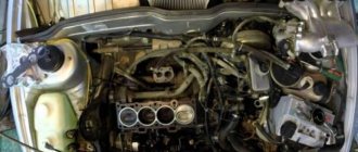
Familiarize yourself with the mounting and arrangement of the bearing with the front hub, as well as with the design of the wheel ball bearing.
The video also shows the process of adjusting the backlash by the locknut tension level:
Step-by-step method for replacing the rear wheel bearing on a VAZ 2109, 2110
- stop the car from the front;
- tear off the central nut (7) of the hub, having first removed the cap (9);
- jack up the side and set the trestles;
- remove the wheel;
- fill the brake drum mounting area with WD-40 or other special liquids (you can use diesel fuel or brake fluid);
- unscrew the guide bolts (it is advisable to lightly tap with a hammer);
- we try to carefully remove the brake drum (if it doesn’t work, we screw the appropriate bolts into a special thread on the brake drum, apply tension and very lightly try to knock it out with a hammer. In most cases, the result will be positive. There are special drum pullers on sale, just in case , if all else fails);
- unscrew the central nut completely (of course, it is possible to unscrew it immediately, and even remove the hub along with the wheel and drum, but then there is a high probability of damage to the brake pads);
- we tighten the hub (if one of the inner races of the bearing remains on the axle, you need to use a puller or just a sharpened chisel to try to move it from its place);
tear off the wheel bolts;
Installing the back cover
and the rear one after changing the seals in them.
We install an oil intake and an emergency oil level sensor.
VAZ 2110 tightening the hub nut
4.2.3. Replacing the hub bearing
The hub is equipped with a double-row ball bearing, which does not require adjustment or lubrication during operation.
If, when swinging the suspended wheel, play or noise appears while driving, the hub bearing may have failed.
If there is increased play in the wheel, loosen the hub nut and check its tightening torque. If the torque is less than required, try tightening the nut to the required torque and lock it. If there is no play, the bearing will be able to work for some more time.
If there are no mandrels, you can use the rings of the old bearing. To press in the wheel bearing, use the appropriately sized mandrels from the kit.
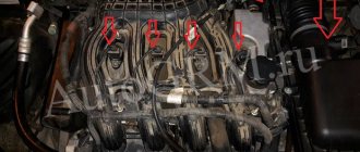
Bolt tightening diagram for GBTSVAZ 2112 16 valves
When performing work, strict tightening rules must be observed. For the 16 valve engine model 2112, the permissible bolt length is 94 mm. If the indicator is 95 millimeters, the parts should be replaced. Some experts even recommend installing new pins for each procedure - this is guaranteed to ensure high-quality operation of the system.
Separately, it is required to adhere to the sequence of tightening the nodes - this guarantees an even fit of the surfaces and the absence of leaks in the future. The last point is the force applied during work. The indicator is critically important, as it ensures tightness and sealing of the block.
How to determine the need for replacement?
Strong noise, humming of the rear hub bearing of VAZ 2109, 2110, “howling” from the rear, increasing when turning, clearly indicates the need to check the condition of the rear hubs. The verification methods are quite simple:
- Be sure to stop the wheel diagonally opposite from the jacking side, and then jack up each rear wheel one by one. (Why each? The fact is that very often there are errors in determining the side of the hum, and even more often there is a need to replace both bearings).
- When the wheel is raised, you need to try to spin it as much as possible. If at the same time you hear extraneous sounds similar to a hum, you don’t have to check further - replacement is necessary.
- if in doubt, you can also check the lateral play of the bearing by grasping the edges of the wheel and rocking it towards you - away from you. If you feel the wheel moving on the axle, the bearing needs to be replaced.
Automotive stores can offer you both a separate bearing and a hub assembly. We see no point in purchasing an assembled unit (except for the cases described below), where replacing the bearing is not at all a difficult matter.
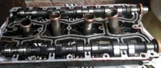
Installing pistons into liners
Once the rings are installed, the pistons can be inserted into the cylinder liners. To do this, tighten the piston rings with a clamp. We install the liner into the lower head of the connecting rod. In such a way that the lock on the liner fits into the recess of the connecting rod head bed. We insert the connecting rods with the piston into the sleeve until the clamp stops. Taking into account the direction of the piston, and with light blows, preferably using a wooden block, we force the piston into the sleeve. By guiding the lower end of the connecting rod into the crankpin of the crankshaft. After the connecting rod rests against the crankshaft with its liner. We install the connecting rod bearing into the connecting rod cover, and put the cover on the studs. In this case, it is imperative to take into account that the liners on the connecting rod and the cover are located in relation to each other, lock to lock.
Step-by-step method for replacing the rear wheel bearing on a VAZ 2109, 2110
- stop the car from the front;
- tear off the wheel bolts;
- tear off the central nut (7) of the hub, having first removed the cap (9);
- jack up the side and set the trestles;
- remove the wheel;
- fill the brake drum mounting area with WD-40 or other special liquids (you can use diesel fuel or brake fluid);
- unscrew the guide bolts (it is advisable to lightly tap with a hammer);
- we try to carefully remove the brake drum (if it doesn’t work, we screw the appropriate bolts into a special thread on the brake drum, apply tension and very lightly try to knock it out with a hammer. In most cases, the result will be positive. There are special drum pullers on sale, just in case , if all else fails);
- unscrew the central nut completely (of course, it is possible to unscrew it immediately, and even remove the hub along with the wheel and drum, but then there is a high probability of damage to the brake pads);
- we tighten the hub (if one of the inner races of the bearing remains on the axle, you need to use a puller or just a sharpened chisel to try to move it from its place);
- inspect the axle for signs of bearing rotation (if there are any, we replace it, it is advisable to replace the hub assembly);
- inspect the brake cylinder for leaks and pads for wear;
- remove the retaining ring from the hub using pliers and/or screwdrivers.
- Be sure to clean the edge from rust, moisten it with WD-40 or whatever you have on hand.
There are three options for pressing out the bearing:
- A special press (not everyone has one).
- A puller (not expensive, can be purchased, will be useful for the future).
- Using a heavy hammer (at least 2 kg) or a sledgehammer. AT first glance, the method may seem a little aggressive, but it is practiced by an overwhelming number of masters and service stations, and we will consider it.
- The hub must be firmly installed on a hard surface, and with several sharp blows through the mandrel, the bearing must be moved from its place. When this happens, you need to install the hub, for example, on a yew tree (so that there is a stop for the hub and free space for the bearing to exit)
- a few more blows and the bearing will come out (don’t rush to throw it away);
- We inspect the seating plane under the bearing, clean off the rust with sandpaper, lubricate it with regular engine oil (you can polish it off);
- the new bearing must be screwed with any suitable bolt through washers (washers must be selected according to the inner races, the bearing is double-row and during installation there is a high probability of its disassembly);
- install the hub on a hard surface.
– we place a twisted bearing on top, and lightly lubricate its mounting plane with oil (a new good bearing usually does not need to be lubricated inside, but if you have doubts and a little experience in assembling and disassembling, you can use Litol -24 lubricant)
– with an ordinary 500-gram hammer, very lightly, we try to align the bearing in the plane;
– take a suitable mandrel (for example, a pry bar), and try to press the bearing in with gentle blows.
-the basic rule is no strong blows, if it doesn’t work, it means it’s crooked
– after the bearing has passed halfway, you can no longer apply much force, since it can no longer warp.
-when we reach the cut of the hub, it is necessary to use the old clip as a mandrel (no strong impacts, the metal is high-carbon, and with a strong impact it can burst and cause very serious injury)
– we push it all the way and install the stopper (if there are problems with installing the stopper, then most likely you did not finish it all the way) the stopper should easily spring into the groove;
Installing piston rings
Now you need to install the piston rings on the piston. As a rule, three rings are installed on one piston. The upper and middle compression and lower oil rings are removable. The rings have an engraving, the inscription should be facing up,
if it is not there, then you can navigate by the chamfer, which is located either along the inner or outer diameter of the piston rings. This chamfer acts as a stiffening rib, which creates resistance to the loads that arise when gases expand in the combustion chamber. If there is a chamfer along the inner diameter, then the ring is placed with the chamfer up, if along the outer diameter, then with the chamfer down. The oil slip rings also have an engraving that should face up; if it is not there, then the direction of the ring does not matter.
The rings on the pistons must be placed in such a way that the ring connectors are not located under each other and do not fall into the groove under the pin. Since, for example, the middle ring connector is located on one side of the piston, the upper and lower ring connectors must be on the other side of the piston, and must be spaced apart from each other, but not fall into the piston pin recess
Assembly
– that’s it, we begin the process of assembling the rear hub bearing on the VAZ 2109, 2110. To do this, we put the hub on the axle (by removing the bolt with which we tightened the cages);
– tighten and tighten the central nut (be sure to install a new one), not forgetting to put the thrust washer;
– put on and screw on the brake drum and wheel;
– check the rotation (there should be no extraneous noise);
– if all is well, lower the car from the jack;
– tighten the wheel and the central nut (the tightening torque of the hub is approximately 20 kgm, this is quite a strong tightening, if you don’t have a torque wrench, you need to use a lever of at least a meter to tighten the nut with a force twice the tightening force of the wheels);
– tighten the hub nut and tighten the wheels.
Non-separable rear wheel hub
On vehicles with one-piece, non-separable units, bearing adjustment is not possible.
You can check the bearing on a “jacked up” wheel.
Cylinder head bolt VAZ 2112 PAYEN turbo M10*1.25 (10 pieces)
- Engine Crankshaft
- Flywheel
- VAZ cylinder head
- Sports camshafts
- Sport timing valves
- Cylinder head components
- Belts | Timing gears
- Gaskets | Oil seals
- Intake system
- Throttle valve
- Clubturbo pistons
- TDMK pistons
- Federal Mogul pistons
- Piston rings
- Connecting rods
- Engine mounts
- Inserts for VAZ engines
- ACL earbuds
- Oil catchers
- Oil crankcase
- Oil pump
- Miscellaneous
Cooling
- Adapters for installing an oil cooler | sensors
Cooling systems for VAZ 2101-2107 16v Cooling radiators Oil radiators Heater radiators Water pumps Fans Thermostats Expansion tanks Miscellaneous Silicone
- Straight pipes
Tubes with flange Tubes with 45 degree rotation Tubes with 90 degree rotation Tubes with 135 degree rotation Hoses Mishimoto Silicone Tubes Silicone Tubes for Cooling System Transmission
- Blocking
Main pair of vases Sports rows of gearboxes Gears 6th transmission of vases Drives of vases Clutch Short-stroke rocker Gearbox sport Rear axle gearbox of vases Spare parts of gearboxes of vases Brake system
- Vacuum booster
Brake master cylinderRear disc brakesBrake discsHand brakesBrake padsFittings for the brake systemFlange washers | transition kitsPedal unitBrake force regulatorCaliper | brake slave cylinderMiscellaneousSuspension
- Clubturbo suspension
Shock AbsorbersSprings Support BearingsTriangle ArmsStretchers | Amplifiers Safety frame Subframes Wheel spacers Steering Anti-roll bars Silent blocks | rubber bushings Silent blocks | polyurethane bushingsStuds | wheel nuts, swivel knuckles, joint heads | Sliding bearingsBall jointsMiscellaneousExhaust system
- Silencers for VAZ
Universal mufflersInsert catalystSpiderDownpipeResonators for VAZUniversal resonatorsBendsPipe | BendsVibration damper (corrugation)FlangesMiscellaneousElectronics
- Ignition system
Turbo timerControl units | WiringInstrumentsAir temperature sensorInnovateBoost controllerAbsolute pressure sensorMiscellaneousFuel system
- Filler necks
Fuel tanks Drain tanks Fuel pressure regulators Fuel rails (ramps) Brackets for fuel pumps Fuel pump Fillers for fuel tanks Fuel injector Fuel filters Hoses Miscellaneous Kits
- Moto kits Turbo
Engine displacement kitsExhaust system kitsE-GAS conversion kitStyling
- Adapters for installing sports steering wheels
Alternative opticsTow hooks | HingesDecorative license platesLocksMirrorsPodiums for instrumentsSeat beltsSteering wheelsGearbox lever capsSport seatsStorage and transportation systemsPedal coversHelmetsFiller capsMiscellaneous4×4Clothing and souvenirs
- Keychains
Vinyl for the car Club card, branded clothing Soft toys | PillowsWindshield stickersPostersMiscellaneousStickersSmartphone casesNailplatesKey lanyardsBody plastic
- Bumpers tuning for VAZ
Air intakesRadiator grillesGlass | Sports upholsteryFenders | Wheel arch extensionsDashboardsDoorsSpoilersLiningsHoodsTrunk lidsMudguardsPlastic body partsAileronsSkirtsMiscellaneousFittings
- Hoses | tubes
Fittings for rubber hosesFittings for Teflon hosesFittings for aluminum tubesCouplings| fittingsAN adapters - Metric threadAN adapters - Inch threadAN adapters - ANAdapters AN - ORBHose fasteningsWelded fittingsThrough the partition fittingsAN TeesPlugsMiscellaneousMiscellaneous
- Thermal insulation
Air filterOils and auto chemicalsToolsWiper bladesPneumohydraulic hood supports
- home
- Catalog
- Engine
- Miscellaneous
- Cylinder head bolt VAZ 2112 PAYEN turbo M10*1.25 (10 pieces)
Cylinder head bolt VAZ 2112 PAYEN turbo M10*1.25 (10 pieces)
PAYEN cylinder head bolts М10*1.25. For the cylinder head of a VAZ 2112. Bolts are used for a higher tightening torque. Installation only requires replacing your standard bolts. Recommended for use when installing turbocharging on a VAZ engine. A special tool is required for installation. Set of 10 pieces.
Specifications:
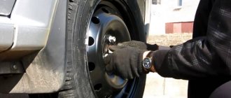
Instructions for self-tightening wheel bearings.
- Place the vehicle in gear or parking brake. Place something under the wheels, such as wheel chocks. This is necessary to prevent the car from flying off the jack.
- Take the balloon from the kit in the trunk (if there is one) and loosen the bolts securing the wheel. The vehicle must not be raised.
- Prepare a place to install the jack (from the kit). It should be firm and even. You can place boards under the jack if necessary. Raise the wheel until it no longer touches the ground. Place a block of wood under the lever just in case. Suddenly the jack is unreliable.
- Unscrew the bolts completely and remove the wheel.
Removing the hub cap
Unscrew the old nut
You need to tighten the nut
Fill the cap with new lubricant and reinstall. Remember that if the wheel bearings are adjusted incorrectly, the wheel alignment changes, as a result of which the vehicle's handling deteriorates, fuel consumption increases, and tires wear out quickly and unevenly.
The described process can be clearly seen in the following video: Do not forget to periodically check the bearings. This ensures your safety on the roads. Best regards, PodshipnikTsentr.RU team
Adjustment
Checking its functionality and adjusting it is carried out as follows:
- Raise the front wheel using a jack;
- Remove the wheel;
- Using a chisel, remove the protective cap on the front hub bearing;
- Remove the brake pads;
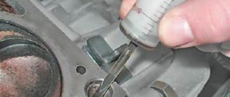
- The indicator holder should be secured to the steering knuckle;
- Place the leg of this indicator against the hub, as close as possible to the adjusting nut;
- Rings of spanners are placed on the studs and the nuts are tightened. While holding them, the hub rotates and moves in the axial direction;
- Using the indicator, the movement or gap indicator is determined. If it is more than 0.15 millimeters, the gap must be adjusted;
- Reinstall the wheel without using the protective cap. Secure it with two bolts screwed in diametrically;
- Using a chisel, straighten the flange on the bearing nut and remove the nut with a 27mm (socket) wrench;
- Using a torque of 2.0 kg-cm, tighten the new adjusting nut;
- Loosen the nut, then tighten it again, but now with a torque of 0.7;
- Slowly release the adjusting nut 25 degrees and turn the wheel in a vertical plane. There should be a slight play;
- Check the gap. Its indicators should be in the range from 0.08 to 0.02 millimeters;
- In this position, lock the nut with the collar caulked in special grooves. They are located on the steering knuckle at the end of its axle;
- Remove old grease from the protective cap and apply new one. About 25 grams. Experts recommend using Litol 24, although there are worthy alternatives;
- Install the protective cap on the bearing;
- The wheel is installed in its rightful place.
Such diagnostics with repair elements will extend the life of your wheel bearing. If the adjustment does not allow the gap to return to the required parameters, the bearing should be completely replaced.
VAZ 2110 tightening the hub nut
06/02/2018 admin Comments No comments
How to tighten the hub nut and to what torque Useful articles and instructions
The front wheel bearing torque is the force with which the hub nut is tightened. Units of measurement – N*M (or kgf*m). The front bearings have internal axial clearance, which is necessary for proper operation of the bearing, namely:
- preventing angular displacement of rings;
- reduction of friction of rolling elements and raceways;
- correct distribution of internal stresses on separators and cages.
- compensation of thermal expansion.
- increasing the contact angle for axial loads.
In turn, the axial internal clearance of a double-row ball bearing is the amount by which the inner rings move relative to the outer one. In order for the axial clearance to be within the tolerance, the ball bearing (or roller) is adjusted, this is done by correctly tightening the hub nut. Familiarize yourself with the mounting and arrangement of the bearing with the front hub, as well as with the design of the wheel ball bearing.
The video shows the process of adjusting the backlash by the locknut tension level:
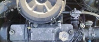
Preparing for repairs
When replacing a VAZ-2110 wheel bearing, you need to install the car as level as possible. Place wheel chocks under the rear wheels, which can even be used as ordinary bricks. You will need to remove the front wheels. It is better to carry out repairs first on the left side, then on the right side. In addition, you need to get a 30mm socket or socket wrench. Only with its help will you be able to unscrew the hub nut.
It is advisable that this wrench have a large lever, because the tightening torque of the connection is very large. Please note that you will need to loosen the nut. To do this, you can use a small drift and hammer. A couple of light blows and the nut will be released. It is worth noting that replacing the rear wheel bearing of a VAZ-2110 is carried out in almost the same way. Only a slightly different puller is used.
How hard should you tighten the wheel nut on your car?
For each car, torque standards are established, since the tightening force for the locknut depends on the following factors: - Bearing dimensions; — Regulated axial clearance; — Diameter and thread pitch; The following are the force indicators for properly tightening the nut. The database will be gradually replenished.
If you have not found the tightening torque values for your car (Skoda Octavia, Subaru models, Toyota Corolla), find the bearing you have installed and the same thread diameter or ask a question in the comments.
Tightening torques for the front wheel bearing on a VAZ (LADA)
Tightening torques for the front wheel bearing on Ford
Tightening torques for the front wheel bearing on a Chevrolet
Tightening torques for the front wheel bearing for Renault
Tightening torques for the front wheel bearing on Daewoo
Tightening torques for the front wheel bearing on Opel
How to tighten the hub nut to the correct torque
To tighten threaded connections, where it is recommended to maintain a certain torque, use special torque wrenches . Inside the tool there is a dynamometer with a scale or a special device with a limiter, which is activated when the required tightening force is reached. Keys also come with value intervals, for example 5-25 (minimum 5 N•m, maximum 25 N•m). The threaded connection is tightened until the arrow shows the required value or the limiter operates. There are also expensive and exact analogues - with an electronic display, but for the operation and repair of passenger cars a mechanical version is suitable.
The photo shows the main types of such keys.
- With preset torque, not adjustable.
- With preset torque value, adjustable.
- With tightening force indicator.
- With digital display of applied torque.
Watch the video on how to use a torque tool:
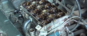
Installation and dismantling procedure
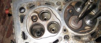
The part called the cylinder head is attached to the cylinder block with 10 screws. They are unscrewed with a 10mm socket wrench. The procedure for dismantling the cylinder head is shown in the first photo.
Reversal sequence (1-10)
The standard screw length is 9 3 mm. If the screw has been pulled out to at least 95 mm, it is replaced with a new one (AvtoVAZ requirement).
During installation, a different scheme is used (photo 2). Each screw is lubricated with machine oil, otherwise the efforts will be reduced to nothing.
How to tighten a hub nut without a torque wrench
Many car enthusiasts, when repairing their car, consider it not advisable to purchase torque wrenches or other specialized devices (pullers, etc.). There is a good way to tighten the fastener to the required torque without using a torque gauge. The following devices will be required: 1. Ratchet with a head for a lock nut; 2. Pipe for extending the ratchet to create the required “shoulder”; 3. Roulette; 4. Marker; 5. A weight that can be hung on the “shoulder” (for example, a 32 kg weight).
The essence of the method is to calculate the moment using the formula from elementary physics classes:
P is the applied force, N; l is the distance from the hub to the point of application of force - the “shoulder”, m. The ready-made formula for our case will be as follows:
P1 = (M2•100)/(M1•10) ( • 10 (or • 9.8) - translated into Newtons), where
P1 is the distance at which the sinker is attached to the “shoulder” relative to the torsion point, cm; M1—cargo mass, kg; M2—required torque, N•m.