By following these simple rules, you can guarantee the best tightening and a reliable tight connection.
Place the cylinder head on the block, first making sure that the crankshafts and camshafts are set to the top dead center (TDC) position.
Proper twisting
The tightening process itself takes place in 4 circles:
- 1st circle - moment 20 N m (2 kgf/m);
2nd circle - moment 69.4–85.7 N·m (7.1–8.7 kgf·m);
As you can see, everything is simple. If you have any questions, watch the video. In terms of time, this work does not take more than twenty minutes, but it allows you to save a decent amount, which they will charge you at the service station.
In what cases is it necessary to tighten the block?
During the operation of any car, including the VAZ 2170 Priora, the engine head is exposed to long-term cyclic effects of gases located in the engine cylinders. On older power units, the tightening of the cylinder head screws could weaken under such loads and periodically needed to be brought to a normal level. Today, all VAZ Priora engines use bolts made of special steel, which are tightened once for their entire service life.
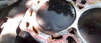
If a coolant and oil leak occurs, there is no point in further tightening and tightening these bolts, since this will not improve the tightness of the joint. The only correct way to combat a leak is to remove the head, check the evenness of the mating surfaces and replace the gasket. After performing any repair work related to removing the head from the engine, it must be tightened in compliance with all necessary conditions.
The video from the author Alex ZW shows the process of installing the cylinder head on an 8-valve engine.
Let's start to disassemble
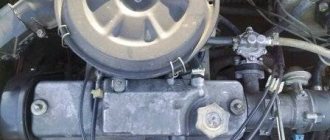
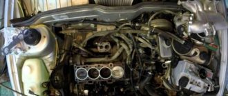
First drain the oil and antifreeze. We remove the protective cover, the air filter with hoses, and disconnect the connectors of the ignition coils, throttle cable and throttle assembly.
We remove the thermostat housing and at the same time disconnect all the connectors and hoses connecting them. We remove all the cables that were in our way towards the battery.
We remove the generator. We unscrew eight of the thirteen nuts holding the intake manifold and remove it. We unscrew all the bolts securing the valve cover, as well as the side engine support.
Unscrew the eight nuts and remove the exhaust manifold.
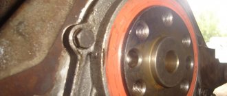
Remove the timing belt, camshaft pulleys and pump.
In three steps, so as not to deform the part, we first loosen and then unscrew twenty bolts of the camshaft bearing housing, head eight. Be sure to follow the sequence shown in the photo.
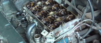
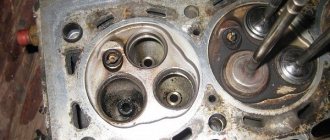
Remove the bearing housing. After removing the camshafts, there is a noticeable lip left on the intake camshaft.
Also, in several steps, we first loosen and then unscrew the ten head bolts. Be sure to follow the sequence shown in the photo.
Remove the cylinder head. All sixteen valves have been replaced.
Nuances of work
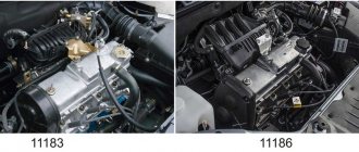
At different times, Lada Priora cars were equipped with engines with a displacement of 1.6 and 1.8 liters and a different number of valves in the heads - V8 (or 8V) and V16 (or 16V). The type of unit head determines the size of the bolts, the order of their installation and the tightening torque of the cylinder head on the Priora.
If the car has an 8-valve engine, then it can use head mounting bolts of different sizes:
- on old motors 21114, M12*1.25 hex head screws are used;
- on more modern 21116, which went into production approximately in mid-2011, M10*1.25 elements with an asterisk head are installed.
When installing a removed head, it is necessary to use new screws, since the old ones will be stretched and have internal damage.
Also, the engines use gaskets of different designs - combined on the old unit and all-iron on the new one. The procedure for tightening bolts for engines with metal and combined gaskets is absolutely identical.
The main nuances when performing work are checking the length of the fasteners, observing the sequence of tightening the screws and monitoring the tightening force. Violation of these conditions leads to damage to parts and the need for additional repair work. The procedure itself is not complicated and can be done independently in any convenient place - in a garage or in an open parking lot, with the exception of the case of installing the head on the engine, which is preferably installed indoors.
It is important to remember that tightening the bolts “by eye” without a torque wrench is unacceptable, since a uniform fit of the mating surfaces of the head and block will not be ensured.
Tools and materials
Before starting the tightening procedure, you should prepare everything necessary to perform:
- wrench with built-in dynamometer up to 100 H⋅m;
- a set of sockets and regular keys;
- Togh E14 key;
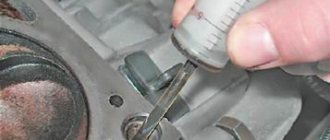
- calipers for measuring the remaining length of bolts;
- plate with a marked scale up to 180 degrees;
- new bolts.
A torque wrench is an important tool for DIY repairs.
Step-by-step instruction
Sequence of operation on an 8 valve engine:
- Wipe the cylinder head surfaces and dry the bolt holes in the engine block.
- Install the gasket on the block and align it along the guides.
- Mount the head on top and insert 10 M10 or M12 mounting bolts. If the owner decides to save money and keep the old screws, then they should have a length of no more than 135.5 mm.
- Tighten the elements according to the diagram. The tightening force should not exceed 20 N⋅m.
- Then you need to re-tighten the bolts. The second tightening force should be in the range from 70 to 85 N⋅m.
- Next, you need to tighten the screws by 90 degrees in the same sequence. The rotation angle can be controlled using a special device, which is a plate with an attached scale from 0 to 180 degrees.
- In accordance with the regulations, you need to tighten the bolts again by 90 degrees.
- The attachment of the 8 valve head to the block is complete.
- After assembling the motor, you need to check the quality of operation by starting and warming up the engine. A securely tightened joint between the head and the block should not allow working fluids to leak from the crankcase of the power unit.
Video “How to properly tighten cylinder head bolts”
In this video, a master with extensive experience shows and describes in detail how to properly tighten the cylinder head bolts. On a Lada Priora car with a 16-cl unit, work is performed according to the same scheme.
Tools:
- Open-end wrench 10 mm
- Open-end wrench 13 mm
- Open-end wrench 17 mm
- 13 mm straight box spanner
- 15 mm straight box spanner
- Driver for socket attachment
- 17mm wrench attachment
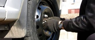
- Screw jack
- Wheel key
- Medium flat screwdriver
- Medium Phillips screwdriver
- 5 mm hex key
- Ratchet wrench
- Extension
- 8 mm head
- 10 mm head
- 13 mm head
- 16 mm high socket or spark plug wrench
- Torx E8 head
- Torx head E14
- Funnel
- Torque wrench
- Special wrench for turning the tension roller (or circlip remover)
- Camshaft pulley locking key
- Knife (or scraper)
- Calipers
- Valve adjustment tool
- Tweezers
- Micrometer
Parts and consumables:
- Shoe – 2 pcs.
- Coolant 8 l
- Cylinder head gasket
- Cylinder head bolt kit
- Technical capacity
- Throttle body gasket (if necessary)
- Sealant-gasket type LOCTITE 5910
- Sealant type LOCTITE 574
- Solvent type 646
- Shims (if necessary)
- Rags
2. Reduce the pressure in the engine power supply system if work is performed immediately after a trip.
3. Disconnect the wire from the negative terminal of the battery.
7. Remove the ignition coils and remove the spark plugs as described here.
8. Disconnect the wire connectors from the emergency oil pressure drop sensor (see here), the phase sensor (see here) and the coolant temperature indicator sensor, which is located under the thermostat (see photo below).
9. Loosen the clamps and disconnect the five cooling system hoses from the thermostat pipes.
10. Disconnect the wire connector from the DTOZH sensor on the thermostat (engine management system) as described here.
11. Unscrew the nut securing the end of the “mass” wire and remove the wire.
12. Remove the intake manifold as described here.
13. Unscrew the screw of the pressure plate of the bracket securing the fuel line to the cylinder head and remove the plate.
14. Remove the mounting bolt and disconnect the earth wire from the cylinder head.
15. Remove the engine cylinder head cover. How to do this, see here.
16. Unscrew the 5 fastening bolts and remove the upper front protective cover of the timing belt (gas distribution mechanism).
17. Remove the 2 bolts securing the lower front timing belt cover (timing belt) and remove the timing cover.
18. Loosen the tension roller bolt and remove the timing belt from the camshaft pulleys.
19. While holding the camshaft pulleys from turning, unscrew the bolts securing the camshaft pulleys and remove the pulleys.
Note:
To prevent the camshafts from turning when removing the bolts securing the camshaft toothed pulleys, we recommend using one of the devices shown in the photo.
20. Remove the keys from the grooves of the camshaft shanks.
Video “Installing and tightening the cylinder head on a Priora”
The assembly of the upper part of a 16 valve engine is presented in a video from the Expert R channel.
I encountered the following problem: I replaced the piston with a plugless automatic transmission. The diesel is gone. But on a hot engine, a knock appeared, which directly depends on warming up. The feeling is that the block is moving away and the piston-cylinder gap is coming out (during installation I made 3 hundred parts). So the essence of the issue is that there are two tightening methods that I came across in the literature, 1st - a torque of 20 N m (2 kgf m); 2nd - torque 69.4–85.7 N m (7.1–8.7 kgf m); 3rd - tighten the bolts 90°; 4th - finally tighten the bolts 90°. or Using a torque wrench, tighten the head mounting bolts in three steps - first with a torque of 20 N m (2 kgf m), then turn the bolts by 90° and then turn the bolts again by 90°. I pulled the first one myself. Is the question correct? If you have links to sources, please share.
Torque wrench and its types
It is needed to tighten the cylinder head bolts. In 2022, devices are divided into three main types.
Snap key
A fairly popular type of device, widely used due to its moderate cost and ease of operation.
The principle of operation is based on setting the required torque on the main and auxiliary scales. When the set force is reached, the ratchet and key are activated and slip with a characteristic sound.
Arrow key
The very first and simplest variety, preserved from USSR times in many workshops. The operating principle is based on the resistance of the torsion bar when the torque increases.
The main disadvantage is the low accuracy of the device - over time, the torsion bar wears out and the key begins to lie in a larger direction.
Digital key
Digital devices are characterized by increased measurement accuracy, which allows them to be used on advanced internal combustion engines that require careful calibration.
Such keys are still rare in 2022 and are found mainly in workshops, due to their high cost.
Other devices
In the absence of a special tool, you can use improvised materials such as a long lever and a regular cantor. The point is to calculate the standard formula.
For example, to obtain a tightening torque of 10 Nm, you should use a 1 meter long lever and apply a force of 1 kg to its end.
Engine assembly
We wipe the crankshaft pins, cylinder mirror and connecting rod bearing seats with a clean rag; by the way, you can degrease them. We insert new liners into the connecting rod and cover so that the antennae of the liners fit into the grooves.
Lubricate the liners, crankshaft pins and cylinders with clean oil. We open the elastic bands in blocks as shown in the figure, the angle between them should be 120 degrees.
We put a mandrel on the piston to compress the rings, having previously lubricated it from the inside with clean oil. Not forgetting the direction, the arrow on the piston should be directed towards the front of the engine, insert it into our cylinder.
Turn the crankshaft so that the connecting rod is at the bottom. Lightly tap the wooden handle of the hammer to press the piston into the cylinder. Remove the spindle and push the piston until the connecting rod rests on the crankshaft. Place the connecting rod bearing cap on the bottom, remembering the marks. Tighten the connecting rod cover bolts to a torque of 5 kgf * m. We repeat the same with all other cylinders.
We put back everything that was removed from below. We blow air from above and clean the holes for the head bolts. We install a new head gasket and the head itself. Lubricate the bolts with a thin layer of oil, most importantly without fanaticism. We tighten the bolts in several stages in the reverse order of unscrewing, see the photo at the beginning of the article. The tightening sequence is as follows:
- first we tighten everything with a torque of 2 kgf * m
- then tighten everything with a torque of 7-8 kgf * m
- rotate 90 degrees
- rotate 90 degrees again
We install hydraulic lifters, camshafts and camshaft bearing cover. All rubbing surfaces are lubricated with clean oil. Before installing the camshaft bearing cap, lubricate the perimeter and rims around the spark plug wells with a thin layer of sealant. Tighten the bearing cover bolts in the reverse order of unwinding, with a torque of 2 kgf * m, see photo at the beginning. Well, let's install all the parts in the reverse order of removal. Fill in all the fluids and let's get started, it may not start right away, this is normal. At the first start it will smoke well until the oil on the cylinders runs out, we see that the oil pressure light goes out. Let it work for a minute and turn it off, suddenly we look where something has flowed. We turn it on several times, constantly increasing the operating range, bringing it to operating temperature, constantly checking the oil and antifreeze, and also pay attention to ensure that there are no extraneous noises. Let it rest for an hour and then idle again for about an hour, constantly monitoring the temperature. Well, if the break-in is abrupt, if not, you can only drive the first thousand kilometers, try not to increase the speed beyond 3000 and not tow.
Photo gallery
The photo below shows the procedure for loosening the bolts and tightening them, which must be taken into account when repairing the cylinder head on a VAZ 2170 Priora.
Scheme for loosening bolts on an engine with 8 valves
Scheme for loosening bolts on an engine with 16 valves
16 valve head tightening diagram
8 valve head tightening diagram