If you have some experience, troubleshooting in the injection engine system of a car can be done “manually”, that is, using a multimeter and based on your own observations of the behavior of the motor.
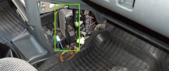
But performing this task is greatly facilitated by searching for faults and errors in the memory of the ECU (controller), for which purpose a diagnostic connector is installed on cars, including the VAZ 21099.
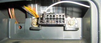
It is attached to the bottom of the shelf under the glove compartment, next to the additional relay and fuse box:
Description of the Autocom program
List of supported ECUs:
- engine diagnostics using the OBD2 protocol - engine diagnostics using factory protocols - diagnostics of electronic ignition systems - diagnostics of climate control systems - diagnostics of immobilizers - diagnostics of transmission control systems - diagnostics of ABS systems - diagnostics of SRS Airbag systems - diagnostics of the dashboard and resetting service intervals - diagnostics of systems ensuring comfort - diagnostics of body electronics systems
The GENERIC diagnostic program is a standards-based diagnostic program specifically designed to link and standardize fault codes. GENERIC is included for car and truck variants.
Protocols and standards 2xHS CAN (ISO 11898-2), SW CAN (SAE J2411), K/L (ISO 9141-2), VPW (J1850), PWM (J1850), RS485 (J1708), TTL and (SPI, analog in, 5volt out).
With the onboard recorder feature, you can record parameters in real time while the vehicle is moving. While recording, you can, with the press of a button, highlight and remember a specific error for the purpose of studying it later. TCS CDP is equipped with built-in memory, eliminating the need for a computer. Memory is not included.
Useful: Pinout of diagnostic connector for VAZ cars
With the Autocom multi-color indicator, you have complete control over the diagnostic process. Different colors and sound prompts will indicate to you which diagnostic stage is currently running. For example, if the indicator switches between blue and green, it communicates with the vehicle's control unit.
When Autocom is connected to a vehicle, the device will check the vehicle's onboard voltage and automatically adjust to the vehicle's 12 or 24 volt voltage level. If the voltage gets too high or too low, Autocom will alert you with both an audible prompt and an indicator light, as well as an alert via the battery icon in the software.
The software has a feature that allows you to read the chassis number from the vehicle you would like to diagnose. This ensures that the model and year are selected automatically. In addition, the engine code for vehicles that are usually available for reading is also automatically selected.
The Intelligent Scanning System (ISS) scans all the systems in the vehicle and displays the fault codes that are stored in each system. This saves time and gives you a quick overview of the current condition of the vehicle as a whole. Once the ISS is completed, you can select a dedicated management system to analyze the results further.
Intelligent System Identification (ISI) detects and automatically selects the type of controller that is installed in the vehicle. This ensures that the diagnostic session is completed correctly with the correct parameters as required.
According to this feature, you will be able to see the adaptations and adjustments that are possible for a particular vehicle without having the vehicle near you. Together, using the texts as a guide, you can plan and be effective in your work, even in difficult situations.
The Autocom car scanner is equipped with a unique multiplexer technology, which allows it to be used on all types of vehicles, regardless of voltage level and communication standards. For those vehicles that do not use a standard 16-pin connector, it is possible to connect special adapter cables.
Diagnostic modes, OBD protocols for VAZ cars
The OBD standard has five types of information exchange protocols:
- CAN type;
- KWP2000;
- ISO 9141 version 2;
- J1850 VPW and PWM.
The purpose of OBD is to harmonize the various electronic systems of the car and ensure the exchange of information between devices. The standard establishes a number of rules for the transmission of data packets. The exchange speed is individual for each protocol. The ELM327 adapter coordinates the ECU and external devices for reading information. The data is displayed to the user in an accessible form.
The fastest is the CAN bus. The latest Zhiguli models provide for the use of this standard. Other protocols on this family:
- ISO 9141;
- K, L lines;
- K, L lines (extended block 55 pins).
Note: the number of supported diagnostic and interrogation modes of on-board systems depends on the installed protocol. The owner needs to check the year of manufacture and model of the standard control unit before servicing. The more recent the ECU and its firmware, the wider the list of available scanning parameters.
Important:
Some ECUs do not support the full set of functions without the use of a dealer scanner.
Select the car model and year of manufacture to determine which diagnostic modes your car supports through the ELM327 adapter, as well as what protocol the OBD2 port is based on. The data is presented for the following VAZ models and their modifications: 2114, 2107, 2110, 2112, 2109, 2115, 2106, 2108 and others.
Note:
(1) — The numbers between brackets (x3) correspond to the number of vehicles of the same type
(2) - DIN horsepower (multiplied by 0.736 for kW power)
(3) - PID is only supported for the primary oxygen sensor (#1)
- Mode X Column: A vehicle showing 00000000 in a mode means that the corresponding PID is not active and that as a result the mode is maintained but does not respond to any requests. None of the vehicles described below support Mode 8.
- Energy column: fuel type, Die for diesel, Pet for gasoline, Hyb for hybrid
- The vehicles on this list are classified alphabetically by make, model, then in order of increasing horsepower.
Mode 1
This mode returns common values for some sensors, such as:
- engine speed;
- vehicle speed;
- engine temperature (air, coolant);
- information about oxygen sensors and air-fuel mixture.
Mode 2
This mode provides a freeze frame (or instantaneous) failure data. When the ECM detects a malfunction, it records sensor data at the specific point in time when the malfunction occurs.
Mode 3
This mode displays stored diagnostic trouble codes. These fault codes are standard for all car brands and are divided into 4 categories:
P0xxx: for standard transmission related faults (engine and transmission) C0xxx: for standard chassis faults B0xxx: for standard body faults U0xxx: for standard communication network faults
More detailed information and definitions of common trouble codes are available on the OBD Common Trouble Codes page.
Mode 4
This mode is used to clear stored trouble codes and turn off the engine malfunction indicator.
Note: There is generally no need to repair a problem that has not been diagnosed or corrected. The MIL will illuminate again during the next driving cycle.
Mode 5
This mode provides the results of self-diagnosis performed on the oxygen/lamda sensors. This mainly applies only to gasoline vehicles. For new ECUs using CAN, this mode is no longer used. Mode 6 replaces features that were available in Mode 5.
Mode 6
This mode provides self-diagnosis results performed on systems that are not subject to constant monitoring.
Mode 7
This mode produces unconfirmed fault codes. After repair, it is very useful to check that the fault code does not appear again, without having to perform a lengthy test run. The codes used are identical to those in mode 3.
Mode 8
This mode provides self-diagnosis results on other systems. It is unlikely to be used in Europe.
Mode 9
This mode gives vehicle information such as:
- VIN (vehicle identification number)
- calibration values
Mode 10 (or Mode A)
This mode gives permanent error codes. The codes used are identical to those in modes 3 and 7. Unlike modes 3 and 7, these codes cannot be cleared using mode 4. Only a few road cycles without the problem occurring can clear the fault.
If you have some experience, troubleshooting in the injection engine system of a car can be done “manually”, that is, using a multimeter and based on your own observations of the behavior of the motor.
But performing this task is greatly facilitated by searching for faults and errors in the memory of the ECU (controller), for which purpose a diagnostic connector is installed on cars, including the VAZ 21099.
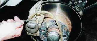
It is attached to the bottom of the shelf under the glove compartment, next to the additional relay and fuse box:
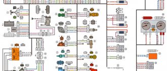
Depending on the operating protocol, pinout options are allowed:
When using the standard ISO 9141-2 protocol, it is activated via pin 7, while pins 2 and 10 in the connector are inactive. For data transmission, pins numbered 4, 5, 7 and 16 are used (sometimes pin number 15 can be used).
Error code: IC-327 Diagnostic adapter ELM327 BT Android / IOS iCartool IC-327 buy on the website AvtoSkanery.RU - Avtoskanery.RU
With a protocol like SAE J1850 in the VPW (Variable Pulse Width Modulation) version, pins 2, 4, 5, and 16 are used. The connector is typical for American and European General Motors cars.
Using J1850 in PWM (Pulse Width Modulation) mode provides additional use of pin 10. This type of connector is used on Ford products. The J1850 protocol in any form is characterized by the non-use of pin number 7. Start of form
Of course, for many, such diagrams and descriptions of OBD2 connector pinouts are very complex and unnatural. Often, motorists prefer to periodically take their car to a specialized car service center and not even think about diagnostic connectors and, especially, about their pinouts.
But it is still worth recognizing the usefulness of self-diagnosis. Experienced motorists say that it is necessary for every car owner to have a diagnostic scanner in their car to quickly check their doubts about the operation of the car, check for errors, settings and the like, which, first of all, will save significant money.
Obvious advantages of self-diagnosis via the OBD2 connector:
- Saving money, service stations charge a lot of money for simple computer diagnostics
- To promptly find out the error and understand the malfunction without the help of specialists, you don’t need to be nervous at the service station and you can avoid imaginary breakdowns, as often happens in unscrupulous services.
Good luck on your journey and in diagnosing your car!
Part 1 -1998-99 PCM Connector Pinout Diagrams (GM 4.3L, 5.0L, 5.7L)
August 18, 2012 Updated: July 14, 2020 Author: Abraham Torres-Arredondo Article ID: 205
PCM Connector: Blue (C1) 1998-99
In this article you will find a description of the 4 PCM connector pinouts for 1998-1999 GM 4. 3L, 5.0 or 5.7L engines.
NOTE: For other PCM pin diagrams, please note the following:
- 1993 PCM Pinout (GM 4.3L, 5.0L, 5.7L GAS w/4L60-E) .
- 1994 PCM pinout (GM 4.3L, 5.0L, 5.7L GAS with automatic transmission) .
- PCM 1995 pinout (GM 4.3L, 5.0L, 5.7L GAS with automatic transmission) .
- 1996-97 PCM Connector Pinout Diagram (GM 4.3L, 5.0L, 5.7L) .
Each connector can be identified as:
- C1 Blue (32-pin connector).
- C2 Red (32-pin connector).
- C3 Clear -or Grey- (32-pin connector).
- C4 Black (24-pin connector).
The symbol: means the connector pin # will have one of two different wires DEPENDING on the year of your vehicle or whether it is equipped with 4.3L, 5.0L, 5.7L, etc.
9019 4 Yellow with black stripe Violet with white stripe
| C1 (blue) 32-pin PCM connector | |||
| Pin | Wire color | Description | |
| 1 | — | Empty | |
| 2 | — | Empty | |
| 3 | Brown with white stripe | 1X Cam (CMP) Sensor Signal 8 | |
| — | Empty | ||
| 5 | — | Empty | |
| 6 | — | Empty | |
| 7 | Low fuel level sensor | HO2 sensor 1 | |
| 8 | Pink with black stripe | Cam sensor ground (CMP) (low) | |
| 9 | Violet | Fuel level sensor (fuel level output) | |
| 10 | — | Empty (1998 only) | |
| 10 | Yellow-brown with black stripe | TCC Control Solenoid (1999 only) | |
| 11 | — | Empty | |
| 12 | — | Empty | |
| 13 | — | Empty | |
| 14 | Brown | AIR Relay Control (California only) | 15194 |
| Vehicle Speed Sensor (VSS) | |||
| 16 | — | Empty | |
| 17 | — | Empty | |
| 18 | Dual tank fuel module (1998 only) | ||
| 18 | — | Empty (1999 only) | |
| 19 | Purple with white stripe | HO2S High Bank 1 Sensor 1 | |
| 20 | Purple | HO2S High Bank 1 Sensor 2 (1998 only) | |
| 20 | Purple | HO2S H High Bank 2, Sensor 2 without C6P - up to 8600 GVW (1999 only) | |
| 20 | Violet | HO2S High Bank 1, Sensor 2 with C6P - over 8600 GVW (1999 only) | |
| 21 | Violet | HO2S High Bank 2 Sensor 1 | |
| 22 | Purple with white stripe | HO2S High Bank 2 Sensor 2 (1998 only) | |
| 22 | Purple with white stripe | HO2S High Bank 2 Sensor 2 w/C6P - over 8600 GVW (1999 only) | |
| 22 | Purple with white stripe | HO2S High Bank 1 Sensor 2 with C6P - Below 8600 GVW (1999 only) | |
| 23 | — | Empty | |
| 24 | Tan | HO2S Low Bank 1 Sensor 2 (1998 Only) | |
| 24 | Yellow-brown | HO2S Bank 2 Sensor 2 without C6P - up to 8600 GVW (1999 only) | |
| 24 | Tan | HO2S Low Bank 1 Sensor 2 w/C6P-over 8600 GVW (1999 only) | |
| 25 | Yellow-brown with white stripe | HO2S Low Bank 1 Sensor 1 | |
| 26 | Tan with white stripe | HO2S Low Bank 2 Sensor 2 (1998 only) | |
| 26 | Yellow-brown with white stripe | HO2S Low Bank 2 Sensor 2 w/C6P - over 8600 GVW (1999 only) | |
| 26 | Tan w/White stripe | HO2S Low Bank 1 Sensor 2 without C6P - up to 8600 GVW (1999 only) | |
| 27 | — | Empty | |
| 28 | Violet | Crank sensor (CKP) Ground (low) | |
| 29 | Light green with black | Vehicle Speed Sensor (VSS) Low | |
| 30 | Purple with white stripe | Vehicle Speed Sensor (VSS) Signal | |
| 31 | Yellow | 4X Crank (CKP) Sensor Signal 32 | |
| — | Empty | ||
Precautionary measures
Here are some very important precautions when checking the wires coming out of the PCM connectors.
- If one or any of the wires on your GM vehicle do NOT match the color shown in the pinout diagrams, you should not use the pinout diagrams in this article. For what? Because this is a clear indication that this is NOT the connector pin chart for your specific vehicle.
- Never touch the front of the connector. You should use a punch to pierce the wire and examine the wire a few inches from the connector. To see what this tool looks like: Wire Piercing Probe .
Disclaimer
I've spent many hours double, triple and quadruple checking these pin charts (on this page and the next few pages) using the best sources to compile it, but nothing in life is perfect. I don't have a staff of proofreaders or editors (or even volunteers ), I'm just a little guy typing these things in my spare time to help and give back to the Do-It-Yourself community. So, without further ado, here is my disclaimer:
© Copyright Abraham Torres-Arredondo : This information is distributed in the hope that it will be useful, but WITHOUT ANY WARRANTY; without even the implied warranty of MERCHANTABILITY or FITNESS FOR A PARTICULAR PURPOSE.
If you find any errors, please let me know. You can use the contact form at the end of the article.
Types of connectors with obd2 pinout
In the early 2000s, there were no strict requirements for the outer shape of the connector, and many automakers assigned the device configuration themselves. Today, there are two types of OBD 2 connector, designated as Type A and Type B.
Both plugs are almost identical in appearance and have a 16-pin output (two rows of eight contacts), the only difference is between the central guide grooves.
The pins in the block are numbered from left to right, with contacts numbered 1-8 in the top row, and numbers 9 through 16 in the bottom row. The outer part of the housing is made in the shape of a trapezoid with rounded corners, which ensures reliable connection of the diagnostic adapter. The photo shows both versions of the devices.
Connector types - Type A on the left and Type B on the right
OBD 2 connector – pinout
connector pinout keyboard mouse monitor PC pinout communication protocol SUN MAC
TX5 - TXC-
| 9019 9019 9019 BLUE VGA cables extend VGA monitor length up to 100 feet with high resolution up to 1920x1200. See more details. PS/2 CABLES .
9019 LD191 LD191 9039 90I Open 9039 Mating face MDR36 internal thread NC NC
9039 2 | ||||||||||||||||||||||||||||||||||||||||||||||||||||||||||||||||||||||||||||||||||||||||||||||||||||||||||||||||||||||||||||||||||||||||||||||||||||||||||||||||||||||||
| DIGITAL FLAT PANEL (DFP) PORT | ||||||||||||||||||||||||||||||||||||||||||||||||||||||||||||||||||||||||||||||||||||||||||||||||||||||||||||||||||||||||||||||||||||||||||||||||||||||||||||||||||||||||
| MDR20 internal thread mating surface | ||||||||||||||||||||||||||||||||||||||||||||||||||||||||||||||||||||||||||||||||||||||||||||||||||||||||||||||||||||||||||||||||||||||||||||||||||||||||||||||||||||||||
| PIN # | SIGNAL | PIN # | SIGNAL | |||||||||||||||||||||||||||||||||||||||||||||||||||||||||||||||||||||||||||||||||||||||||||||||||||||||||||||||||||||||||||||||||||||||||||||||||||||||||||||||||||||
| 1 | TX1+ | 11 | TX2+ | |||||||||||||||||||||||||||||||||||||||||||||||||||||||||||||||||||||||||||||||||||||||||||||||||||||||||||||||||||||||||||||||||||||||||||||||||||||||||||||||||||||
| 3 | SHLD1 | 13 | SHLD2 | |||||||||||||||||||||||||||||||||||||||||||||||||||||||||||||||||||||||||||||||||||||||||||||||||||||||||||||||||||||||||||||||||||||||||||||||||||||||||||||||||||||
| 4 | SHLDC | 14 | SHLD0 | |||||||||||||||||||||||||||||||||||||||||||||||||||||||||||||||||||||||||||||||||||||||||||||||||||||||||||||||||||||||||||||||||||||||||||||||||||||||||||||||||||||
| 16 | TX0- | |||||||||||||||||||||||||||||||||||||||||||||||||||||||||||||||||||||||||||||||||||||||||||||||||||||||||||||||||||||||||||||||||||||||||||||||||||||||||||||||||||||||
| 7 | EARTH | 17 | NC | |||||||||||||||||||||||||||||||||||||||||||||||||||||||||||||||||||||||||||||||||||||||||||||||||||||||||||||||||||||||||||||||||||||||||||||||||||||||||||||||||||||
| 8 | +5V | 18 | HPD | HPD | DDC_DAT | |||||||||||||||||||||||||||||||||||||||||||||||||||||||||||||||||||||||||||||||||||||||||||||||||||||||||||||||||||||||||||||||||||||||||||||||||||||||||||||||||||
| 10 | NC | 20 | DDC_CLK | |||||||||||||||||||||||||||||||||||||||||||||||||||||||||||||||||||||||||||||||||||||||||||||||||||||||||||||||||||||||||||||||||||||||||||||||||||||||||||||||||||||
TMDS DATA 2/4 TMDS DATA 0+ TMDS DATA 6
| DVI 9019 5 | |||||
| DVI socket contact surface | |||||
| PIN # | SIGNAL | PIN # | SIGNAL | ||
| 1 | T.MDS DATA 2- | 16 | HOT PLUG DETECT | ||
| 2 | TMDS DATA 2+ | 17 | TMDS DATA 0- | ||
| 3 | |||||
| 4 | TMDS DATA 4- | 19 | TMDS DATA 0/5 SHIELD | ||
| 5 | TMDS DATA 4+ | 20 | 9019 | ||
| DDC CLOCK | 21 | TMDS DATA 5+ | |||
| 7 | DDC DATA | 22 | TMDS CLOCK PROTECTION | ||
| 8 | ANALOG. SYNCHRONIZATION | 23 | WATCH TMDS+ | ||
| 9 | TMDS DATA 1- | 24 | WATCH TMDS- | ||
| 10 | TMDS DATA 1+ | ||||
| / 3 SCREEN | C1 | ANALOG RED | |||
| 12 | T.MDS DATA 3- | C2 | ANALOG GREEN | ||
| 13 | DATA TMDS 3+ | C3 | ANALOG BLUE | ||
| 14 | |||||
| 14 | + 5V 9019 POWER | 15 | EARTH | C5 | ANALOG GROUND |
| DVI NTI cables provide signal transmission distances up to 10 feet. See more details. DVI CABLES . | |||||
9019 DWR T..D. DATA 1 RTN 914 SHARGI 914 SHARGI
| E.V.C. | ||||
| EVC female thread mating surface | ||||
| PIN # | SIGNAL | PIN # | SIGNAL | |
| 1 | T.DATA MDS 2+ | 19 | 1394 VG | |
| 2 | TMDS DATA 2- | 20 | 1394 VP | |
| 3 | TMDS DATA 2 RTN | TMDS DATA 2 RTN | ||
| 4 | SYNC RTN | 22 | TMDS DATA 0+ | |
| 5 | HORIZ. SYNC TTL | 23 | TMDS DATA 0 RTN | |
| 6 | VERT.TTL SYNC | 24 | STEREO TTL SYNC | |
| 7 | TMDS RTN CLOCK | 25 | DDC RTN | |
| 8 | 9019 DDC4 9019 DWR 9019 DWR | 1394 PAIR A, DATA | 27 | DDC CLOCK SCL |
| 10 | 1394 PAIR A, DATA + | 28 | +5 VDC | |
| 11 | T.DATA MDS 1+ | 29 | 1394 PAIR B, WATCH + | |
| 12 | TMDS DATA 1- | 30 | 1394 PAIR B, WATCH- | |
| 13 | C1 | RED VIDEO OUTPUT | ||
| 14 | WATCH TMDS+ | C2 | GRN VIDEO OUTPUT | |
| 15 | 9019 9019 9019 9019 CLOCK 9019 9019 9019 9019 9019 9019 16 | USB+ DATA | C4 | BLUE VIDEO OUTPUT |
| 17 | USB DATA | C5 | COMMON EARTH RTN | |
| 18 | ||||
| EVC NTI adapters connect a VGA monitor to an EVC video port. See more details. EVC ADAPTERS . | ||||
9019 9019 INTERACE 9019 4 EARTH
| RS232 INTERFACE DB9 | |||
| Contact surface of RS232 DB9 plug | |||
| PIN # | SIGNAL | PIN # | SIGNAL |
| 1 | DCD | 6 | DSR |
| 3 | TXD | 8 | CTS |
| 4 | DTR | 9 | R.I. |
| 5 | |||
| Interface with internal thread RS232 RJ45 | |||
| PIN # | SIGNAL | PIN # | SIGNAL |
| 1 | RTS | 5 G8195 9019 9019 9019 9019 6 | RXD |
| 3 | TXD | 7 | DSR |
| 4 | 8 | CTS | |
10
NC
+5
MAC MAC 9039 4-pin miniDIN connector mating surface, female
USB 9038
| |||||||||||||||||||||||||||||||||||||||||||||||||||||||||||||||||||||||||||||||||||||||||||||||||||||||||||||||||||||||||||||||||||||||||||||||||||||||||||||||||||||||||||||||||||||||||||
| PIN # | SIGNAL | PIN # | SIGNAL | ||||||||||||||||||||||||||||||||||||||||||||||||||||||||||||||||||||||||||||||||||||||||||||||||||||||||||||||||||||||||||||||||||||||||||||||||||||||||||||||||||||||||||||||||||||||||
| 1 | +5 | 9019 2 9019 2 Data | -Data | 4 | GND | ||||||||||||||||||||||||||||||||||||||||||||||||||||||||||||||||||||||||||||||||||||||||||||||||||||||||||||||||||||||||||||||||||||||||||||||||||||||||||||||||||||||||||||||||||||||
| NTI USB KVM cables extend the length of your VGA monitor and USB keyboard/mouse up to 15 feet. See more details. USB CABLES . | |||||||||||||||||||||||||||||||||||||||||||||||||||||||||||||||||||||||||||||||||||||||||||||||||||||||||||||||||||||||||||||||||||||||||||||||||||||||||||||||||||||||||||||||||||||||||||
DATA - DATA
| Mini USB TYPE B | ||||
| Mini USB Type B 5-Pin Female Connector Mating Surface | ||||
| PIN # | SIGNAL | PIN # | SIGNAL | |
| 1 | +5 | 4 | NC | — |
| — | ||||
| 5 | GND | |||
| 3 | + DATA | |||
| 4-Pin Mini USB Type B Female Connector Contact Surface | ||||
| PIN # | SIGNAL | PIN # | SIGNAL | |
| 1 | +5 | 3 | + DATA | |
| 4 | GND | |||
| IEEE 1394 | |||||
| Surface of the 6-pin FireWire connector | |||||
| PIN # | SIGNAL | PIN # | SIGNAL | ||
| 1 | POWER | 4 | TPB8 2 | TPA- | |
| 3 | TPB- | 6 | TPA+ | ||
| Surface of the 4-pin FireWire Socket | |||||
| PIN # | SIGNAL | PIN # | SIGNAL | ||
| 1 | TPB- | 3 | TPA4 | 4 | TPA+ |
| NTI IEEE 1394 FireWire cables and adapters extend the length of FireWire devices up to 5 meters. For more details see CABLES AND ADAPTERS FOR FIRE . | |||||
| HDMI | ||||||
| HDMI Type-A plug mating surface | ||||||
| PIN # | SIGNAL | PIN # | SIGNAL | 11 | TMDS Clock Shield | |
| 2 | TMDS Data2 Shield | 12 | TMDS Clock | |||
| 3 | TMDS Data2- | 13 | CEC (not used) 4 | TMDS Data1+ | 14 | Reserved (NC on device) |
| 5 | TMDS Data1 Shield | 15 | SCL | |||
| 6 | TMDS Data1- | 16 | S.D.A. | |||
| TMDS | Grounding DDC/CEC | |||||
| 8 | TMDS Data0 Screen | 18 | Power supply +5V | |||
| 9 | TMDS Data0- | 19 | Hot Plug Detection | TMDS | ||
Replacing gm12 with obd2 vaz
K–Line adapter (VAGCOM) does not connect
When making a K-Line adapter yourself or purchasing it in a store, users in some cases encounter problems connecting the adapter.
This problem has two subtypes:
– Problem when connecting the adapter to a PC (with our K-Line 409 adapter, the kit includes a video instruction on how to use the device, we recommend that you read it if you have any questions)
– Problem connecting the K Line 409 (VAG COM) adapter to the car
To solve the first problem, you need to install the driver for the device located on the disk, then go to the device manager and see if your adapter is displayed correctly. If in the device manager you see your adapter in the COM ports and LPT section without any question marks, etc. then you can rest assured that the drivers are installed correctly. To be more confident, you can double-click on it to find an inscription stating that the device is working normally.
If your adapter is indicated with a question mark or is located in the other devices section, apparently you have not installed the driver and you need to reinstall it.
We select our device, select, update the driver and specify the folder with the drivers, then click next and see the installation process, otherwise select another folder and repeat the operation until we achieve success.
If you installed the driver correctly, but when connecting to the car the connection does not occur, first check the cable for functionality, to do this, install the Vasyadiagnostic program, then in the settings section select the port number on which your adapter is located and click the test button ( The car engine must be running or the ignition is on).
If you receive a message about successful detection of the adapter, the next step is to select a program for your car from the disk that comes with the adapter and diagnose it.
If you receive a message that the adapter was not found or the port is closed, then double-check the port number in Device Manager and that the device driver is installed correctly. If everything is done correctly, check the functionality of the cable on another car and another PC.
If, when connected via another PC on another car, the adapter works but refuses to work on your PC, then there may be a problem with the installed OS, antivirus, or computer components. Most often, if the cable on your PC works on another car, but refuses to work on your car, the problem is a broken K-line wire.
Perhaps the wire has simply moved a little out of the block (the APS immobilizer block) and there is no normal contact. If you have checked the contacts on the car and everything is in order, but the cable still does not work, then you need to perform the following steps:
Error code: The check light came on on the Priora fret 8 and 16 valves: reasons, what to do? — Website about the domestic automobile industry
Elm327 for VAZ 2114: instructions for use
Using the example of a VAZ 2114 2012 ISO 14230-4 KWP (fast init, 10.4 kbaud) Gasoline Russia, we will demonstrate how the elm 327 diagnostic scanner with an OBD II Bluetooth connector works. As a rule, the device is supplied with a disk containing a special program in Russian for full diagnostics of the car.
Elm 327 Bluetooth operates on Android version no lower than 4.2 (there will be no connection on lower versions). Any device on such platforms is suitable for full scanning.
Before starting work, the user must install on a smartphone/tablet a program to interact with the auto scanner, which is necessarily included with the device. It is this program that will analyze the condition of the car, quickly finding sources of possible problems.
The process of scanning the car’s condition using ELM327 Bluetooth involves sequentially performing the following steps:
see also
- The device is inserted into the connector (in the VAZ 2114 it is located at the bottom). After this, the light on the device should light up.
- The car ignition is turned on.
On a mobile device (smartphone/tablet):
- Bluetooth turns on;
- in the pairing settings, enter the password “1234”;
- The previously installed diagnostic program is located and activated.
Next comes the connection
During the connection process, it is important that the typewriter on the screen of the mobile device (in the upper corner of the screen) stops blinking and lights up constantly.
The car starts. Any errors present will then be displayed as codes. All information about specific error codes can be easily found on the Internet, and then proceed to eliminate them. If you do not do this, but simply reset the errors, then the “CHEK” (signal of existing problems) will disappear for a while, but then light up again.
After a complete test of the car, you should remove the elm327 for the VAZ 2114 from the connector.
Using a car scanner, you can independently identify more than 3 thousand error codes, among which will be the results of research in the following areas:
- Fuel system condition.
- Fuel consumption.
- Fuel pressure.
- Fuel balancing (long term).
- Short term fuel data.
- Throttle valve position.
- Engine speed in operating condition and at idle speed.
- Coolant temperature.
- Intake manifold pressure.
- Air flow speed.
- Air temperature at intake, etc.
These and other parameters are analyzed in detail by the program using information received from the Elm 327 auto scanner. The result of testing will be a detailed report displayed by the program on the screen of a smartphone/tablet. It will list all the error codes present in this vehicle.
Error codes include categories:
"P" - is for powertrain codes; "B" - is for body codes; “C” - is for chassis codes. The category is indicated in the first position of the five-digit error code. The second position in this code indicates the standard, where “0” is a common code for OBD-II or “1” if it is a manufacturer’s code. The third position is the type of malfunction:
“1” and “2” - malfunctions in the fuel system or air supply; “3” - problems in the ignition system; “4” - for auxiliary emission control; “5” - idle problems; “6” - malfunction of the controller or its output circuits; “7” and “8” - transmission malfunctions.
Pinout of contacts of car engine ECU connectors
| Number | Bosch M1.5.4 (1411020 and 1411020-70) January 5.1.1 (71) | Bosch M1.5.4 (40/60) January-5.1 (41/61) January 5.1.2 (71) | Bosch MP7.0 |
| 1 | Ignition 1-4 cylinders. | Ignition 1-4 cylinders. | Ignition 1-4 cylinders. |
| 2 | . | Ground ignition wire. | . |
| 3 | Fuel pump relay | Fuel pump relay | Fuel pump relay |
| 4 | Stepper motor PXX(A) | Stepper motor PXX(A) | Stepper motor PXX(A) |
| 5 | Canister purge valve. | Canister purge valve. | |
| 6 | Cooling fan relay | Cooling fan relay | Left fan relay (only on Nivas) |
| 7 | Air flow sensor input signal | Air flow sensor input signal | Air flow sensor input signal |
| 8 | . | Phase sensor input signal | Phase sensor input signal |
| 9 | Speed sensor | Speed sensor | Speed sensor |
| 10 | . | General. Oxygen sensor weight | Oxygen sensor weight |
| 11 | Knock sensor | Knock sensor | Knock sensor input 1 |
| 12 | Power supply for sensors. +5 | Power supply for sensors. +5 | Power supply for sensors. +5 |
| 13 | L-line | L-line | L-line |
| 14 | Weight of injectors | Weight of injectors | Weight of injectors. Power "ground" |
| 15 | Control of injectors 1-4 | Oxygen sensor heater | Check Engine Light |
| 16 | . | Injector 2 | Injector 3 |
| 17 | . | Recirculation valve | Injector 1 |
| 18 | Power supply +12V non-switchable | Power supply +12V non-switchable | Power supply +12V non-switchable |
| 19 | Common wire. Weight of electronics | Common wire. Weight of electronics | Common wire. Weight of electronics |
| 20 | Ignition 2-3 cylinders | Ignition 2-3 cylinders | |
| 21 | Stepper motor PXX(C) | Stepper motor PXX(C) | Ignition 2-3 cylinders |
| 22 | Check Engine Light | Check Engine Light | Stepper motor PXX(B) |
| 23 | . | Injector 1 | Air conditioner relay |
| 24 | Stepper motor weight | Weight of stepper motor output stages | Power grounding |
| 25 | Air conditioner relay | Air conditioner relay | . |
| 26 | Stepper motor PXX(B) | Stepper motor PXX(B) | Weight of sensors TPS, DTOZH, DMR |
| 27 | Ignition switch terminal 15 | Ignition switch terminal 15 | Ignition switch terminal 15 |
| 28 | . | Oxygen sensor input | Oxygen sensor input |
| 29 | Stepper motor PXX(D) | Stepper motor PXX(D) | Oxygen sensor 2 input signal |
| 30 | Weight of sensors MAF, DTOZH, DPS, DD, DPKV | Weight of sensors MAF, DTOZH, DPS, DD, DPKV | Knock sensor input 2 |
| 31 | . | Reserve output high current | Rough road sensor input signal |
| 32 | . | . | Fuel consumption signal |
| 33 | Control of injectors 2-3 | Oxygen sensor heater. | . |
| 34 | . | Injector 4 | Injector 4 |
| 35 | . | Injector 3 | Injector 2 |
| 36 | . | Exit. Intake pipe length control valve. | Main relay |
| 37 | Nutrition. +12V after the main relay | Nutrition. +12V after the main relay | Nutrition. +12V after the main relay |
| 38 | . | Low-current backup output | . |
| 39 | . | . | Stepper motor IAC (C) |
| 40 | . | Reserve input discrete high | . |
| 41 | Request to turn on the air conditioner | Request to turn on the air conditioner | Oxygen sensor heater 2 |
| 42 | . | Reserve input discrete low | . |
| 43 | Signal to tachometer | Signal to tachometer | Signal to tachometer |
| 44 | CO - potentiometer | Air temperature sensor | . |
| 45 | Coolant temperature sensor | Coolant temperature sensor | Coolant temperature sensor |
| 46 | Main relay | Main relay | Cooling fan relay |
| 47 | Programming permission | Programming permission | Air conditioner request signal input |
| 48 | Crankshaft position sensor. Low level | Crankshaft position sensor. Low level | Crankshaft position sensor. Low level |
| 49 | Crankshaft position sensor.High level | Crankshaft position sensor.High level | Crankshaft position sensor.High level |
| 50 | . | Recirculation valve position sensor | Programming permission |
| 51 | . | Request to turn on the power steering | DC heater |
| 52 | . | Reserve input discrete low | . |
| 53 | Throttle position sensor | Throttle position sensor | Throttle position sensor |
| 54 | Fuel consumption signal | Fuel consumption signal | Stepper motor IAC (D) |
| 55 | K-line | K-line | K-line |
Below are a few common points for easy reference:
- in the slot in the lower casing of the instrument panel in the area of the driver’s left knee;
- under the ashtray installed in the central part of the instrument panel (some Peugeot models);
- under plastic plugs on the bottom of the instrument panel or on the center console (typical for VAG products);
- on the rear wall of the instrument panel behind the glove box body (some Lada models);
- on the center console in the area of the parking brake lever (found on some cars
- in the lower part of the armrest niche (common on French cars);
- under the hood near the engine shield (typical of some Korean and Japanese cars).
Many motorists also sometimes intentionally move the OBD2 pinout connector to another not always standard place; this may be due to electrical wiring repairs or to protect the car from theft.
K line connection problems
K-Line adapter (VAGCOM) does not connect When making a K-Line adapter yourself or purchasing it in a store, users in some cases encounter problems connecting the adapter.
This problem has two subtypes:
— Problem when connecting the adapter to a PC (with our K-Line 409 adapter, the kit includes a video instruction on how to use the device, we recommend that you read it if you have any questions)
— Problem connecting the K Line 409 (VAG COM) adapter to the car
To solve the first problem, you need to install the driver for the device located on the disk, then go to the device manager and see if your adapter is displayed correctly. If in the device manager you see your adapter in the COM ports and LPT section without any question marks, etc. then you can rest assured that the drivers are installed correctly. To be more confident, you can double-click on it to find an inscription stating that the device is working normally.
If your adapter is indicated with a question mark or is located in the other devices section, apparently you have not installed the driver and you need to reinstall it.
We select our device, select, update the driver and specify the folder with the drivers, then click next and see the installation process, otherwise select another folder and repeat the operation until we achieve success.
If you installed the driver correctly, but when connecting to the car the connection does not occur, first check the cable for functionality, to do this, install the Vasyadiagnostic program, then in the settings section select the port number on which your adapter is located and click the test button ( The car engine must be running or the ignition is on).
If you receive a message about successful detection of the adapter, the next step is to select a program for your car from the disk that comes with the adapter and diagnose it.
If you receive a message that the adapter was not found or the port is closed, then double-check the port number in Device Manager and that the device driver is installed correctly. If everything is done correctly, check the functionality of the cable on another car and another PC.
If, when connected via another PC on another car, the adapter works but refuses to work on your PC, then there may be a problem with the installed OS, antivirus, or computer components. Most often, if the cable on your PC works on another car, but refuses to work on your car, the problem is a broken K-line wire.
Perhaps the wire has simply moved a little out of the block (the APS immobilizer block) and there is no normal contact. If you have checked the contacts on the car and everything is in order, but the cable still does not work, then you need to perform the following steps:
— Check the voltage on the K-line. To do this, set the multimeter to the mode for measuring constant voltage, after which connect the red probe to the K-line wire, and connect the black probe to ground to any point on the body. Look at the device readings, the device should display a voltage of about 12 V plus minus 2V.
Pinout of the block OBD2 Pinout of the block GM12PinOBD1
2) If on your VAZ car the connector with the APS is disconnected, you need to check for the presence of a jumper in the APS block between pins 9 and 18 of the block.
4) If you use a GM 12 pin adapter for the old OBD1 connector used on VAZ cars up to 2004, as well as Nexia n100 and Matiz, you may not have power supply from the fuel pump, in this case you need to modify Your wiring on the connector. Be sure to check that your adapter has the line, power and ground connected to it, according to the photo shown. The L-line may be absent because currently not used in cars.
4) If you use a GM 12 pin adapter for the old OBD1 connector used on VAZ cars from 2004 onwards, as well as Nexia n100 and Matiz, you may not have power supply from the fuel pump, in this case you need to modify Your wiring on the connector. Be sure to check that your adapter has the line, power and ground connected to it, according to the photo shown. The L-line may be absent because currently not used in cars. 3) The problem may be in the immobilizer (the K-line signal comes, but after the immobilizer it disappears). Check for the presence of a K-line signal on pin 18 of the APS block. Using the same method, you can check whether there is a break between the APS block and the diagnostic block connector. (if the immo is disabled incorrectly, the line may not reach the diagnostic block.)
When using an adapter, do not forget about the basic rules:
— connecting and disconnecting the adapter into the diagnostic connector must be done with the ignition off.
-it is necessary to diagnose the car with the ignition on or the engine running (certain models like January 5.1 are diagnosed only with the engine running)
— when using homemade adapters to other pads or using wall-mounted mounting, carefully read the connector pinout and make sure that you are not connecting in a mirror pattern.
— Sharing the car’s built-in BC and the K-line adapter is not allowed because communication over one wire for two devices, as a rule, causes connection errors, disconnect the BC while testing the car with the K-Line adapter and then connect it again.
These rules will preserve the functionality of your ECU and K Line adapter.
Remaking the adapter, or why you don’t need to disassemble it
Having purchased an OBD2 - GM12 pin adapter for VAZ, do not rush to connect it to your car.
First of all, check the pinout.
Correct pinout:
VAZ OBD2 and GM 12pin
| — (Ground) GND | 4 + 5 | A |
| K-line | 7 | M |
| +(Plus) 12V | 16 | H |
The pinout of this adapter is not correct.
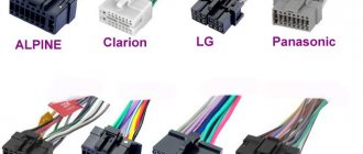
VAZ LADA Daewoo GM12 pin to OBDII 16 pin
G is shorted to plus H.
How to check the adapter, its pinout and why the adapter does not work was discussed in the previous article.
was found - this is the adjacent contact of the plus and fuel pump H and G.
For the correct operation of our cable, it is necessary to remove contact G (it is the fuel pump).
At first I wanted to unsolder the wire from the contact inside the adapter, but after disassembling it, it turned out that all the contacts inside were well insulated and filled with plastic.
Trying to get to the desired contact, there is a high probability of damaging nearby wires.
It would be possible to solder the contact together with the plastic, but instead we simply remove the unnecessary closed contact from the outside and get a working adapter.
Scary, but working.
Well, the most practical option would be to make such an adapter yourself. Fortunately, there are no problems with components now.
Well, or you can use a non-working adapter (with incorrect pinout). By redoing it, of course.
GM 12 PIN diagnostic connector VAZ connecting wires for diagnostics
Link to Wire and Connector
GM12 connector
Until 2002, injection VAZ 2108-99 were equipped with 12-pin rectangular connectors of the GM12 standard with the following pinout:
- A – “mass”;
- B – L-line diagnostics;
- D – CO potentiometer;
- G – fuel pump control;
- H – 12V power supply;
- M – K-line diagnostics.
Some wires may be missing, but this will not prevent you from conducting diagnostics. The easiest way to read the errors accumulated in the ECU memory is as follows:
- with the ignition off, connect terminals A and B with a jumper;
- turn on the ignition without starting the engine;
- the “Check engine” lamp will display code “12” three times, after which error codes will be issued, also three times each;
- completion of the operation also ends with the code “12”.
The first digit of the code is indicated by the number of “long” flashes of the lamp, the second - by “short” flashes.
Where is the diagnostic connector for the VAZ-2112?
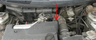
For a VAZ 2110 car, the connector for diagnosing and checking the engine is located under the instrument panel console on the right side. On some modifications the block is covered with a decorative cover.
- 12-pin connector: All injection models were equipped with a 12 PIN (GM12) connector, except for individual assemblies after 2002, which had an OBD-II connector installed.
- 16-pin connector: A 16 PIN connector was equipped with models after 2002, on which engine management systems were installed: BOSCH MP7.0 Euro-3, BOSCH M7.9.7, January-7.2.
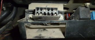
The location of the connector is indicated in the figure in position No. 3. The photo below shows the diagnostic block.
Information about the ECU and its location is written in the material “Diagnostics of VAZ 2112”. The following shows the pinout of the OBD2 and OBD1 connectors, as well as the assignment of the contacts of some ECUs that were installed on the Dvenashka.
The location of the OBD2 diagnostic connector and pinout for diagnostics can vary greatly from vehicle to vehicle. There is no single standard for location; the car's operating instructions or sleight of hand will help you here.
obd 2 connector
OBD 2 is an international diagnostic standard. It regulates the requirements for diagnostic equipment, unifies error codes - in general, almost everything related to diagnostics.
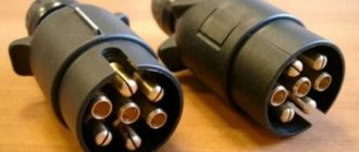
The VAZ 21099, produced since 2002, began to install a diagnostic connector that complies with the OBD 2 standard. Externally, it differs from the VAZ one in its trapezoidal shape:
You can carry out diagnostics on the injection VAZ 21099 using a car scanner (for example, based on the elm 327 processor). This is done with the preliminary installation of an application sold with a licensed scanner, even using a smartphone. By logging into the installed application, you can easily set error codes and also delete them.
True, the market is flooded with Chinese products that “do not see” the ECU of domestic cars, so you have two options:
- reflash the Chinese scanner;
- purchase a diagnostic cable connected to a laptop, Vag-com brand.
If you have an “old” GM12 block on your car, then the following adapter will help you connect to the scanner or cable:
However, in cases where you need to output errors to the computer, but there is no adapter, you can connect by independently connecting to any of the connectors for diagnostics, using the following correspondence diagram:
Pinout of connectors for connecting obd-2 usb-kkl cable to obd-1 (gm-12) VAZ connector.
Pinout of the old-style OBD 1 (GM-12) diagnostic connector for VAZ 2107, VAZ 2110, VAZ 2112, VAZ 2114, VAZ 2115 cars for connection to the USB-KKL cable if there is no adapter.
Connection (pinout) of the OBD-2 USB-KKL cable for connection to the old-style OBD-1 (GM-12) connector to VAZ 2107, VAZ 2110, VAZ 2112, VAZ 2114, VAZ 2115 cars without an adapter.
Also, if you wish, you can buy an adapter from OBD2 to OBD1 (GM12) VAZ 16pin here. Then the process of connecting a USB-KKL, ELM327 or other OBD2 adapter with OBD-1 (GM-12) will go much faster