Markings and types of connectors
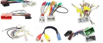
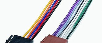
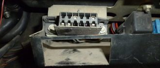
To answer your silent question about what kind of connectors there are in car radios, I must answer that most modern car radios are equipped with two standard connectors, designated by the abbreviation “ISO”. Each of these connectors is designed as an eight-pin rectangular plug, sometimes they are combined into one housing (see photo).
Car radio ISO connector pinout
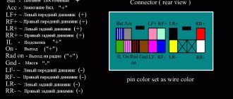
One of the connectors carries “power” circuits, that is, current consumption sources are connected to it, and is designated in the diagrams as a connector under the letter “A” and is colored brown. The second connector is intended for connecting the car’s acoustic system, in other words, speakers. Unlike the previous one, it is made in black and is designated on electrical circuit diagrams as connector “B”.
What connectors do car radios have?
Sometimes there are car radios with three connectors, but this is the exception rather than the rule. The same exception as non-standard connectors, which still have wiring with standard markings and in any case allow you to connect the wires of a standard speaker system with non-standard “connections” in at least two ways. So:
- “Skolkhoz”, namely, cut off the non-standard plug and overlap the wires, which “is not very good”, since over time the twist will become loose due to oxidation/shaking and, in the best case, you will have to do all the work again while simultaneously replacing the fuses.
Pinout of ISO connectors for car radios
- Buy an adapter (the price of which is in no way close to the amount of work that the method described above includes) and, without any problems, decorously/nobly, connect the car radio with other elements of the acoustic circuit of your car.
The choice of adapters at the moment is huge, and it is simply physically impossible for any troubles to arise in the use of this variety.
Car radio ISO connector pinout
Features of ISO connectors
Having a single ISO connector standard (electrical characteristics), many automakers, as well as audio equipment companies, can change its external shape at their discretion. That is, if you decide to replace an outdated Hyundai radio with a Mystery multimedia system, first of all, pay attention to the matching iso connection formats.
Also, when installing equipment, you can quite often encounter slight changes in the pinout colors of electrical cords from the standard pinout. Next, we will provide visual descriptions of the pinout of the ISO connector of a standard sample and for individual brands of sound-reproducing equipment (pinout of the ISO connector of the Prology 1715t radio, etc.). Judge for yourself how different they are from each other.
An alternative to ISO connectors are Fakra connections.
Pinout of a standard Euro connector
Let's look at the pinout of the Euro connector on a standard ISO plug - 10478
Upper power connector “A”
As already mentioned, this plug connects the sources and consumers of electrical current from the vehicle’s on-board network.
| №1 | Empty |
| №2 | Empty |
| №3 | Empty |
| №4 | Constant power |
| №5 | Antenna power |
| №6 | Backlight |
| №7 | Ignition |
| №8 | Weight |
Despite the fact that it has eight contacts, not all of them can be used in the car radio connection circuit. Let's figure out what the purpose is and what task each of these contacts performs:
- Connectors No. 1, No. 2, No. 3 and No. 6 are rarely used by default in the circuit of a budget car radio. Most often they are used to connect additional functions in more professional versions of the head unit, which significantly increase the comfort of a modern car, while the colors of the wires can be made in various color variations.
For example, among the additional functionality we can highlight the following:
- “ANT” output, which is used in cases where a retractable automatic antenna is installed in the car;
- “REMOTE”, which allows you to connect external amplifiers to the car radio, which means increasing the number of connected speakers (relevant for cars with a large interior, since in a small interior a large number of speakers creates a large load on the hearing organs, which is fraught with negative consequences);
- the “ILLUMINATION” option, which automatically, depending on the speed of the vehicle, controls the light signaling of the car radio - at higher speeds, the brightness of the display decreases and does not distract the driver from the process of driving the vehicle; when the vehicle stops, it returns to its initial parameters, which significantly the extent to which it affects road safety;
- as well as the currently very common “MUTE” option, which is turned on when using a mobile device connected to the car’s speaker system - when a receive/call signal passes through, the car radio automatically activates this output, which leads to a decrease in the volume of the music being played or to a complete shutdown car radio sound;
- Contact number four (indicated on electrical diagrams as “A4”) is responsible for turning on the entire acoustic system of the car. Through a separate fuse, this yellow wire is connected to the ignition switch terminal and is already powered from the battery.
Organizing the connection of the car radio according to this scheme is guaranteed to protect the battery from unauthorized discharge, since turning on the car radio is possible only when the key is turned in the ignition switch.
Reference. The need for this kind of connection arose due to the fact that the cascades of the car audio system continue to consume electrical energy even when turned off, which very often led to battery discharge.
Domestic car enthusiasts have improved the wiring diagrams for car radios as best they can, resorting to both manual toggle switches and installing an automatic relay to turn off the radio when setting the car alarm. But, as we see, it is this connection scheme that has received universal recognition. So:
- The fifth wire (A5), blue, is responsible for connecting the car antenna. It is designed for a maximum output current of 300 microamps, and if this value is exceeded, a large current can damage not only the output amplifier stages, but also the car radio itself as a whole;
- The contact with the positional designation “A7” in red is responsible for delivering voltage to the volatile memory of the car radio. This means that if you accidentally turn it off, all device parameters will be reset/reset to factory settings. The voltage on this wire is 12 volts;
- Well, the last wire of this connector, running in black insulation (A8), as you probably already guessed, is responsible for connecting the device to the ground of the car.
Advice! In order to protect the acoustic circuit, each of the supply wires must be equipped with a fuse-link. If periodic interruptions still occur during the operation of the head unit, then it is recommended to install a capacitor between contacts “A7” and “A8”, the capacity of which is selected experimentally. Essentially, it (the capacitor) will serve as a filter that will smooth out fluctuations in the electrical power circuit of the car's speaker system.
Bottom acoustic connector “B”
As already mentioned, all other peripherals of the car audio system, that is, speakers, are connected through connector “B”. The pinout of the car radio Euro connector under the letter “B” looks like this (see previous photo):
| №1 | Rear right "+" | Purple, "B1" |
| №2 | Rear right "-" | Purple black, “B2” |
| №3 | Front right "+" | Gray, "B3" |
| №4 | Front left "-" | Grey-black, "B4" |
| №5 | Front left "+" | White, "B5" |
| №6 | Front left "-" | White-black, "B6" |
| №7 | Rear left "+" | Green, "B7" |
| №8 | Rear left "-" | Green-black, "B8" |
The main part of car radios is initially designed to connect four channels, for which eight wires are used (two for each speaker).
Attention! The correct channel polarization plays an important role in the sound quality of your speaker system. Of course, if you mix up the wires and connect the speaker incorrectly, nothing bad will happen to it, but the entire speaker system will begin to work in abnormal mode - an incorrectly connected speaker will work in antiphase and the entire sound “collage” will be ruined.
DIY car radio ISO connector pinout
Advice! Elements of the car's acoustic system must be connected with wires having a minimum cross-section of 1.5-2 millimeters. In this case, wires with the largest cross-section must be used on power lines; wires with a smaller cross-section are not allowed, as this can not only spoil the sound, but can also lead to a complete failure of the entire system as a whole.
This information allows you to understand the very basis of the pinout of Euro connectors in modern car radios, which allows you to install almost any acoustic device in almost any car, without having any special knowledge. But you should also not forget about caution, especially when you are dealing with non-standard connectors and equipment/vehicles that have long been out of production, and even more so when they are used. For “complex” connections, I strongly recommend that you use testers and a multimeter for “testing” electrical circuits and subsequent “switching”.
Installers website
PIONEER GM-42
PIONEER radio connector PIONEER KE- 92 ZBM (BMW C Business RDS) PIONEER radio connector PIONEER CDX-M97512T NAKAMICHI CX-CS5110A PIONEER radio connector ]PIONEER KEH-1010QR[ PIONEER radio connector PIONEER KEH-1050QR PIONEER radio connector PIONEER KEH-1450 Radio connector PIONEER PIONEER KE-1900 PIONEER KE-2910 Radio connector PIONEER PIONEER KE-1700SDK Radio connector PIONEER PIONEER KEH-1850 PIONEER KEH-1950 Radio connector PIONEER PIONEER KEH-2500R Radio connector PIONEER PIONEER KEH-2600 PIONEER KEH-3600 Radio connector PIONEER ]PIONEER KEH-3800 (RDS) PIONEER radio connector PIONEER KEH-P4510 PIONEER radio connector PIONEER DEH-P443R PIONEER radio connector PIONEER DEH-624R PIONEER radio connector
PIONEER DEH-790SDK Radio connector PIONEER PIONEER DEH-2030R PIONEER DEH-1110MP Radio connector PIONEER PIONEER KEH-P8200 Radio connector PIONEER PIONEER KEH-8080 SDK Radio connector PIONEER PIONEER KEH-P5950 Radio connector PIONEER PIONE ER KEH-P6600R Radio connector PIONEER PIONEER DEH- M980RDS KEH-M8300RDS KEH-M9300RDS Connector for radio PIONEER PIONEER KEH-M7005W Connector for radio PIONEER PIONEER KEH-P6950 Connector for radio PIONEER PIONEER KEH-P7850 Connector for radio PIONEER PIONEER KEH-M7400RDS Connector for radio PIONEER ]PIONEER KEX-8250 Connector for radio PIONEER PIONEER KEH 8020 Connector radio PIONEER PIONEER KA-858 radio connector PIONEER PIONEER DEQ-9200 radio connector PIONEER PIONEER KEH-M9800 radio connector PIONEER PIONEER radio connector PIONEER PIONEER TS-LX80ii radio connector PIONEER PIONEER DEH-M6017ZH (Honda 391 00-S1A-E100) Radio connector PIONEER PIONEER KEH-5110 PIONEER radio connector PIONEER KEH-P8950 PIONEER radio connector
PIONEER KEH-P8810 PIONEER radio connector PIONEER KE-3500 SDK PIONEER radio connector PIONEER KE-2800 QR PIONEER radio connector
PIONEER KEH-P9250W Connector for radio PIONEER SAAB FX-M2016zsa Pioneer (Belgium) Connector for radio PIONEER PIONEER 3TF0 (FX-MG6006ZH BOSE changer ACURA) Connector for radio PIONEER Connector for radio PIONEER PIONEER KEX-M9076ZT (LEXUS) Connector for radio PI ONEER PIONEER-KEX-M9036ZT WHITE : (TO AMPLIFIER) PIONEER radio connector
BLUE: (POWER) PIONEER radio connector
GRAY:( TO CD CHANJER) PIONEER radio connector PIONEER FH-P404 PIONEER radio connector PIONEER CDX-P1210 (CD changer) PIONEER radio connector PIONEER DEH-P2500R PIONEER radio connector PIONEER DVH-P9988USB PIONEER radio connector PIONEER FH-P9 0 PIONEER radio connector PIONEER KEH-9508 Connector for radio PIONEER PIONEER KEH-M9600 Connector for radio PIONEER PIONEER KEH-P4022 Connector for radio PIONEER PIONEER KEH-P6020RB Connector for radio PIONEER PIONEER KEH-P660 Connector for radio PIONEER PIONEER CDX-7910 Connector for magnetic PIONEER radio connector PIONEER
PIONEER KEH-7150 PIONEER radio connector PIONEER DVH-P590MP PIONEER FH-P5000MP PIONEER DEH-P88RS PIONEER DEH-P75BT PIONEER radio connector PIONEER radio connector
PIONEER CELCIOR PIONEER radio connector
PIONEER KEH-P7025 Radio connector PIONEER PIONEER KEH-P2030R Radio connector PIONEER
PIONEER DEH-M6017ZH Radio connector PIONEER PIONEER DEH-P850MP Radio connector PIONEER
PIONEER DEH-3210UB PIONEER radio connector
PIONEER radio connector
PIONEER radio connector
PIONEER DEH-P80MP PIONEER radio connector
PIONEER radio connector
PIONEER radio connector PIONEER model: 5L7T-18C985-AB Installed on LINCOLN AVX-MG2247ZF PIONEER radio connector PIONEER radio connector PIONEER radio connector
PIONEER radio connector
PIONEER AVX-P7300 PIONEER radio connector
PIONEER DEN-P2530 PIONEER radio connector
PIONEER AVH-P5750 PIONEER radio connector
PIONEER DEN-P90 PIONEER radio connector
PIONEER DVH-P5000 PIONEER radio connector Pioneer PIONEER radio connector PIONEER radio connector
Pioneer Radio connector PIONEER Radio connector PIONEER Pioneer DEH-P7950UB Radio connector PIONEER
PIONEER radio connector
PIONEER DEH-6860 PIONEER radio connector PIONEER radio connector
Pioneer KEH-P7020R PIONEER radio connector
PIONEER radio connector Pioneer PIONEER radio connector PIONEER radio connector
PIONEER P-3850 PIONEER radio connector PIONEER radio connector
Pioneer PIONEER radio connector
PIONEER radio connector Pioneer PIONEER radio connector PIONEER radio connector Pioneer PIONEER radio connector PIONEER radio connector
Pioneer FC-7779 PIONEER radio connector PIONEER radio connector PIONEER HC-393 PIONEER radio connector PIONEER radio connector
PIONEER DVD+TV PIONEER radio connector PIONEER radio connector
PIONEER DEH-P3650 PIONEER radio connector PIONEER radio connector
Pioneer DEH-2460R Radio connector PIONEER Pioneer DVH-580MP Radio connector PIONEER
PIONEER FD-9999 PIONEER radio connector PIONEER radio connector PIONEER DEH-P1Y PIONEER DEH-P80MP PIONEER radio connector
Pioneer DEN-2950MP Radio connector PIONEER
Pioneer AVH-P6050 DVD PIONEER radio connector PIONEER radio connector
Pioneer AVH-P3100DVD PIONEER radio connector
PIONEER radio connector File with full connection You cannot download files from our server Pioneer AVH-P3200BT PIONEER radio connector
PIONEER radio connector PIONEER radio connector
Pioneer (No markings, arrived in an LC-470 from the Emirates) Apparently they used the Chinese one. PIONEER radio connector
PIONEER radio connector PIONEER radio connector
You may also like…
Cars
Removing and replacing the Renault Logan heater fan without dismantling the instrument panel
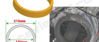
Cars
Requirements for the dimensions of a road train
Cars
Alternator. Device and principle of operation
Add a comment Cancel reply
How to properly connect to an electronic device
The concept of an interface as we know it today dates back to the 1960s. More precisely, in 1964, when the company developed its legendary IBM System/360 mainframe. It was then that the main tasks of any interface - physical or virtual - were formulated. They were to provide a standard connection for all devices.
Euro connectors
Initially, only a few types of standard inputs could be made to ensure compatibility between products from different manufacturers. This was a PS/2 port for the keyboard, an LPT port for the printer, and a connector for the PCI card. Nowadays, each type of connection has its own standard interface; this approach greatly simplifies the development and sale of any type of device and allows you to understand their built-in capabilities. Here are descriptions of the main communication elements, first of all, the designation of the button on the radio, which are used on the panels of Pioneer and other car radios.
Description of the buttons on the front panel of the radio for control (decoding)
| Button labels | Button function |
| A.F. | Different RDS frequency, automatic search when reception is poor |
| ALL OFF | Everything is off |
| AMS | Music sensor, works on the principle of playing a number of tracks equal to the number of clicks |
| ANG | Panel adjustment |
| ATA | The radio turns on automatically when you turn off and rewind media tracks |
| A.T.T. | Quickly reduces volume |
| BAND | Selecting a radio receiver |
| BEER | Enabling sound when pressing buttons |
| Blank Skip | Skips pauses longer than 8 seconds |
| BMS | Compensates for low frequencies when dropped due to the main device |
| BTM | Remembers the quality frequency of strong stations |
| CLK ADJ | Adjusts time |
| COLOR | Color |
| DISP | Display activation |
| DNPP | Selecting a CD in the changer |
| DNPS | Entering disc names |
| DSP | Activating the sound processor |
| EJECT | Remove the cassette from the cassette receiver or disc |
| EON | Reception of traffic information |
| FUNCTION | Switches the most used functions |
| INTO SCAN | Plays the recording for 10 seconds to search |
| LOS | Looks for stations, skipping with weak reception |
| LOUD | Tone compensation |
| M.RDM | Disc random playback |
| P.I. | Automatic search |
| PI SOUND | Switching to another frequency |
| PI MUTE | Muffled sound |
| POWER | Shutdown |
| PS | Listening to saved settings |
| PTY | Selecting a genre |
| RDS | Search for a station by metadata |
| RDM | Play disc tracks in any order |
| REG | Switching to the frequency of a radio station with RDS |
| Repeat Play | Replaying a track |
| SCAN | Scanning tracks and playing the beginning |
| SEL | Settings |
| SHUFFLE PLAY | Play available music in random order |
| SYSTEM Q | Tracking sound enhancement factors and showing them on the display |
| TA SEEK | Searching for a station with RDS |
| TC | Calling the tuner when rewinding |
Recent comments
- domznaniy on Comparison of LED lamps and energy-saving lamps. Which is more profitable?
- Vovan to the entry Comparison of LED lamps and energy-saving ones. Which is more profitable?
- mmoguider to the entry All-in-one or laptop. Which computer to choose
- Dmitry on Modern electric vehicles and their advantages
- Denis on How to get nice license plates on your car officially
see also
Comments 25
I have a similar problem. I called that there is constant power on pin 7, and after the ignition on pin 4. After turning off the ignition, there is no reset? The radio works as expected. What's wrong?
ps stock radio for Ford Galaxy 1999.
This means that the standard radio has a suitable pinout. A similar situation happened with Pioneer radios, when it was necessary to swap the red and yellow wires. Manufacturers of radio tape recorders provide this opportunity, implementing this in additional features. contacts on the cable
It is interesting that the ISO 10487 Standard itself defines the physical parameters of connectors for connecting an audio radio to a car. But it does not determine the purpose of the contacts! So says Wikipedia.
Heh. AND? Did someone connect it incorrectly?