Diagram of the engine control system (ECM) VAZ-2113, 2114 and 2115
Engine control system (ECM) diagram Euro-2 Bosch 7.9.7, January 7.2 VAZ-2113, 2114 and 2115 (2111-1411020-80, 81.82). Engine 1.5 liter 8 valve.
- — controller;
- — block of the ignition system harness to the ABS cabin group harness;
- — diagnostic block;
- — immobilizer warning sensor (APS);
- — immobilizer control unit (APS);
- - ignition coil;
- - spark plug;
- — nozzles;
- — electric fuel pump;
- — block of the ignition system harness to the electric fuel pump harness;
- — block of the fuel level sensor harness to the ignition system harness;
- — block of the ignition system harness to the injector harness;
- — block of the injector harness to the ignition system harness;
- - speed sensor;
- — idle speed regulator;
- — throttle position sensor;
- — coolant temperature sensor;
- — mass air flow sensor;
- — camshaft position sensor (phases);
- — oxygen sensor;
- — crankshaft position sensor;
- - knock sensor;
- — solenoid valve for purge of the adsorber;
- — block of the ignition system harness to the instrument panel harness;
- — controller power supply fuse;
- - ignition relay;
- — ignition relay fuse;
- — fuse for the power supply circuit of the electric fuel pump;
- — electric fuel pump relay;
- — electric fan relay;
- — block of the ignition system harness to the air conditioning harness;
- — pads of the ignition system harness to the front harness;
- — electric cooling system fan;
- — block of the instrument panel harness to the ignition system harness;
- — ignition switch;
- — instrument cluster;
- — on-board control system unit;
- - starter relay;
- — mounting block;
- A - to the “plus” terminal of the battery; B1, B2 - grounding points of the ignition system harness; 2115-3724026-11 — Ignition system harness;
Diagram of the engine control system (ECM) Euro-2 Bosch 7.9.7, January 7.2 VAZ-2113, 2114 and 2115 (21124-1411020-30, 21124-1411020-31.32). 1.6 liter 16 valve engine with individual ignition coils.
- — block of the ignition coil wiring harness to the ignition system harness;
- — block of the ignition system harness to the ignition coil wiring harness;
- — ignition coils;
- — immobilizer warning sensor;
- — immobilizer control unit;
- - spark plug;
- — nozzles;
- — diagnostic block;
- — block of the ignition system harness to the ABS cabin group harness;
- — controller;
- — electric fuel pump;
- — block of the ignition system harness to the fuel level sensor harness;
- — block of the fuel level sensor harness to the ignition system harness;
- — block of the ignition system harness to the injector harness;
- — block of the injector harness to the ignition system harness;
- — block of the ignition system harness to the side door harness;
- - speed sensor;
- — idle speed regulator;
- — throttle position sensor;
- — coolant temperature sensor;
- — mass air flow sensor;
- — oil pressure warning lamp sensor;
- — camshaft position sensor (phases);
- — oxygen sensor;
- — crankshaft position sensor;
- - knock sensor;
- — solenoid valve for purge of the adsorber;
- —
- — coolant temperature indicator sensor;
- — block of the ignition system harness to the instrument panel harness;
- — block of the instrument panel harness to the ignition system harness;
- - ignition relay;
- — ignition relay fuse;
- — fuse for the power supply circuit of the electric fuel pump;
- — electric fuel pump relay;
- — electric fan relay;
- — controller power supply fuse;
- — ignition system harness block to the air conditioner connector;
- — instrument cluster;
- — ignition switch;
- — electric cooling system fan;
- — on-board control system unit;
- — additional starter relay;
- — contacts of the 8-terminal blocks of the instrument panel harness and the front harness;
- — contacts of the 21-terminal blocks of the instrument panel harness and the rear harness;
- - trip computer;
- — diagnostic connector;
- A, E - to the “plus” terminal of the battery; B1 — grounding point of the ignition coil wiring harness; B2 — grounding point of the fuel level sensor harness; B3, B4 - grounding points of the ignition system harness; C - to the starter; D — to the driver's door interior lamp switch;
Diagram of the engine control system (ECM) Euro-3 Bosch 7.9.7+, M73 VAZ-2113, 2114 and 2115 (2111-1411020-30). Engine 1.6 liter 8 valve.
1 - controller; 2 — block of the ignition system harness to the ABS cabin group harness; 3 — diagnostic block; 4 — immobilizer warning sensor (APS); 5 — immobilizer control unit (APS); 6 — ignition coil; 7 — spark plugs; 8 — nozzles; 9 — electric fuel pump; 10 — block of the ignition system harness to the fuel level sensor harness; 11 — block of the fuel level sensor harness to the ignition system harness; 12 — block of the ignition system harness to the injector harness; 13 — injector harness block to the ignition system harness; 14 — speed sensor; 15 — idle speed regulator; 16 — throttle position sensor; 17 — coolant temperature sensor; 18 — mass air flow sensor; 19 — camshaft position sensor (phases); 20 — control oxygen sensor; 21 — crankshaft position sensor; 22 — knock sensor; 23 — solenoid valve for purge of the adsorber; 24 — rough road sensor; 25 — diagnostic oxygen sensor; 26 — block of the ignition system harness to the instrument panel harness; 27 — controller power supply fuse; 28 — ignition relay; 29 — ignition relay fuse; 30 — fuse for the electric fuel pump power supply circuit; 31 — electric fuel pump relay; 32 — electric fan relay; 33 — block of the ignition system harness to the air conditioner harness; 34 — pads of the ignition system harness to the front harness; 35 — electric fan of the cooling system; 36 — block of the instrument panel harness to the ignition system harness; 37 — ignition switch; 38 — instrument cluster; 39 — on-board control system unit; 40 — starter relay; 41 — mounting block;
A - to the “plus” terminal of the battery; B1 — grounding point of the fuel level sensor harness; B2, B3 - grounding points of the ignition system harness;
Diagram of the engine control system (ECM) Euro-3 Bosch 7.9.7+, M73 VAZ-2113, 2114 and 2115 (21124-1411020-10). 1.6 liter 16 valve engine with individual ignition coils and two oxygen sensors.
1 — block of the ignition coil wiring harness to the ignition system harness; 2 — block of the ignition system harness to the ignition coil wiring harness; 3 — ignition coils; 4 — immobilizer warning sensor; 5 — immobilizer control unit; 6 — spark plugs; 7 — nozzles; 8 — diagnostic block; 9 — block of the ignition system harness to the ABS cabin group harness; 10 - controller; 11 — electric fuel pump; 12 — block of the ignition system harness to the fuel level sensor harness; 13 — block of the fuel level sensor harness to the ignition system harness; 14 — block of the ignition system harness to the injector harness; 15 — injector harness block to the ignition system harness; 16 — block of the ignition system harness to the side door harness; 17 — speed sensor; 18 — idle speed regulator; 19 — throttle position sensor; 20 — coolant temperature sensor; 21 — mass air flow sensor; 22 — oil pressure warning lamp sensor; 23 — camshaft position sensor (phases); 24 — control oxygen sensor; 25 — crankshaft position sensor; 26 — knock sensor; 27 — solenoid valve for purge of the adsorber; 28 — diagnostic oxygen sensor; 29 — coolant temperature indicator sensor; 30 — block of the ignition system harness to the instrument panel harness; 31 — block of the instrument panel harness to the ignition system harness; 32 — ignition relay; 33 - ignition relay fuse; 34 — fuse for the electric fuel pump power supply circuit; 35 — electric fuel pump relay; 36 — electric fan relay; 37 — controller power supply fuse; 38 — ignition system harness block to the air conditioner connector; 39 — rough road sensor; 40 — instrument cluster; 41 — ignition switch; 42 — electric fan of the cooling system; 43 — on-board control system unit; 44 - additional starter relay; 45 — contacts of the 8-terminal blocks of the instrument panel harness and the front harness; 46 — contacts of the 21-terminal blocks of the instrument panel harness and the rear harness; 47 — trip computer; 48 — diagnostic connector;
A, E - to the “plus” terminal of the battery; B1 — grounding point of the ignition coil wiring harness; B2, B3 - grounding points of the ignition system harness; B4 — grounding point of the fuel level sensor harness; C - to the starter; D — to the driver's door interior lamp switch;
Location of the Lada Granta ECU
We can talk for a long time about how important the correct operation of the electronic control unit (ECU) is. The functioning of the heart of your car depends on it: from increased fuel consumption to the fact that the car may stall as a result of incorrect operation of the controller.
I would like to immediately convey a special greeting to the designer of AvtoVAZ, who came up with this arrangement of this block. In my opinion, I can't think of a worse place. See for yourself.
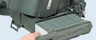
The ECU is located under the glove compartment under the passenger's feet and hidden under the upholstery. The upholstery is attached to the body on the right with a self-tapping screw.
- If your interior heater (radiator) leaks, the antifreeze will go straight to the control unit, causing almost 100% failure. Even though the Lada Granta is initially equipped with a good quality imported Visteon radiator.
- As you correctly noted, water can get in from under the hood. The rubber plugs on the Lada Granta are not of very good quality, so when they dry out, water will flow onto the controller. To prevent this from happening, check the condition of the rubber plug.
- If the drainage hole (which is shown in the video below) becomes clogged, water may flow into the cabin.
In general, as you understand, the location of the ECU on the Grant is not the best! So we just need to face it.
Schematic diagram (pinout) of connecting the front wiring harness on the Priora
The front part of the vehicle's electrical circuit is designed to supply voltage to the primary and auxiliary power circuits of the vehicle's on-board systems. The decoding of contact group chips is as follows:
- 1 – starter power supply;
- 2 – battery;
- 3 – charge supply from the generator;
- 4 – connecting block for the bundle (1 – 3);
- 5-7 – power supply to the device;
- 8 – engine compartment lighting lamp;
- 9-10 – head light;
- 11 – brake expansion tank level indicator;
- 12 – outside temperature;
- 13 – washer drive;
- 14 – external indication of reverse gear;
- 15 – cooling system fan;
- 16 – stove reducer;
- 17 – reserve resistor;
- 18 – wiper drive;
- 19 – interior relay and fuse module;
- 20 – stove motor;
- 21 – sound alarm indicator;
- 22 – horn power supply;
- A1/2, B1/2 – mass.
VAZ 2170 ECM harness connection diagram
This part is organized to supply power to the main instruments and engine control system of the Lada Priora. From here, voltage is supplied to the main components, units of the vehicle’s power plant, as well as control sensors and ECUs. The standard electrical circuit connection system (pinout) looks like this:
- 1 – ECU power supply;
- 2 – main block of the electronic system to the dashboard;
- 3 – distribution board;
- 4 – speedometer;
- 5 – road surface roughness sensor;
- 6 – indication of pressure in the engine crankcase;
- 7 – TPS;
- 8 – DTOZH;
- 9 – indication of antifreeze temperature sensor;
- 10 – mass air flow sensor;
- 11 – control XX;
- 12 – main relay of the fuel pump;
- 13 – VT circuit fuse;
- 14 – relay BZ;
- 15 – fuse of the above circuit;
- 16 – ECU fusible link;
- 17 – DPKV;
- 18 – power supply for mass air flow sensor;
- 19 – phase distribution;
- 20 – mixture detonation sensor;
- 21 – EMC for purging the adsorber;
- 22 – diagnostics of the air flow sensor;
- 23 – power supply to the ignition coil;
- 24 – supply voltage to spark plugs;
- 25 – power supply to fuel injectors;
- 26 – terminal from the ignition coils to the ECM;
- 27 – feedback from 26;
- 28 – ECM connector to the injection system;
- 29 – response to the previous output;
- A – phase on the battery;
- B1/2 – ignition mass;
- C1 – mass from short circuit.
Why ELM 327 does not connect to the VAZ 2110 ECU
So, why doesn't ELM327 see the ECU? What should I do so that the device can connect and see the block? Today you can find many different adapters for testing a vehicle on sale. If you buy an ELM327 Bluetooth, most likely you are trying to connect a low-quality device. Or rather, you could have purchased an adapter with an outdated version of the software.
ELM327 Bluetooth devices with outdated firmware use a different Bluetooth module that allows you to interact with two of the available six protocols. Accordingly, you can synchronize the device with a smartphone, but when you try to connect the device to the control unit, it will inform you that there is no connection with the ECU.
So, for what reasons does the device refuse to connect to the block:
- The adapter itself is of poor quality.
- Problems can be with both the device’s firmware and its hardware. If the main microcircuit is inoperative, it will be impossible to diagnose the engine operation, as well as connect to the computer.
- Bad connection cable. The cable may be broken or inoperative itself. The wrong version of the software is installed on the device, as a result of which it will not be possible to achieve synchronization (the author of the video about testing the device is Rus Radarov)
If you own a device with the correct firmware version 1.5, where all six of the six protocols are present, but the adapter does not connect to the ECU, there is a way out. You can connect to the unit using initialization strings, which allow the device to adapt to the commands of the machine’s motor control unit. In particular, we are talking about initialization lines for diagnostic utilities HobDrive and Torque for vehicles that use non-standard connection protocols.
Interpretation of the symbols for the rear wiring harness of the VAZ Priora
The rear part of the electrical wiring chain is responsible for the vehicle's lighting and peripheral systems. This includes lights, locks and windows. The pinout of tips and terminals looks like this:
- 1 – dashboard response;
- 2 – power supply for the door behind the driver;
- 3/28 – power supply for the front passenger panel equipment;
- 4 – maintenance of power windows and door locks;
- 5-6 turn signals;
- 7 – interior lighting;
- 8 – handbrake indication switch;
- 9-10 – aft dimensions;
- 11 – temperature inside the car;
- 12-15 – circuit breakers for lighting the interior of the machine;
- 16/17 – power supply to the devices of the aft right and front left doors, respectively;
- 18/19 – voltage to the rear right and left speakers, respectively;
- 20 – cigarette lighter power core;
- 21 – EBN;
- 22 – contact group of the cargo compartment lighting circuit breaker;
- 23 – heated rear windshield;
- 24 – luggage compartment lighting lamp;
- 25 – additional stop;
- 26 – power line to the electric lock of the luggage compartment lid;
- 27 – power supply for rear number plate illumination;
- A1-4 – mass;
- ХР1/3 – electrical package power controller.
Pinout for rear license plate illumination of VAZ 2170
The small harness, located in the luggage compartment, has only three terminals:
- 1 – power supply to the stern license plate lights;
- 2-3 – license plate lighting lamps;
- 4 – trunk lid lock motor.
Pinout for the driver's door of the Priora
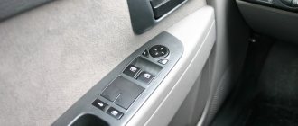
The harness is routed to supply power to the driver's door equipment. There is an output to the key panel installed in the armrest. There are six elements in total:
- 1 – additional terminal to the rear of the machine;
- 2 – line to the left fuse;
- 3 – electric window drive;
- 4 – armrest control module;
- 5 – door lock drive;
- 6 – rear view mirror control chip.
Front Passenger Door Wiring Harness
The unit duplicates the voltage supply from the center console to the passenger keypad located on the right side of the car. There are only seven connectors here:
- 1 – continuation of the main highway to the rear;
- 2 – terminal of the line to the right front speaker;
- 3 – window lift drive;
- 4 – electric window lift button;
- 5 – door lock drive;
- 6 – control of the position of the rear view mirror, as well as heated glass;
- 7 – continuation of the highway to the rear.
Rear door harnesses
The rear door wiring diagram has only two terminals. In this case, the side of the car is not of fundamental importance:
- 1 – continuation of the highway;
- 2 – locking drive.
Electrical diagram of the dashboard (Torpedo) VAZ-2170 Priora
Part of the on-board network is designed to power the main group of vehicle equipment. The control and display elements of the instrument panel are concentrated here. The wiring supplies power to loaded parts and critical components:
- 1-3 – contact group of the front harness;
- 4 – supply voltage to the aft connector;
- 5 – power supply from the fuse panel;
- 6 – contact group of stops;
- 7 – instrument panel indication;
- 8 – control of illuminators;
- 9 – contact group of emergency airbags;
- 10 – horn;
- 11 – power supply of the diagnostic unit;
- 12 – on-board PC control;
- 13 – ignition coil controller;
- 14 and 15 – supply voltage to the EUR control unit;
- 16 – control of power window equipment;
- 17 – alarm relay;
- 18 – wiper regulator;
- 19 – air flow distributor for the ventilation system;
- 20 – stove;
- 21 – heater drive;
- 22 – heated rear wind window;
- 23 – onboard clock;
- 24-25 – radio connection;
- 26 – emergency warning button;
- 27 – glove compartment lighting;
- 28 – control button for the glove box illumination;
- 29 – bundle of wiring for ignition;
- 30 – to the emergency airbag control board.
Pinout of the instrument panel VAZ 2170 Priora
The layout of the instrument panel is made in a simplified version to facilitate the replacement and installation of replacement parts. The decoding of the wiring connections at the factory terminals looks like this:
- 1 – EUR;
- 2 – emergency signal control;
- 3 – oil pressure sensor;
- 4 – indicator light for turning on the hand brake;
- 5 – immobilizer control unit;
- 6 – control unit for airbags;
- 7 – external lighting of the car;
- 8-9 – direction indicators;
- 10 – control of the combustible mixture injection system;
- 11 – disabling the front passenger SB;
- 12 – indication of seat belt buckles;
- 13 – operation of the brake system;
- 14 – reset button of the steering column switch;
- 15 – indication of the expansion tank of the brake system;
- 16 – ABS control unit;
- 17 – headlight high beam position switch;
- 18 – dashboard lighting;
- 19 – mass;
- 20 – receiving power from the battery terminal;
- 21 – ignition switch connector;
- 22 – fuel consumption sensor;
- 23-24 – BC mode switch;
- 25-26 – temperature sensor “overboard”;
- 27 – remaining fuel in the tank;
- 28 – speedometer;
- 29 – antifreeze temperature indication;
- 30 – tachometer;
- 31 – diagnostic terminal;
- 32 – power supply from generator (L).
Tuning and replacement of the center console on Lada Priora and Kalina
Modern versions of cars are supplied to the market with a restyled version of the tidy. Here, a relatively old generation, navigation and a liquid crystal display appeared. Installing an updated shield requires the following steps.
Selecting the required version
There are only two types of updated designs with and without a CAN bus. The nuance is that the versions are completely identical in appearance. In order to find out which variety is suitable, you need to check the production date of the car. Machines manufactured before 06, 2012 are not equipped with this technology. The article numbers for the new devices with navigation are as follows:
- 2170-3801010-50 without CAN;
- 2170-3801010-60 with CAN.
Also in the kit you need to purchase a navigation antenna and a steering column switch of the appropriate design.
Installation nuances
For Lada Kalina versions, all devices are not equipped with a CAN module. Also the old generation of Priora. Here the installation is carried out without modifications or nuances - just snap out the old panel, remove the terminals, and mount the new set on the stock fasteners. Next, you need to install a navigation antenna on the roof and connect it to the appropriate connector. The second case is when an old panel with a CAN unit, but without navigation, is replaced with an analogue one. Here it is necessary to rearrange the contact connectors of the standard wiring from positions 10-11 to sockets No. 28-29. In case of incorrect operation of the devices, the replaced wires are swapped with each other. After the repair is completed, the counters should reset to zero.
Appearance and body structure
As for the dimensions, the VAZ-2112 (16 valves) decreased in length by 93 mm. This change occurred in the rear overhang area. But despite all this, the size of the wheelbase did not transform. The body length was 4170 mm. And the height of 1676 mm and width of 1430 mm remained classic for the “tenth” family. The top line on this body very smoothly transforms into a rather small rear overhang and a huge wing. This design allowed the developers to make the car more manageable.
The one hundred percent zinc-coated body of the “10”, which at one time became very popular, is still susceptible to corrosion. Many owners of new cars did not consider it necessary to perform anti-corrosion treatment. The bottom was rapidly rusting to holes.
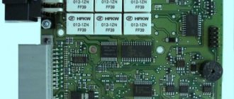
Pinout of the lighting control unit on Priora
The module is connected to the vehicle’s on-board network via chip No. 1118-3724500. The standard terminal pinout on a VAZ 2170 looks like this:
- G56b – for the gearbox for adjusting head lighting devices;
- 58b – output from lighting and instruments;
- 31 – neutral earth cable;
- Xz – 12 volts from pin 15 of the ignition switch;
- 56 – relay switch for high and low headlight modes;
- 1, 3 – connection of fog lights;
- 2, 4 – sending a signal to the controller;
- 58 – dimensions;
- 30 – power supply from the ignition switch design.
The standard electrical connection diagram (pinout) for the VAZ 2170 Priora has its shortcomings and strengths. However, thanks to the simple design, you can eliminate defects yourself, without the involvement of service station specialists.
Connector pinout January 7 2
I would like to immediately convey a special greeting to the designer of AvtoVAZ, who came up with this arrangement of this block. In my opinion, I can't think of a worse place. See for yourself.
The ECU is located under the glove compartment under the passenger's feet and hidden under the upholstery. The upholstery is attached to the body on the right with a self-tapping screw.
- If your interior heater (radiator) leaks, the antifreeze will go straight to the control unit, causing almost 100% failure. Even though the Lada Granta is initially equipped with a good quality imported Visteon radiator.
- As you correctly noted, water can get in from under the hood. The rubber plugs on the Lada Granta are not of very good quality, so when they dry out, water will flow onto the controller. To prevent this from happening, check the condition of the rubber plug.
- If the drainage hole (which is shown in the video below) becomes clogged, water may flow into the cabin.