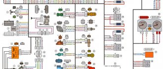
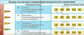
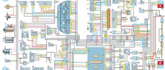
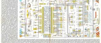
1 - injectors 2 - spark plugs 3 - ignition module 4 - diagnostic block 5 - controller 6 - block connected to the instrument panel wiring harness 7 - main relay 8 - fuse connected to the main relay 9 - electric fan relay 10 - fuse connected to electric fan relay 11 – electric fuel pump relay 12 – fuse connected to the electric fuel pump relay 13 – mass air flow sensor 14 – throttle position sensor 15 – coolant temperature sensor 16 – idle speed control 17 – oxygen sensor 18 – knock sensor 19 – crank position sensor shaft 20 – solenoid valve for canister purge 21 – immobilizer control unit 22 – immobilizer status indicator 23 – vehicle speed sensor 24 – electric fuel pump with fuel level sensor 25 – oil pressure warning lamp sensor 26 – coolant temperature indicator sensor 27 – oil level sensor 28 – phase sensor (installed on a car with a 16-valve engine) A - block connected to the anti-lock brake system (ABS) wiring harness B - block connected to the air conditioning wiring harness C - block connected to the electric fan wiring harness D - wires connected to the ignition switch (backlight lamp) E - block connected to blue-white wires disconnected from the ignition switch (when installing an immobilizer) F - to the “+” terminal of the battery G1, G2 - grounding points
The diagram uses the designation of the number of the circuit element to which this wire is connected, for example “-4-”. In some cases, in addition to the designation of the element number, it is given through an oblique fraction and the contact number, for example “-5/15-”. The diagram does not show the connection points of the pink-black, red and green with a red stripe wires. copy-paste from here thanks to him
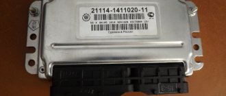
For online configuration you need a specific ECU January 5.1 - 2112-1411020-41 January 5.1 - 2111-1411020-61 Both computers have identical content with microcircuits, etc. They understand the operation of DBP (absolute pressure sensor), have phased injection (phase sensor), oxygen sensor (lambda probe). It is these three parameters that are most important for good firmware and good engine operation. These two ECUs differ only in the firmware of 16 and 8 valves, respectively. You can buy any of the two. I took the 41st.
ECU pinout January 5.1-41 (61) 1 Ignition cylinders 1-4. 2 Ground ignition wire. 3 Fuel pump relay 4 Stepper motor PXX(A) 5 Canister purge valve. 6 Cooling system fan relay 7 Air flow sensor input signal 8 Phase sensor input signal 9 Speed sensor 10 General. Oxygen sensor weight 11 Knock sensor 12 Sensor power supply. +5 13 L-line 14 Injector mass 15 Oxygen sensor heater 16 Injector 2 17 Recirculation valve 18 +12V power supply, non-switchable 19 Common wire. Electronics ground 20 Ignition 2-3 cylinders 21 Stepper motor PXX(C) 22 CheckEngine lamp 23 Injector 1 24 Ground of stepper motor output stages 25 Air conditioning relay 26 Stepper motor PXX(B) 27 Terminal 15 of the ignition switch 28 Oxygen sensor input signal 29 Stepper motor PXX(D) 30 Weight of sensors MAF, DTOZH, DPDZ, DD, DPKV 31 Reserve high-current output 32 . 33 Oxygen sensor heater. 34 Injector 4 35 Injector 3 36 Outlet. Intake pipe length control valve. 37 Nutrition. +12V after the main relay 38 Low-current backup output 39. 40 Reserve discrete input high 41 Request to turn on the air conditioner 42 Reserve discrete input low 43 Signal to tachometer 44 Air temperature sensor 45 Coolant temperature sensor 46 Main relay 47 Programming permission 48 Crankshaft position sensor. Low level 49 Crankshaft position sensor. High level 50 Recirculation valve position sensor 51 Request to turn on the power steering 52 Reserve discrete input low 53 Throttle position sensor 54 Fuel consumption signal 55 K-line
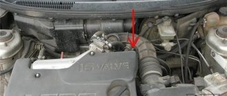
Where is the VAZ 2114 ECU located?
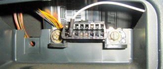
The block is located in the dashboard, directly under the tidy. To replace or dismantle, you need to unscrew the screws and remove the panel from the side, on the passenger side. Through the resulting hole you can see the ECU housing - it is installed inside a steel retainer.
To remove the electronic control unit, you need to unscrew the bolt and carefully pull out the housing, grasping the latch. Of course, it is necessary to turn off the power from the on-board network, otherwise expensive equipment can be damaged. A short circuit is the enemy of any electrical appliance, so be careful. It is advisable not only to remove ground from the battery, but also to disconnect the positive wire.
Reworking the ECU January 5.1.1 8 cl. in January 5.1 16 valves.
FROM 8-CL TO 16-CL
In order to convert the eight-valve computer January 5.1.1 2111-1411020-71 into a sixteen-valve one,
you need to solder the missing electronic components into it.
First of all, you need to remove the varnish applied to the block board. Take acetone and soak the entire board until the varnish becomes soft, then wash everything off with a brush.
For the conversion you will need the January 5.1.1 block itself and a set of electronic parts to convert the computer into a 16-valve one.
Let's look at a photo of January, designed for a sixteen-valve engine with phased injection and an oxygen sensor.
The photo shows all the elements that are not in 71 blocks.
At first glance, it seems like a lot of things are missing, but after studying the block board in detail, it turned out that half of these parts are not involved in the block at all.
Now comes the fun part.
It turns out that the block initially contains functions that are not used on the car, for example: 16-pin exhaust gas recirculation valve control, 36-pin intake pipe length valve control, 31-pin backup high-current output.
All this is not used in a production car, and one of the expensive microcircuits TLE5216G, MC33385DH, TY94085DH is used only to control the absorber valve (top photo) which also does not affect the operation of the engine, it can be disabled programmatically in the firmware by unchecking configuration.
The photo below shows an option for remaking the January 5.1.1 block with phased injection, a phase sensor, and an oxygen sensor, which is in no way inferior to the January 5.1 block 2112-1411020-41 With the appropriate firmware, the ECU block can be installed on both sixteen valve and eight valve engine.
However, you should not forget that January boards have different hardware implementations, new and old. See photo below.
Both of these blocks have different printed circuit boards for microcircuits. Look carefully at the paths that go to the microcircuits and you will see the difference, respectively, the microcircuits
MC33384DH and TLE5216G are not interchangeable.
If you decide to modify a block with one microcircuit, which serves as an injector control (phased injection), on all blocks with different boards, it is the bottom one as soldered in the photo.
On our website you can purchase a ready-made set of electronic components for independent modification of the January 5.1.1 block. After the modification, don’t forget to flash the block with the appropriate firmware.
IMPORTANT! Before ordering, disassemble your unit and make sure what board you have; when ordering, select a kit with the microcircuits needed for your unit.
Differences and replaceability of ECU January 5.1
Simultaneous injection.
These three blocks use simultaneous injection, are identical in wiring and are completely interchangeable with each other.
How does the ECU work?
At the heart is a microprocessor, which is responsible for the normal functioning of all key devices. On a VAZ 2114 car, the ECU collects data from sensors:
- Vehicle speed.
- Detonations.
- Lambda probe.
- DPKV.
- Air flow.
- TPDZ.
- Phases of injection of the air-fuel mixture.
- Coolant temperatures.
These are reading devices that collect information about the operation of an internal combustion engine. Why does he collect it? It is correct to divide and conquer by the following actuators:
- Fuel supply system (pump, injectors).
- Ignition system.
- Adsorber.
- Ventilation.
- Idle air control (yes, yes, this is not a sensor, but an actuator, no need to be confused).
- Automatic diagnostics.
The block diagram of the electronic control unit on the VAZ 2114 consists of three cascades, each of which has its own memory modules:
- A RAM unit (random access memory) is a system that has short-term memory. It stores all information about errors that occurred during operation during the current engine start. When the ignition is turned off (and the computer is de-energized), all memory is cleared and filled again the next time it starts.
- PROM is a programmable read-only memory device. This is the block in which the fuel map (firmware) of the electronic control unit is stored. It also permanently stores information about all system calibration results. And most importantly, this memory contains the algorithm of the internal combustion engine control system. This memory is permanent and is not erased even if the on-board network is completely disconnected. It is this block that is programmed when the “firmware” procedure is performed to improve the characteristics of the VAZ 2114 car.
- And the last block is the ERPZU. The memory unit is necessary to ensure the normal operation of the anti-theft system on the car. It stores passwords and encodings. Starting the engine is possible only if the data exchanged between the immobilizer and the EEPROM matches.
Description of "brains"
2114 is an on-board vehicle computer designed to control basic vehicle systems. The parameters of the control module affect both the functionality of certain regulators and the operation of the engine as a whole.
That is, the importance of this system cannot be denied
Controller Location
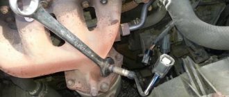
In VAZ 2114 and VAZ 2115 cars, the control module is installed under the center console of the car, in particular, in the middle, behind the panel with the radio. To get to the controller, you need to unscrew the latches on the side frame of the console. As for the connection, in Samar modifications with a one and a half liter engine, the mass of the ECU is taken from the power unit housing, from the fastening of the plugs located to the right of the cylinder head.
Location of the ECU in the Chetyrka
In cars equipped with 1.6- and 1.5-liter engines with a new type of ECU, the mass is taken from the welded stud. The pin itself is fixed on the metal body of the control panel near the floor tunnel, not far from the ashtray. During production, VAZ engineers, as a rule, do not securely fix this pin, so over time it can become loose, which will lead to the inoperability of some devices.
Design and principle of operation
The control unit of the electronic system operates in accordance with the indicators received from the sensors:
- speed;
- detonation;
- lambda probe;
- fuel injection phases;
- crankshaft position;
- throttle position;
- air flow meter;
- antifreeze temperature.
In accordance with the data received from these controllers, the control module controls the following systems:
- ignition;
- adsorber;
- injectors, as well as a fuel pump;
- ventilation and heating system;
- programs for diagnosing vehicle performance;
- idle speed regulator (video author - Evgeniy Vekhter).
As for the device, the control module structurally consists of the following components:
- RAM or random access memory. This module contains basic data about recently identified errors detected by the electronic system in the operation of various components. When the driver turns off the ignition, the RAM unit is updated, causing this data to disappear.
- PROM is the main element of the system; it contains the firmware of the control module. It should be noted that this memory block contains all the necessary data on the calibration of the “four” systems along with the general engine control algorithm. Unlike RAM, EPROM is a permanent memory, so the data stored in it is retained even after the ignition is turned off. If necessary, this module can be reconfigured, that is, reprogrammed, which can lead to improved power as well as vehicle dynamics.
- ERPZU - the primary function of this module is to protect the car. The EEPROM memory contains information from the anti-theft installation - passwords, as well as encoding of the main parameters. Starting the engine will only be possible if the EEPROM successfully checks with the data contained in the immobilizer memory.
Typical malfunctions: their symptoms and causes
What are the signs that indicate a faulty ECU:
- there are no control signals coming from actuators (IAC, flow meter, various sensors, etc.);
- there is no signal for interaction with the ignition system, fuel pump, injectors and other elements;
- when connecting a diagnostic tester, there will also be no connection with the electronic system;
- Burnt contacts and mechanical damage to the device may also be a sign.
What reasons contribute to the failure of the control device:
- electrical circuit shorted or broken;
- improper electrical repairs, during which errors were made, in particular, we are talking about installing or repairing an anti-theft system;
- lighting a dead battery from a car with the engine running;
- a breakdown of the unit can be caused by incorrect connection of the battery terminals - plus instead of minus and vice versa;
- disconnecting the battery contacts when the engine is running;
- moisture on the electronic system module board;
- mechanical damage to the device as a result of an accident (the author of the video about repairing the control module in a garage is the Auto Practice channel).
Repair and diagnostics of control units
The VAZ 2114 controller often breaks down. The system has a self-diagnosis function - the ECU queries all components and issues a conclusion about their suitability for operation. If any element fails, the “Check Engine” lamp will light up on the dashboard. It is possible to find out which sensor or actuator has failed only with the help of special diagnostic equipment. Even with the help of the famous OBD-Scan ELM-327, loved by many for its ease of use, you can read all engine operating parameters, find the error, eliminate it and delete it from the memory of the VAZ 2114 ECU.
Of course, it is wrong to simply delete errors. Be careful, because malfunctions don’t just appear. A good example is that a friend’s oxygen sensor broke down. And every other day he cuts down the mistake so that “it doesn’t become an eyesore.” But the reason lies in a faulty lambda. But what to do if the ECU does not want to respond to the scanner at all? Then check the following:
- Is there any mechanical damage to the housing, including oxidation and corrosion?
- The fuse is working properly, there is voltage and a connection to the power supply minus.
- Is the device overheating?
How to remove the mounting block - all steps in one video
Left: If the turn signals work properly but the hazard warning lights do not turn on, the cause is usually a faulty hazard warning light switch. If you press the switch firmly several times, most often it will start working normally. If this does not happen, then remove the switch (2), squeezing its locking tabs and removing it from the groove, check the contacts of the pin connection (1). Right: When installing the brake light switch (2), it must be pressed against the pedal support (3) so that the switch pin also presses the switch when the pedal (4) is released. For perfect operation, the pin block (1) must be correctly connected.
Types of ECU VAZ 2114
The car was produced for more than 10 years, constantly improved, the characteristics became better and better. Of course, this was achieved through the use of new motors, sensors, and actuators. And most importantly, thanks to the installation of control units, whose operating speed is much higher (you have all heard about the frequency of processors; it is on this parameter that the characteristics of internal combustion engines depend today).
January-4 and GM-09
Until 2003, these electronic units were installed. They had a very wide range of models, the main difference between them was the presence or absence of a resonant-type knock sensor. The price of a VAZ 2114 ECU of the “January-4” type is no more than 6,000 rubles. The list of modifications is given in the table:
| 21114-1411020-22 | January-4, without oxygen sensor, RSO, 1st production version |
| 21114-1411020-22 | January-4, without oxygen sensor, RSO, 2nd production version |
| 21114-1411020-22 | January-4, without oxygen sensor, RSO, 3rd serial version |
| 21114-1411020-22 | January-4, without oxygen sensor, RSO, 4th production version |
| 21114-1411020-20 | GM,GM_EFI-4,2111 with oxygen sensor, USA-83 |
| 21114-1411020-21 | GM,GM_EFI-4,2111 with oxygen sensor, EURO-2 |
| 21114-1411020-10 | GM,GM_EFI-4,2111 with oxygen sensor |
| 21114-1411020-20h | GM, RSO |
Electronic control units ITELMA 5.1, January 5.1.Х, Bosch M1.5.4
These ECUs belong to the next generation, they were successfully used on cars of models 2113 and 2115. If you are the owner of a VAZ 2114 car, which was released in 2013 or later, then the method of injection of the fuel-air mixture can distinguish it from its relatives: phased, pair-parallel or simultaneous. In general, all three ECUs (January, Bosch and Itelma) are complete analogues of each other. Modifications “January” and ITELMA:
| 21114-1411020-71 | January-5.1.1, without sensor acid, CO |
| 21114-1411020-71 | January-5.1.1, without sensor acid, CO |
| 21114-1411020-71 | January-5.1.1, without sensor acid, CO |
| 21114-1411020-71 | January-5.1.1, without sensor acid, CO |
| 21114-1411020-71 | January-5.1.1, without sensor acid, CO |
| 21114-1411020-72 | ITELMA, without sensor acid, CO |
| 21114-1411020-72 | ITELMA, without sensor acid, CO |
| 21114-1411020-72 | ITELMA, without sensor acid, CO |
| 21114-1411020-72 | ITELMA, without sensor acid, CO |
Modifications of BOSCH electronic control units:
| 21114-1411020 | Without sensor acid, RSO |
| 21114-1411020 | Without sensor, acid, CO (registered with CO scanner) |
| 21114-1411020-70 | BOSCH, without sensor acid, RSO |
| 21114-1411020-70 | BOSCH, without sensor acid, RSO |
On VAZ 2114 cars produced in 2003-2007, you can most often find “January-5.1.1”. The price of such a block ranges from 7000-8000 rubles. On export versions of cars, as a rule, a Bosch brain was installed, the price of which was the same.
Commercial firmware JANUARY 7.2 for HBO
| Single-mode versions | |
| 201CB5711183 – 1411020-22 | Single-mode version optimized for basic LPG movement. Without DC, with CO adjustment from diagnostic equipment. Cost 1000 ₽. |
| 203RB402111 – 1411020-81(82) | Single-mode version optimized for basic LPG movement. Without DC, with CO adjustment from diagnostic equipment. Calibration by Aviacop Tuning Lab. Cost 1000 ₽. |
| 204RB4021114 – 1411020-31(32) | Single-mode version optimized for basic LPG movement. Without DC, CO adjustment with diagnostic. equipment. Protocol Russia-83. Cost 1000 ₽. |
| 205RB4021124 – 1411020-31(32) | Single-mode version based on the I205DX53_RCO software, optimized for the main movement on the HBO. Without DC, with CO adjustment from diagnostic equipment. Protocol Russia-83. Calibration by Aviacop Tuning Lab. Cost 1000 ₽. |
| 226BX1221067 – 1411020-11(12) | Single-mode version optimized for basic LPG movement. Without DC, with CO adjustment from diagnostic equipment. Calibration by Aviacop Tuning Lab. Cost 1000 ₽. |
| Dual mode versions | |
| 201CDB5711183 – 1411020-22 | Dual-mode Standard/Butane version. When switching to GAS, the injectors and BN are switched off by software. Cost 1200 ₽. |
| 203DRB402111 – 1411020-81(82) Dual-mode version | Dual-mode version Speaker/Butane. The dynamic commercial version I203DX36 is used as the gasoline version, and I203RB40 as the butane version. When switching to GAS, the injectors are switched off programmatically. Cost 1200 ₽. |
| 204DRB4021114 – 1411020-31(32) Dual-mode version | Dual-mode version Speaker/Butane. The dynamic commercial version I204DX55 is used as the gasoline version, and I204RB40 as the butane version. When switching to GAS, the injectors are switched off programmatically. Cost 1200 ₽. |
| 205DRB4021124 – 1411020-31(32) Dual-mode version | Dual-mode version Speaker/Butane. The dynamic commercial version I205DX53 is used as the gasoline version, and I205RB40 as the butane version. When switching to GAS, the injectors are switched off programmatically. Cost 1200 ₽. |
| 226BP1221067 – 1411020-11(12) Dual-mode version | Dual-mode version Dynamic/Butane for “Classic”. The dynamic commercial version I226FX12_RCO is used as the gasoline version, and I226BX12_RCO as the butane version. BN and injectors cannot be turned off by software, an emulator is required. Cost 1200 ₽. |
| 226BFX5321067 – 1411020-11(12) Dual-mode version | Dual-mode version Dynamic/Butane for “Classic”. As a basic version, a dynamic commercial version based on “front-wheel drive” software was used; when switching to GAZ, the injectors are turned off by software, and a correction was made to work with LPG. Cost 1200 ₽. |
| 214BXF2 Dual mode version | Dual-mode version Dynamic/Butane to replace Bosch M7.9.7 controllers for January 7.2 Niva vehicles. As a basic version, a dynamic commercial version is used based on “front-wheel drive” software, with 2 cooling fans; when switching to GAS, the injectors are turned off by software, and a correction has been made to work with LPG. Version for fuel systems with return. Cost 1200 ₽. |
| 220BXF2 Dual mode version | Dual-mode version Dynamic/Butane to replace Bosch M7.9.7 controllers for January 7.2 Niva-Chevrolet vehicles. As a basic version, a dynamic commercial version is used based on “front-wheel drive” software, with 2 cooling fans; when switching to GAS, the injectors are switched off by software, and a correction has been made to work with LPG. For fuel systems without return. Cost 1200 ₽. |