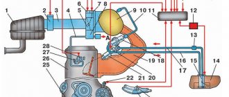
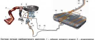
After the active introduction of an injection power system on various VAZ models, the overall design of the car became more complex. As you know, an injector, unlike a carburetor, cannot dose fuel itself. To solve the problem, control of the fuel injectors was transferred to the electronic engine control unit (ECU) or controller, better known as a computer or “brains”.
On the one hand, by installing the brains in the VAZ, the manufacturer made the engine more economical and less toxic. However, on the other hand, the control system has become more complex, and a large number of additional solutions and devices have appeared. Next, we will look at what features the VAZ electronic unit has, where it is located on different models, what functions the ECU performs, etc.
Description of "brains"
The VAZ 2110 is considered the first vehicle in the domestic automobile industry equipped with an injection engine. The power unit is controlled by an ECU, an electronic device that determines the basic parameters of engine operation in accordance with sensor signals. In fact, the ECU of a VAZ 2110, VAZ 2112 or any other model is the “brains” of the car, the operation of which affects the functionality of the vehicle as a whole.
Control controller in VAZ 2110
In the “Tens”, as well as the VAZ 2112, there are 16 valves and other models equipped with BOSCH 7.9.7 or January 7.2 systems, one M6 screw is installed in the head. From this screw the mass is taken to the ignition coils, and the mass is taken directly to the control model in the cabin. Typically, the mass is a welded stud mounted on the ECM bracket, particularly behind the center console, behind the left screen. In this case, the mass is transferred to the bracket through a pin, which is welded on the engine shield in the middle. It should also be noted that the nut on this stud is not usually tightened.
Control unit location
Now let's consider the location of the VAZ 2110 ECU. This device in the Ten is located under the center console, in its lower part, in particular, under the control panel. In order to gain access to the control module, you must remove the plastic panel on the passenger side, to do this you will have to use a Phillips screwdriver. Once you remove the cover, you will see many different wires, plugs, and safety devices. The controller itself is located behind them, it is screwed to the bar in a horizontal position.
The arrow indicates the location of the ECM module behind the center console
Signs of the need for internal combustion engine repair
The reasons why the operation of the engine is disrupted are arranged in a small list, starting with refusal to start and ending with floating idle speed (this problem was removed on the 127 “engine”). Not all breakdowns end in capital damage - sometimes it’s enough to add oil, sometimes it’s enough to adjust the ECU settings.
Compression reduction
A decrease in cylinder compression below 16 atmospheres is a bad sign. Such a high limit corresponds to a compression ratio of 11.
Knocks in the engine
Engine knocks can come from several points. These could be hydraulic compressors, timing belt rollers or pins. The knocking noise could also be caused by low oil level. The answer to the question will be given by a thorough detailed inspection of all parts of the unit and checking the oil level.
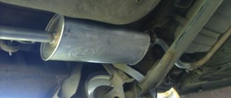
Blue smoke from the exhaust pipe
The blue smoke that comes from the exhaust pipe appears when oil enters the combustion chamber. It can leak either from the valves or from under the piston. The result is the same: the oil is eaten up and blue smoke pours out of the chimney. Once the leak is located, half the problem will already be solved.
Troit motor
Sometimes in the cold the engine may stall - don’t be alarmed by this, because it may simply be one of the spark plugs that fails. In this case, we advise you to simply restart the engine and it will stop running.
How much does it cost to overhaul a Priora engine - average price
Self-repair of a Priora engine with 16 valves costs an average of 16-20 thousand rubles. The cost depends on the severity of the breakdown and may be lower or higher than this average range. Repairing a Priora engine can be entrusted to the wrong hands, but then you will have to pay for the work - sometimes the cost of repairs reaches as much as 40 thousand rubles.
This is an unreasonably inflated figure, because, as practice shows, you can rebuild the engine on a Priora, working at a moderate pace, in just three days - and three days of work is definitely not worth that kind of money. Don’t be afraid of not being able to cope - your Lada is easy to repair, and using the advice and “tutorials”, you will conquer even such a task that is impossible at first glance.
Frequent malfunctions of the VAZ electronic control unit
Considering that the controller is a complex electronic device, failure of the ECU cannot be ruled out. As a rule, the causes of ECU malfunction can be different, ranging from mechanical damage to software failures.
For example, a common cause of breakdowns is overheating or liquid ingress. As practice shows, on the Lada Samara the ECU is located near the heater radiator. It is not difficult to guess that a radiator leak and coolant entering the controller often disables this device.
We also recommend reading the article about what the ELM327 diagnostic adapter is. From this article you will learn about the purpose, functionality, and features of selecting the ELM327 scanner.
Also, voltage surges in the on-board network lead to the fact that individual parts in the control unit burn out, and the memory bank with firmware suffers. For example, this happens if the battery terminals come loose. Also, poor contact with the spark plugs or high resistance of the explosive wires form an electromotive force in the primary winding of the ignition coil. The result is a breakdown of the output transistors of the control unit.
In this case, the check engine light does not always light up on the panel, but the engine malfunctions. In such a situation, when no other causes have been identified, what is needed is not diagnostics of the engine and systems, but professional diagnostics of the car's ECU, which can only be performed by an experienced specialist. Often, after checking, the unit may need to be replaced, since ECU repair is often not recommended.
Benefits of tuning
The main advantage of this tuning is the ability to improve the performance characteristics of the car without interfering with the engine itself. There is no need to change the head, install different pistons or spider. It is enough to install a different firmware on the VAZ, then the car will become more responsive to the accelerator pedal. The next plus is the speed of installation. Upgrading the VAZ-2114 firmware will take no more than twenty minutes of time. In this case, you can always return the ECU to its factory settings.
Another advantage of the control unit firmware is the removal of engine errors. They can occur when the catalyst is removed or the oxygen sensor is faulty. Since many VAZ-2114 owners install a flame arrester instead of a catalyst, the “Check” is constantly lit on the instrument panel. With the new firmware, “Check” will not bother the owner. And with computer diagnostics there will be no errors in the exhaust system.
There are many programs for flashing VAZ firmware. One will allow you to achieve maximum fuel efficiency. The other will improve dynamic performance. The third will allow the 16-valve engine to run on 92 gasoline without detonation and overconsumption.
About LADA 2114 engines 1st generation (2001 - 2013)
The VAZ 2114, popularly known as a four, is a popular front-wheel drive five-door hatchback, released to replace the VAZ 2109. The car was released in 2001. It is a representative of the Samara 2 series, along with the three-door VAZ 2113 and the VAZ 2115 sedan. In fact, the VAZ 2114 is a restyling of the old nine. The appearance has become more modern, and the interior has also been updated. The VAZ 2114 can be called a kind of “people’s” car, since its popularity among the population was enormous. In the article we will look at the engines that were installed on the VAZ 2114, we will touch on their characteristics and disadvantages.
ENGINE 2114 / 2111
The VAZ 2111 engine, which is popularly called 2114, is generally the eighty-third engine. However, unlike 21083, 2114 uses an injector rather than a carburetor. In addition, the 2114 is characterized by the presence of a floating connecting rod pin and a different camshaft. Finally, the 2114 has more power. Engine VAZ 2114 1.5 l. in-line, injection, with four cylinders, has an overhead camshaft, the timing drive uses a belt. In this case, if the belt breaks, the valve slider does not bend.
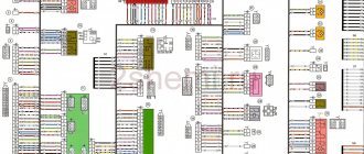
What kind of ECUs are installed on the VAZ 2110
Earlier I already talked about what kind of ECUs are installed on the VAZ 2114, if you are interested, read this article! So, dozens of electronic control units are installed with similar ones.
January 4 – technical specifications for which VAZ 2110 models are installed
One of the most common ECUs installed on the VAZ 2110 is January 4.
Structural management system January 4
January 4 was installed on the first generation VAZ 2110 model of 1999. Of course, this is not the most advanced ECU for a VAZ, but it still has a number of advantages, which I will talk about later.
Bosch M1.5.4 - advantages and disadvantages of use in the VAZ 2110
For Euro-2 toxicity standards, new modifications of block M1.5.4 appear (has an unofficial index “N”, to create an artificial difference) 2111-1411020-60 and 2112-1411020-40, satisfying these standards and incorporating an oxygen sensor, catalytic neutralizer and adsorber.
ECU Bosch M1.5.4
Also, for Russian standards, an ECM was developed for 8-class. engine (2111-1411020-70), which is a modification of the very first ECM 2111-1411020. All modifications, except the very first, use a wideband knock sensor. This unit began to be produced in a new design - a lightweight, leak-proof stamped body with an embossed inscription “MOTRONIC” (popularly “tin can”). Subsequently, ECU 2112-1411020-40 also began to be produced in this design. Replacing the structure, in my opinion, is completely unjustified - sealed blocks were more reliable. New modifications most likely have differences in the circuit diagram towards simplification, since the detonation channel in them works less correctly, the “tins” “ring” more when using the same software.
January-5 – description and technical characteristics of the VAZ 2110 ECU
In parallel with the M1.5.4 system, AvtoVAZ, together with ELKAR, designed a functional analogue of the M1.5.4 block, which was called January-5.” Initially, versions were released for Euro-2 standards (2112-1411020-41) containing an oxygen sensor, catalytic converter and adsorber. Later, mass production and installation of systems based on control units began:
- “January-5.1.2” for 16 (2112-1411020-71).
- “January-5.1.1” for 8 (2111-1411020-71) valve engines.
All these units have software and calibrations developed by AvtoVAZ OJSC. For classic cars, the January 5.1.3 2104-1411020-01 modification is used in the Euro-2 configuration, without a knock sensor.
ECU VAZ 2110 January 5.1
It differs from version 5.1 only in the unsoldered elements of the detonation channel. In December 2005, NPP Avtel released for spare parts (this was never supplied to the VAZ conveyor!!!) ECU “January 5.1.x” with modified hardware.
ECU VAZ 2110 BOSCH MP7.0H
The next generation of ECUs for VAZ cars was Bosch MP 7.0. In this modification, both the hardware and software were developed by Bosch, the final calibration and fine-tuning of the systems was carried out by AvtoVAZ OJSC. This family is also expanding and has already been supplemented with systems meeting Euro-3 standards for 8 and 16-valve engines of front-wheel drive vehicles, as well as for all-wheel drive vehicles VAZ-21214 and VAZ-2123 (Euro-2 and Euro-3 standards).
A FLASH chip with a capacity of 256 Kb is used as ROM in these blocks, of which only 32 Kb contain calibration tables and can be read and rewritten. More precisely, you can write all 256 KB, but only read 32 KB. Reading/writing of these blocks (without opening the blocks) is supported only by Combiloader from SMS-Software. It is also possible to program the flash with an external programmer via an adapter connected to the ECU bus.
ECU VAZ 2110 BOSCH MP7.0HThis ECU uses a 16-bit B58590 processor (internal marking from Bosch), a 20-bit bus and 29F200 flash memory is used as ROM for storing software and calibrations. ECUs of different modifications differ in hardware. The ECU for E3 (-50) standards has an additional driver for the heater of the 2nd oxygen sensor. There may also be differences in the DTV channel. A beautiful paper sticker (there are such things), on top of the standard nameplate - most likely the brainchild of OPP, such blocks were installed on some Niva and Nadezhda cars, converted to OPP from ordinary Niva ones. This type of ECU supports non-disabled driver diagnostics. Therefore, when installing gas equipment on them, it is strictly necessary to use continuous shutdown of the injectors.
DMRV of VAZ 2114 car
VAZ 2114 cars were equipped with several types of engines: 8 valves of 1.5 liters and 1.6 liters, as well as 16 valves of 1.6 liters. Until 2005, January 5 series ECUs were installed on the motors, then the manufacturer updated the controllers. Since 2006, these machines have been equipped with a January 7 series ECU, or imported analogues of BOSCH 7.9.7. Why do you need this information? Depending on the version of the ECU, mass air flow sensors on the VAZ 2114 were of different types. This causes some difficulties when replacing the sensor, but detailed information can be found in the car's passport.
- Air flow sensors of the 004 series were installed on early versions of cars.
- Then an updated mass air flow sensor was introduced for the VAZ 2114, series 037. The measuring channel on it was modified to reduce air flow pulsations. The new flow meter with modified characteristics is fully compatible with old ECUs with an oxygen sensor, so the replacement did not lead to changes in calibrations in the fuel-air mixture formation system.
- After switching to the January 7 series and BOSCH 7.9.7 controllers, we also had to change the air flow sensor on the VAZ 2114. The new version with index 116 is produced with an updated design. The calibration of the sensor has also been updated, so there is no backward compatibility.
The BOSCH 116 air sensor has many analogues, including the Russian Itelma and Avtel.
Information: There is an opinion among VAZ 2114 owners that the air flow sensor of the 116 series is better than the 037, and it can be replaced to increase engine output. In fact, this is not the case; the calibration of the mass air flow sensor is developed for a specific motor and is taken into account when programming the ECU.
As an example, the graph in the illustration:
Obviously, when the air flow rate is more than 100 kg per hour, the voltage that the VAZ 2114 series 116 air sensor produces changes by 0.2 volts. When the data is read by the engine controller, this makes a significant correction in the proportions of the fuel mixture.
Video “No spark and blown fuse - repairing the ECU”
What to do if there is no spark and the fuses are constantly blowing - the video below shows the process of repairing the control controller in a garage (the author of the video is the Auto Practice channel).
I came across an article by McSystem. Actually, here it is below
In January - about Januarys. Again and in detail about the ECM-ECU masses
One of the rather serious problems affecting the stable operation of engines controlled by the January ECU (7.2, 7.2+, M73, 7.9.7) is the “mass problem” of the ECM. Moreover, the point is not so much in bad (or uncrimped) contacts and their fastenings, but rather in the rather incorrect wiring of the ECM harness itself. And the solution is not in “pulling a fancy cable (KG-25 or 50)” to the ECU. Therefore, this material will be devoted to a technically competent approach to solving this problem. What is described below is a kind of compilation, or an attempt to “chew” what has been published more than once, in particular on ChipTuner.ru, and to convey to readers the specifics of solving this problem. The articles by I.N. turned out to be the most complete and informative. Skrydlova, (aka Aktuator) “About the masses”, “MASS: AN UNEXHAUSTABLE SOURCE OF GLITCHES” “ONCE AGAIN ABOUT THE MASSES” Oleg Bratkov. Many years ago, having read and comprehended what was written, I implemented it on my typewriter. I completely agree with the conclusion of the author (aka Aktuator): “All the assurances of AVTOVAZ OJSC about improving the quality of electrical connections in manufactured vehicles are not worth a penny. In most cases, it is possible to achieve normal operation of the engine under the control of the ECM I 7.9.7 and January 7.2 only by carrying out additional, and not accepted by the manufacturer as a warranty, work to change the electrical circuit of the car.”
So, on to the topic! Classic ECM 21124 with ECU January 7.2(+) or M7.9.7 Electrical connection diagram of ECM EURO-2 M7.9.7, January 7.2 LADA 2110 with engine 21124. 21124-1411020-30, 21124-1411020-31.32
Fig. 1 ECM 21124 January 7.2, M7.9.7 Noticed, often described and characteristic problems - unstable idle speed, freezing speed, “jerking” of the engine at start and operation of the cooling fan, unreasonable jumps in the electrical parameters of the ECM during diagnostics. And this is not the entire list. And the whole problem is a rather incorrect wiring of the harness masses, not in relation to the body, but to the ECU. Therefore, in this article you will not see recommendations for tightening the “hoses” of additional mass to the ECU, due to its complete uselessness. This is not a newfangled “razmasovka” or “razminusovka”... Don’t get your hopes up!
The main idea voiced by the authors is that the wiring of the power lines of the ECU and fan and low-current sensor masses is fundamentally incorrect. Rice. 12
Fig.2 Ground connections of the ECM. S6, S7, S8
The sensors must be connected to the ground bus of the ECU board and not have contact with the body! There should be no flow of pulsed and direct currents of the ECU and IM in the sensor mass circuit. And the ECU is securely connected to the body. The rationale is to eliminate the influence of ECU currents (pulse and constant) and fan current on the reliability of sensor readings. Classic approach with data collection and processing systems! But not from AvtoVAZ designers, as usual... Now, in order
Fig. 3 Masses according to AvtoVAZ, or how not to do it
1. The ECU masses are combined into three crimps S6, S7, S8, which are combined with each other and TWO bends are already made from them to the body studs B3, B4. 2. A switched minus fan with a rated current of 12A is connected to S6, and at the peak at start - all 20A! ! ! Which in itself is terrible! 3. All this is connected (screwed) to the ECU bracket, which in turn is very flimsily connected to the body. The engine ECM consists of sensors and actuators (AM). Sensors can be easily divided into analog and discrete. Analogue – mass air flow sensor, air pressure sensor, diesel sensor, DD. The output signal of these sensors is a voltage in a certain small range, usually 0 - 5V. For this group, any (even small) interference has a serious impact on the result. Discrete ones - DC (to some approximation), DF, DS (Speed Sensor) - are less critical to interference, because the output signal has two fixed levels high and low, and intermediate levels are not interesting to the ECU. Actuators - ignition coils, injectors, canister valve, DC heating, IAC, relays and other sources of large pulsed and direct currents along the negative (mass) bus of the ECU. To understand what the developers were up to, let’s look at the diagram in Fig. 3 – this is a fragment of the main ECM diagram in expanded form. It immediately catches your eye - the masses of the most sensitive and responsible sensors, mass air flow sensors and diesel fuel sensors, are wired, although there are separate pins for them, 36 and 35, respectively. For what? Silence in response! S6-S7-S8 are connected by jumpers, which makes the situation even worse.
Avto-Science.ru
Control system
January-5.1 can be installed on any car, provided that its
engine
has 4 cylinders and operates on a 4-stroke cycle. Since January originates from General Motors and BOSCH Motronic systems, absolutely all of its sensors and actuators and even wiring connectors are manufactured in Russia under license from DELPHI, BOSCH, AMPHENOL (Tyco) corporations and, accordingly, have absolute analogues on other machines.
A mandatory set of sensors and actuators for the operation of the January-5 ECU.
In an injection engine
:
1) Crankshaft position sensor
2) Coolant temperature sensor.
3a) Mass air flow sensor. (only naturally aspirated engines with a common receiver)
3b) Absolute pressure sensor + air temperature sensor. (atmospheric, compressor and turbocharger engines, including those equipped with a 4-throttle intake)
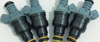
4) 4 high-resistance electromagnetic injectors. Either 4 low-resistance injectors with a peak and hold driver, or 4 low-resistance injectors with resistors in series (not recommended).
5) Throttle position sensor
6) Idle Speed Control (cannot be used with 4 throttle engines). Stepper (GM) or torque (BOSCH).
7) VAZ 2112 ignition module.
Phase sensor.
9) Knock sensor.
If January-5 is used to control the ignition in a carburetor engine
:
1) Crankshaft position sensor
2) Coolant temperature sensor.
3) Absolute pressure sensor
4) VAZ 2112 ignition module (or two-channel switch with coil).
5) Knock sensor.
Determining the position of the crankshaft.
The January-5.1 system only works with a certain reference disc of the crankshaft position, the so-called 60-2 (a wheel with 60 teeth of which 2 are missing). An _inductive_ crankshaft position sensor must be installed in the plane of rotation of the wheel; the use of other sensors operating on the inductive principle is allowed. Hall effect sensors are not permitted. It is recommended to use the VAZ 27.3847, Gas 3110 (406 engine) sensor. When installing, MUST adhere to the following rules:
— The axis passing through the center of the sensor must lie in a plane rotated 90 degrees relative to the axis of rotation of the disk! Parallelism of the axes of the sensor and the disk is not allowed. (The sensor should be located on the radius and not at the end).
— The angular position of the disk must be set and recorded with an accuracy of at least 2 degrees. The angular position is set as follows. The first tooth of the disk is considered to be the tooth that is located immediately after the 2 missing teeth numbers 59 and 60 in the direction of rotation. For installation, the engine is set at TDC of cylinder 1 according to the standard marks with mandatory control using a probe inserted into the spark plug hole - as accurately as possible. In this case, the sensor should be located opposite the center of the 20th tooth in the direction of rotation of the DPKV disk.
— The minimum thickness of the tooth (disc) is 4 mm.
— The sensor disk gap of 0.3-0.5 mm must be checked with a feeler gauge after final installation of the sensor; the gap selection is carried out by filing the bracket.
— The maximum permissible axial and radial runout of the reference surface of the disk is 0.1 mm. If, after starting the engine, a visible beating is visually observed, the disc must be redone!
— The sensor bracket must be quite massive, securely fixed to the engine at least 2 points and made of non-magnetic material (D16T, silumin, composites).
— The reference area can be applied to any standard crankshaft pulley, provided that it is made of cast iron or steel and has the required thickness, and is located outside the engine oil sump. The application is made by milling 60 grooves in increments of 6 angular degrees using a finger cutter of the appropriate diameter on a rotary table. The diameter of the cutter is calculated as follows: D*3.14/120 where D is the diameter of the disk. The recommended milling depth is 1.2 times the cutter diameter. Subsequently, having installed the disc on the car and installed the sensor, use a felt-tip pen to mark 2 teeth for removal in the place that determines the above-described requirement for the relative position of the disc and the sensor. Then the disk is removed and the teeth are removed manually using a grinder or file
— On some engines (renault, ford), the best way to make a disc is to weld a pre-made steel ring with teeth to the standard (steel) crankshaft pulley.
Separately, it should be noted that the 60-2 reference discs installed in the crankcases of some VW engines (for example ABF) do not meet the requirements of the January-5.1 control system (incorrect angular position, insufficient tooth height, inability to correctly set the gap, sensor in cast iron) and cannot be used with the January-5 control system!
In certain cases, it makes sense to install a VAZ-2112 disc on the engine by making a hub adapter and installing a serpentine belt on the generator.
If you encounter any difficulties in manufacturing the disc and bracket, you can purchase them from DTT Motorsport.
DF - Phase sensor.
The phase sensor is not mandatory for the operation of the control system, but in some cases its use is necessary.
In particular, on turbocharger engines or engines with injectors over 300cc, installation of a phase sensor is required to ensure normal fuel supply at idle and low loads. Because in XX modes, fuel supply may require very short injection times (less than 1.6 ms), which physically cannot be provided by injectors. The injectors have ranges in which it is impossible to regulate the composition of the mixture, for example, when Tinj>1.6ms the mixture is very rich and the spark plugs flood, and when Tinj<1.6ms the injectors do not have time to open at all, fuel is not supplied and the engine stops.
The phase sensor allows you to switch from pairwise parallel injection to phased injection, while the injectors open 2 times less often and, as a rule, all such problems are eliminated. Although with high-resistance injectors of 700 cc or more, there are areas where problems cannot be resolved in this way.
The phase sensor operates on the Hall effect. The DF can be made in the form of a curtain installed on the intake camshaft with a slot rotating in the gap of the sensor or a pin passing by the sensor. For VW engines and some Ford engines, DF can be obtained, for example, by altering the standard distributor.
The phase sensor can only be installed on a fully assembled engine. Phasing the DF disk by angle can only be done with the DPKV and its disk correctly installed. It is recommended to use a VAZ-2112 (curtain) or 2111 (pin on the shaft) phase sensor.
To install the VAZ-2112 phase sensor:
1) Make a ring or disk from steel 0.5-1mm thick and install it on the camshaft pulley so that it does not interfere with the belt. Secure with M4 bolts, then drill holes in the pulley and cut threads. The disc should not have any slots at all.
2) Make a bracket for the phase sensor and install it together with the sensor, so that the disk rotates in the slot DF.
3) Assemble the engine without the top cover with the timing belt (chain). (except for VW 16V engines).
4) Rotating the crankshaft, install tooth number 1 of the DPKV reference disk (60-2) with its apex opposite the crankshaft position sensor.
5) The intake valves in the first cylinder must be at the end of the intake phase (the cam has passed the pusher - the valve is closing or is already closed). If this is not the case, the crankshaft rotates 1 full revolution (360 degrees). (On VW 16V engines, the intake cam of cylinder 1 can be observed simply by opening the oil filler cap. It should be directed towards the center of the engine and slightly downwards).
6) Mark on the disk with a felt-tip pen a range of 45 degrees to the left and right of the center of the phase sensor. After this, remove the disk and remove the metal between the marks, so that the sensor in this engine position is in the middle of the resulting window.
7) Finally install the sensor and connect +12v from the main relay (37 ECU pin) to ground (14 ECU pin) and signal (8 ECU pin). To connect, use a shielded cable (2 wires in the shield, for example a microphone cable), with the ground running across the shield.
Converting a standard distributor into a phase sensor using the original Hall sensor from the distributor:
1) Disassemble the distributor, remove the slider. Pull out the shaft with reference sectors, take the dimensions of the ring of the sector area and, having turned the standard one in a lathe, make and weld a new ring, without slots (with a margin of thickness for processing), turn it in a lathe until the factory thickness and diameter are achieved. Make sure that the resulting part rotates freely in the sensor gap.
2) In the distributor - ensure unambiguous installation of the housing on the engine by welding the grooves for the mounting studs with aluminum plates and then drilling 6mm holes into them
3) Machine out a cover that replaces the distributor cover. Choose an elastic band to seal the gap.
4) Install the distributor without a cover and set the engine position as described above. Use a felt-tip pen to mark the sector +45 -45 degrees from the center of the sensor for removal.
5) Remove the distributor, disassemble, remove metal between the marks, assemble, install, connect as described above.
Installation of DF 2111.
1) Remove the valve cover and determine the location where the sensor and pin can be installed in the camshaft. (sufficient in height and clearance between the shaft and cylinder head). Typically, a place is selected where there are no cams and bearing journals as close as possible to the end of the camshaft (between the last two cams or between cylinders 3-4).
2) On a coordinate machine, bore a hole in the cover for the sensor and a hole for attaching the sensor (for M6 thread) so that the axis of the sensor passes through the axis of one of the camshafts.
3) Set the motor to the synchronizing position as described above. Close the valve cover and use a felt-tip pen to mark a point on the camshaft exactly in the center of the hole for the DF.
4) Remove the cover and, holding the drill coaxially with the sensor, drill a hole for the M8 thread in the camshaft. Cut the thread. Screw the M8 stud onto the thread sealant. Use a hacksaw to saw off the pin so that the gap between the tip and the sensor is about 0.5-1 mm. Finish with a file if necessary
5) Install the cover and sensor.
Standard Mitsubishi Evolution 6-9 phase sensor : suitable for working with the January-5 system but requires modification of the reference:
1) Set the engine to the position of the end of the intake stroke of cylinder 1 (1st tooth of the DPKV with control of the downward direction of the intake cam of cylinder 1 with the engine oil filler neck open). Fix the position.
2) Remove the timing sensor reference from the exhaust camshaft. The benchmark has 2 curtains. One of them should be cut and welded to the second one in such a way that in this position of the reference point and +-45 degrees from this position the metal is in contact with the sensor.
(since the polarity of the EVO and 2112 sensors do not match, the synchronization position of the EVO should not be empty, but metal!).
The standard sensor installed on VAG 1.8T cars is also suitable for working with January but requires a new reference ring. To make it, do the following:
1) Remove the cylinder head cover, remove the phase sensor and its reference from the engine.
2) By rotating the CV, align the first tooth of the 60-2 disk opposite the crankshaft position sensor.
3) Check the moment “end of the intake phase of cylinder 1” using the cams of the intake camshaft. If the torque does not match, make another full revolution of the crankshaft.
4) Using a felt-tip pen on the outer housing of the DF, mark by eye the marks at 45 degrees to the left and right of the center of the phase sensor, place the sensor in place and transfer the marks to the cylinder head housing.
5) Make a shutter in a lathe - a copy of the original one, but with an intact reference part and a fixing pin, which, like the original one, ensures unambiguous installation on the camshaft.
6) Place the curtain on the camshaft and transfer the marks from the cylinder head housing to it. Select the metal between the marks in the reference part of the ring.
7) Install the curtain, sensor, and assemble the cylinder head cover.
Throttle assembly, Throttle Position Sensor and Idle Air Controller (IAC).
There are 3 options for resolving this issue:
1) The standard throttle body of your car. — It is necessary to determine the type of throttle position sensor. On older engines with BOSCH control systems, it is possible to use limit sensors (full load - xx), which cannot work with the January-5 system and must be replaced with more modern resistive sensors from the same engine, or suitable for installation dimensions (VAZ VOLGA). As a rule, it is necessary to install a VAZ IAC adapter with an IAC-21203 or a Bosch torque IAC, if such mechanisms are not installed on the car or are too old.
January does not support working with electronic throttle valves; in this case, the drive and pedal must be replaced with cable ones (from an older model).
2) VAZ throttle body (46mm). — As a rule, there are no problems with it except the need to grind the flange, but this solution is suitable for engines of relatively small volume and power. It is recommended to purchase a Chevy Niva damper (214) equipped with IAC 21203.
3) GAZ throttle valve (60mm) - Also requires the use of an external IAC.
Stepper IAC adapter GM..
If you do not have any IAC, it is recommended to use a GM stepper IAC or its Russian equivalent. When using an external stepper IAC, it is necessary to make or purchase a ready-made adapter. The finished product can be purchased at DTT Motorsport; it is an adapter specially designed for the largest available VAZ IAC - 21203-1148300-01.
Torque IAC BOSCH.
Since the beginning of 2008, the management system
January-5.1 with J5LS firmware installed supports work with BOSCH and DENSO idle torque regulators! A torque IAC should have 2 windings (3 outputs), and by default the spring should be set to 50% overlap. The resistance of the torque IAC windings must be at least 10 ohms. A similar IAC is used on Volga cars with a ZMZ-406 engine.
Other IAC options.
In some cases, it is possible to use original IACV-ISCV from Subaru Impreza WRX of different years, Toyota Celica ST205, Mitsubishi Evolution 6-9 Lancha Delta/Thema and others.
Lines to the IAC adapter GM or torque IAC BOSCH (Volga).
The adapter is connected with 2 hoses through the fittings behind the throttle and in front of the throttle, respectively. Hoses should be as short as possible! The internal diameter of hoses and fittings at the narrowest point should be as follows:
For engines 1600-1700cc minimum 8mm (recommended - 9mm)
For engines 2000cc and more, minimum 9mm (recommended - 11mm)
When using camshafts with an intake phase of 295 degrees or more, the value of each parameter should be increased by 1.5 mm.
If the diameter of the lines does not correspond to the specified one or if there are narrowings anywhere in the channels or fittings in winter, you most likely will not be able to start the engine, and the engine may have unstable idling!
In the case of using torque IAC, the diameter of the channels is selected based on the size of the IAC fittings. Sometimes you can pick up ready-made hoses from Volga.
DTOZH - Coolant Temperature Sensor.
DTOZH VAZ 2112 costs an average of 50 rubles. No cases of its failure were noticed. You can buy an original from Delphi for 250 rubles, used for example on Daewoo Espero. The DTOZh has an M12×1.5 thread - as a rule, there are 2 options, either it is screwed in instead of the standard one, or to install it you need to drill out and cut the thread in the hole in the cooling jacket.
The system also supports standard Mitsubishi EVO and Subaru WRX coolant temperature sensors.
DTV - Air Temperature Sensor.
An air temperature sensor is used when using DBP. Currently, the January-5.1 system supports 2 air temperature sensors:
Part Number 25036751 DELPHI PES (GM) 3/8 NPTF - used on daewoo espero, and Niva GM (single injection, not to be confused with the Chevy Niva). Now almost disappeared from VAZ stores but can be ordered at exist.ru
0 280 130 039 BOSCH NTC 2.5k M12x1.5 - used on some European cars and is also available for order by Bosch number. (dunfan,exit).
It is recommended to use a GM sensor, since it has better temperature measurement dynamics and is generally made more correctly. However, if you already have an M12 thread cut, it’s easier to install a Bosch sensor. If the car is equipped with a turbocharger and the dynamics of temperature changes can be high, you should refrain from using the Bosch sensor.
DBP - Absolute pressure sensor.
The absolute pressure sensor is the main load sensor in the January-5 system, on which fuel supply and ignition in the engine depend, therefore the sensor must be connected by air to the engine receiver with a separate silicone hose in which no taps or tees to other sensors and devices are allowed! To do this, drill a hole in the receiver and cut an M6 thread. The connection is made using a VAZ threaded fitting and a silicone tube of a vacuum corrector 2108. It is recommended to use a vacuum corrector hose manufactured by HORS.
It is not allowed to connect the DBP to the fittings on the throttle intended for crankcase and adsorber ventilation, since they are installed in channels with a constant flow rate and do not reflect the pressure in the receiver.
There are currently 3 sensors available for naturally aspirated engines:
Volgovsky 45.3828 (recommended).
0 261 230 004 - Bosch.
DELPHI GM 1BAR (Niva GM, Daewoo, Renault F3R).
For compressor and turbocharger engines, it is also possible to use several sensors:
Motorola MPX4250AP.
DELPHI GM - 3BAR (can be bought on ebay).
Analogue of GM 3BAR produced by DTT Motorsport. (recommended).
The line of absolute pressure sensors from AEM with numbers 30-2130-15, 30-2130-30, 30-2130-50, 30-2130-75 is supported.
DD - Knock sensor.
The sensor is installed on the block (as high as possible) or on the cylinder head between cylinders 2 and 3 using a stud. If a standard stud is not available, any other stud on the block can be used. Adaptation mechanisms allow you to adjust the sensitivity of the knock detector to a specific engine.
A BOSCH sensor 0 261 231 120, or a sensor from a VAZ 2112 can be used. Unfortunately, counterfeits of VAZ knock sensors have become more frequent lately; when purchasing, pay attention to the metal part of the sensor - it must be anodized and free of traces of rust and rough processing. If there are several knock sensors on the display case, choose based on the quality of the plastic molding and the processing of its metal part. The higher the surface cleanliness, the greater the likelihood that the sensor is original. If in any doubt, use BOSCH sensors (you can buy it, for example, by PN in Dongfang).
Ignition module.
January-5 can only operate in wasted spark mode with ignition modules equipped with built-in switches - standard for January-5 systems. Either with an external 2-channel switch manufactured by DTT Motorsport and, accordingly, a pair of two-terminal coils from a Volga or similar in parameters, or a coil from a VAZ 1600 8v.
When choosing a standard ignition module, the following factors should be taken into account: The GM ignition module (new) sold in pelvis stores in the pelvis form factor is 99% fake and will not travel more than 10 km! If you decide to take the original GM, look for a module from daewoo espero, nexia, it has not a parallel but a longitudinal arrangement of coils, although the connector is the same, it is quite expensive (about $100), but this is a real GM module - it is accordingly sold only in DAEWOO spare parts stores . ProSport and other noname modules should also be avoided. The most optimal option for a standard one is the MATE-2 plant module.
The module must be rigidly fixed to the car body, and electrical contact of the car body with the plate at the bottom of the module must be ensured. The module must be installed on a level surface! If, when tightening the remote studs, a bending moment occurs on the module, after 1000 km it will most likely have to be thrown out. The module must be installed away from elements that may heat up.
You can read about the ignition system with switches and coils in the corresponding article on the website.
Control unit selection
Only engine control units “January-5.1” manufactured by NPO Avtel with catalog numbers 2111-1411020-61 or 2112-1411020-41 are allowed.
Location of the control unit.
Since the AMP55 connector of the system is not sealed and there is always a voltage of +12V and ground on the adjacent terminals, the only option for installing the control unit and relay unit is IN THE CAR! It is prohibited to place the control unit in the air intake duct or in the engine compartment of the vehicle, even if the original ECU was placed there. To install, you need to drill a hole with a diameter of 60 mm in the engine shield of the car in the area slightly to the right of the accelerator pedal (where the engine shield is flat) and pass the control unit wiring into it so that the hole is sealed with a standard rubber band in the wiring. The wiring and block should be secured just above the hole. Since it is possible for a small amount of water to enter the interior through the wires through the rubber seal, which, if the unit is not fastened correctly, will flow down and accumulate in the connector, causing electrochemical corrosion. .
How to remove the ECU on a Lada Kalina - step-by-step instructions
In order to remove the ECU unit on a Lada Kalina, you must perform the following procedure:
- First you need to unscrew 2 screws, the location of the first is shown by the arrow. The second is at the same level on the engine side. Before doing this, you must remember to remove the terminal from the battery. After unscrewing the screws, do you need to pull the block towards the passenger door? and he must leave from there along the guides. Sometimes it happens that the wires rest against the carpet. Then they need to be corrected.
- In order to remove the connector and disconnect the unit from the wires, you first need to: pull the connector lock to the side. The latch is a bracket. I think you can easily find it on the connector.
Self-diagnosis systems
Like any computer, the Priora ECU has feedback from the user.
The driver learns about problems using signal codes, which can be seen in two ways: using an additional on-board computer connected to the diagnostic connector, and on the instrument panel after performing simple manipulations.
For self-diagnosis, you can install the following devices:
- State X 1 P Priora. A small device that is inserted in place of a standard button. Has an LED display with 3 characters. In addition to the diagnostic function using 30 parameters, it allows you to warm up the spark plugs during cold periods, independently regulate the temperature at which the cooling system fan turns on, and reset engine errors.
- Priora State Matrix. A more serious on-board computer. It is placed in place of the standard clock and has a graphic display of 128 x 32 pixels.
In addition to the functions listed on the previous computer, the device can work with gas equipment, reading gas consumption. The “Afterburner” function allows you not only to reset engine errors, but also to roll back the controller to its factory state, thereby resuscitating it. After activating this option, the “Priors” ECU mode will turn on, which was set at the factory. This bookmaker also has the ability to update the software.
Multitronics C-900. Universal on-board computer. Can be installed in different places. It has enormous capabilities both in diagnostics and adjustments. Suitable for a wide range of cars. It has a 480 x 800 pixel LCD display and the ability to change settings directly from your home PC.
Program for computer diagnostics of VAZ.
As I did, with a digital camera, we set it to macro photography, raise the flash and put our hand with the camera on the computer and take a photo, everything is clearly visible, even the dust. KKl VAG adapter for computer diagnostics: Order and do the diagnostics yourself! Another program for home diagnostics of injection cars using a KKL adapter and laptop. The functionality of this program reminded me of working with the Scanmatic scanner. Great opportunities for diagnosing various parameters of injectors. It is possible to create your own sets of parameters, which is very convenient when diagnosing various sensors. You can create a diagnostic kit for, for example, an oxygen sensor and include the necessary parameters to test it. The program also has auto-detection of the ECU, which makes life very easy when you don’t know what kind of unit is in the car.
Basic malfunctions of the ignition module 2110
Despite the fact that the ignition module on the 2110 is a fairly reliable device, the element can still fail. The most common causes of breakdowns identified during diagnosis in almost 90% of cases are:
- Using components that do not meet the parameters. These could be high-voltage wires that do not match the parameters of the module, spark plugs that can damage the ignition module itself (a large charge can break the coil), etc.
- Parts with factory defects or poor quality assembly. As a result, failure of other elements of the ignition system.
If the ignition module does not perform its functions, this is reflected in the performance of the vehicle’s internal combustion engine:
- increased fuel consumption;
- the engine stops starting;
- during acceleration (sharp change in speed), dips appear;
- unstable operation of the internal combustion engine (two cylinders do not work);
- After the engine warms up, there is a noticeable drop in power and thrust.
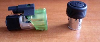
What is an ECU (brains)
The ECU - or electronic control unit on the VAZ-2112 - is the main element that is responsible for the entire cycle of transferring fuel to the engine combustion chamber system, as well as controlling its operation as a whole.
The following two tabs change content below.
About the expert:
Fan-auto
All my life I have been surrounded by cars! First, in the village, already in the first grade, I was rushing around on a tractor through the fields, then there was JAVA, then a penny. Now I am a third-year student at the Polytechnic Faculty of Automotive Engineering. I work part-time as a car mechanic and help repair cars for all my friends.
Below we will tell you how to find this part in the car and replace it.
Significant features of Lada Priora engine tuning
The main feature of chip tuning for a Lada Priora car is that it can be used to improve certain engine characteristics without the need to disassemble it.
Engine chip tuning can only be done if the car has a special electronic control unit that controls the operation of the engine system. It looks like a kind of automobile-type computer that controls the operation of the engine. The main tasks of the control unit are to provide signals to turbocharging systems, fuel injection devices and ignition systems. The computer receives this information from special sensors that determine fuel consumption, speed and other parameters.
This device has a special chip with a microcircuit on it containing programs that control the motor system. Some changes may be made to the microcircuit regarding operating parameters: marking ignition timing, amount of fuel in the cylinders, controlling the level of exhaust toxicity, etc.
Connection to diagnostic motor
The chip tuning process is carried out in two ways. The first involves dismantling an existing chip and reprogramming it after removal. After this, the chip is installed in its original place. The second way is to replace the standard microcircuit with a new one with different software.
To improve some technical characteristics of the engine, there are several methods for modifying it. For example, it is possible to increase the power ratings of an atmospheric turbocharged or gasoline power unit. The microcircuit can provide the car with economical characteristics that significantly reduce fuel consumption.
Most of the programs used by Russian manufacturers for the Lada Priora do not meet all the requirements and are rather imperfect. Therefore, individual chip tuning helps eliminate all the shortcomings present in the factory version. The new version of the program has improved algorithms for calculating the fuel mixture and the ignition timing. In addition, improvements have been made to cold start calibration and idle speed control.
Recently, it has been possible to install special systems in a car, with the help of which you can select programs for working with the engine. Their convenience is that the driver can switch the engine system to sport or economical quiet mode at any time.
Engine chip tuning is very useful for the Lada Priora car. It will be appreciated even by those car enthusiasts who do not like a sporty driving style and high speeds. It provides high-quality speed and traction performance, the ability to carry out sharp accelerations of the car when overtaking, and guarantees ease of movement even when the vehicle is heavily loaded.
ECU interchangeability on Lada Kalina
I will give a table of interchangeability of Kalina ECU
. This data was not verified by me personally, but by one authoritative master. The interchangeability of these blocks applies only to blocks with factory firmware (that is, after installation there is no need to reflash the block for your engine and sensors). So, in each line there is a block marking, firmware version and toxicity class.
- Bosch 21114-1411020-40 with software B104CR01(02) Euro3 (in my cases it was this one) can be replaced with:
- Bosch 21114-1411020-40 with software B102СQ05(CR06) Euro3;
- Bosch 11183-1411020-02 with software B101CR01(02) Euro2.
All of the above Bosch blocks can be replaced with domestic Janvr7.2 and 7.2+ blocks.
Domestic blocks are all Euro 2, with the exception of M73 blocks - they are Euro3. January 7.2 and 7.2+ blocks manufactured by Avtel or Itelma (Euro2) for Kalina 1.6l 8V: 7.2 11183-1411020-21(22) with software A(I) 201CO56(57)(58); 7.2+ 11183-1411020-21(22) with software A(I)201CP57. These blocks do not support air conditioning, as I understand it. And, in fact, the M73 blocks, which are suitable for Kalina. These units are all Euro 3: M73 21114-1411020-41 with software A303CE05(CF06) Euro3 (support air conditioning); M73 21114-1411020-42 with software I303CE05(CF06) Euro3 (support air conditioning).
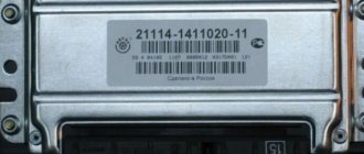
Thus, all of the listed ECUs with Euro3 toxicity class can be changed and can be changed among themselves without hesitation (only if they have factory firmware). It is also possible to replace a block with Euro 3 class with a block with Euro 2 class, but vice versa is not possible. All markings are located on a white plate glued to the ECU cover. Next, I consider it necessary to consider the option of replacing the unit with a used one that was installed on a car with an activated immobilizer, since in this case there is one unpleasant feature.
Instructions for removing and replacing the computer
The need to dismantle the ECM unit 16 of the ten valve engine arises if repairs are necessary when faults are identified. The repair process itself will depend on what exactly happened in the operation of the ECU. For example, if the contacts on the module connector have oxidized, the unit must be dismantled to clean or replace them. If the reason lies in damage to the housing, then the device must be removed for replacement; if water has gotten inside, then the module should be removed in order to dry it. Only after you have dried the block can it be tested.
If the problem lies in the performance of the board and some burnt-out elements, then you can try to repair it yourself by re-soldering some components. But we would still recommend turning to specialists for help, especially if you have never encountered such a problem before (the author of the video about repairing the control controller is Vyacheslav Chistov).
Work sequence
Before dismantling the device, you should disconnect the negative terminal from the car battery:
Do not repair the control unit if you have never had to deal with such a task before!
Getting rid of the immobilizer in Lada-2114
Having connected a new alarm system, they often encounter one problem - the autostart does not work. You need to immediately check whether all connection points are used. In the latest VAZ models, such as 2114, the ignition switch contains three terminals: starter, power, ignition. It’s difficult to get confused here, but the engine can start and stop after 5 seconds. In reality, this is how standard protection works. How to deal with it is discussed further.
We are looking for the “culprit” of all problems
Let's assume that we are talking only about the VAZ-2114 hatchback. If the key, that is, the key fob, needs to be leaned against the platform, disconnect its two connectors (the light bulb and the antenna). And then, taking a screwdriver, you can dismantle the separate block attached to the right of the steering column:
The unit itself is called APS-4, but in its case, if we talk about the last years of production, APS-6 electronics may be located.
Let's say they are installing an alarm system with auto start, and a standard immobilizer, such as APS-6, has been activated. There are four solutions:
- An immobilizer bypass is connected to the alarm, and a chip key is placed inside the bypass body;
- A good option is to install keyless crawlers, only cars of the 2114 family do not have a CAN bus, and there is nowhere to connect digitally;
- You can also switch the immobilizer to service mode, but in APS-6 modules, unlike APS-4, this feature is blocked;
- Finally, you can get rid of the standard protection completely, but to do this you will need to reset the EEPROM of the ECU.
In general, EEPROM is a “storage device”, and the ECU is the engine controller. It turns out that you will have to work with the controller unit, but the immobilizer itself will remain the same.