How to independently replace an electronic engine control unit (ECU, ECM, controller)
The electronic engine control system detects failures associated with wire breaks, short circuits to each other or to ground.
With poor contact quality in the connectors. And also with a malfunction of the sensors themselves. However, there are malfunctions in the power and ignition systems that have external signs (which are noticed by the driver), but no fault codes are recorded in the memory of the electronic unit. Main symptoms of malfunctions:
If, when starting the engine, the battery voltage drops to eight volts (determined by the voltmeter on the instrument panel), then these are poor starting conditions (low ambient temperature) or the battery capacity is less than nominal. Quite often, a voltage drop is associated with oxidation of the battery terminals. Also, starting the engine will be difficult at low temperatures and high oil viscosity.
— jerks or failures in engine operation.
When you press the gas pedal, there is no expected acceleration. A well-warmed-up engine should, when you sharply press the gas pedal, increase the crankshaft speed from low (800-900 rpm) to high (5000 rpm) in no more than 0.75 seconds.
— insufficient throttle response (power).
When the car is moving, downshifts are often used. The speed is picking up slowly. There is a feeling that the engine “does not pull, it’s dull.”
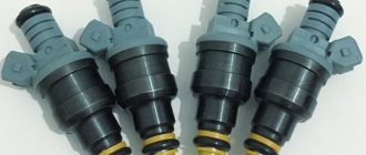
The following elements of the electronic system may be associated with the appearance of this symptom: mass air flow sensor, oxygen sensor, clogged injectors, unbalanced injectors, lack of required fuel pressure due to a malfunction of the fuel pump or pressure regulator. You should check whether the throttle valve opens fully and whether the exhaust system is clogged.
- frequent detonation.
A sharp metallic knock is heard, changing when the throttle valve is opened. The main factors contributing to the occurrence of detonation are temperature and pressure in the combustion chamber. As well as the ignition timing.
The following elements of the electronic system may be associated with the appearance of this symptom: mass air flow sensor, coolant temperature sensor, oxygen sensor, knock sensor, lack of required fuel pressure due to a malfunction of the fuel pump or pressure regulator.
The air filter should be replaced. If the filter is heavily contaminated, the correspondence between the action on the gas pedal and the signal from the mass air flow sensor sent to the control unit is disrupted.
— delays, twitching, failures.
This is most noticeable when starting off.
When you press the gas pedal, the engine does not immediately respond by increasing the crankshaft speed. Such delays can occur at all vehicle speeds.
The following elements of the electronic system may be associated with the appearance of this symptom: mass air flow sensor, throttle position sensor, injector imbalance, lack of required fuel pressure due to a malfunction of the fuel pump or pressure regulator, malfunctions in the ignition module (high-voltage wires, spark plug tips, etc.) the spark plugs themselves are faulty, the high-voltage terminals of the ignition coils are heavily oxidized).
— interruptions in engine operation.
Uneven engine operation. When the crankshaft rotation speed changes, jerking begins, especially when the load increases. There is a constant popping noise in the muffler at idle.
The correct operation of the same sensor can be disrupted by magnetization of the toothed synchronization disk (checked with a thin steel plate).
The following elements of the electronic system may be associated with the appearance of this symptom: imbalance of injectors, lack of required fuel pressure due to a malfunction of the fuel pump or pressure regulator.
- increased fuel consumption.
Tire pressure is below normal, a malfunction of the brake system (braking of one or more wheels), an aggressive driving style, all malfunctions in the engine, power and ignition systems, malfunctions in the cooling system.
— Unstable engine operation, stopping at idle.
Air leaks behind the mass air flow sensor, improper operation of the idle air control.
— pungent smell of gasoline in the exhaust system.
This phenomenon usually occurs when the working mixture is very rich, and the enrichment is associated with a misfire. It is also not recommended to idle the engine for long periods of time.
Operating principle of the controller (ECU)
Throughout the entire operation of the engine, the electronic engine control unit receives, processes, and controls systems and sensors that affect both engine operation and secondary engine elements (exhaust system). The controller uses data from the following sensors:
- DPKV (Crankshaft Position Sensor).
- DF (Phase sensor).
- MAF (instant air flow sensor).
- DTOZH (Coolant temperature sensor).
- TPS (Throttle Position Sensor).
- DK (oxygen sensor).
- DD (Knock Sensor).
- DS (Speed Sensor).
- And other sensors.
Receiving data from the sources listed above, the ECU controls the operation of the following sensors and systems:
- Fuel system (Fuel pump, pressure regulator, injectors).
- Ignition system.
- Idle speed regulator (IAC, IAC).
- Adsorber.
- Radiator fan.
- Self-diagnosis system.
Also, the ECM (ecu) has three types of memory:
- Programmable read-only memory (PROM); Contains the so-called firmware, i.e. a program containing the main calibration readings and engine control algorithm. This memory is not erased when the power is turned off and is permanent. Amenable to reprogramming and chip tuning.
- Random Access Memory (RAM); It is a temporary memory in which system errors and measured parameters are stored. This memory is erased when the power is turned off.
- Electrically reprogrammable memory device (EPROM). This type of memory can be said to be the protection of the car. It temporarily stores codes and passwords for the vehicle's anti-theft system. The immobilizer and EEPROM are compared with data, after which the engine can be started.
Description of "brains"
The VAZ 2110 is considered the first vehicle in the domestic automobile industry equipped with an injection engine. The power unit is controlled by an ECU, an electronic device that determines the basic parameters of engine operation in accordance with sensor signals. In fact, the ECU of a VAZ 2110, VAZ 2112 or any other model is the “brains” of the car, the operation of which affects the functionality of the vehicle as a whole.
Control controller in VAZ 2110
In the “Tens”, as well as the VAZ 2112, there are 16 valves and other models equipped with BOSCH 7.9.7 or January 7.2 systems, one M6 screw is installed in the head. From this screw the mass is taken to the ignition coils, and the mass is taken directly to the control model in the cabin. Typically, the mass is a welded stud mounted on the ECM bracket, particularly behind the center console, behind the left screen. In this case, the mass is transferred to the bracket through a pin, which is welded on the engine shield in the middle. It should also be noted that the nut on this stud is not usually tightened.
Control unit location
Now let's consider the location of the VAZ 2110 ECU. This device in the Ten is located under the center console, in its lower part, in particular, under the control panel. In order to gain access to the control module, you must remove the plastic panel on the passenger side, to do this you will have to use a Phillips screwdriver. Once you remove the cover, you will see many different wires, plugs, and safety devices. The controller itself is located behind them, it is screwed to the bar in a horizontal position.
The arrow indicates the location of the ECM module behind the center console
Typical malfunctions: their symptoms and causes
If the electronic engine management system malfunctions, this can lead to problems with the operation of the power unit. Unfortunately, ECU malfunctions in dozens of domestic cars are not uncommon, so the car owner should be aware of the main problems, as well as the reasons for their occurrence.
First, let's look at the symptoms of malfunctions:
As for the reasons, malfunctions in the electronic control unit can occur as a result of:
Pinout of contacts on the controller
Where is the VAZ ECU located and the interchangeability of control units
First of all, to determine the type of control unit, you need to find its installation location in the car. To do this, you should study the manual. As an example, let's look at the VAZ 2108 - 2115. On these cars, the ECU is located in the passenger compartment, on the front right, slightly below the glove compartment.
By the way, this information is also useful for computer diagnostics, since you need to know where you can connect to the diagnostic connector installed in various places on a particular model.
Diagnostic connectors VAZ 2108 - 21099 with a low panel are located near the ECU, under the glove compartment. Models VAZ 2108 - 21099 with a high panel, as well as 2113 - 2115, have a connector inside the center console. The VAZ 2108 - 2115 version with the so-called Europanel has a connector on the panel, and it is located closer to the passenger door.
- As for the units themselves, VAZ 2108 - 2115 of different years of production have different ECU models. For example, the most popular ECU January 4 was installed on early models of injection engines with central injection into the intake manifold.
Version January 5 - 6 are ECUs with distributed injection, but without oxygen sensor support. The January 7 control unit has appeared on cars since 2007, supports all sensors, and effectively controls the engine.
Let us also add that in addition to January, different generations of GM units were actively used at VAZ, being an analogy of January 4 - 7. The same can be said about Bosch or Itelma ECUs. Taking into account all the features, interchangeability is possible, but you need to select analogues that are suitable for the class, version, number of supported sensors, etc.
The fact is that each model is only suitable for a certain combination of engine and sensors, as well as wiring and firmware. This means that different models, even within the same family, can only be installed taking into account full compatibility.
Let us note once again that the types of ECUs on VAZs differ. It turns out that you cannot put January 5.1 instead of January - 4 or GM-09 SAMARA, however, for January 5.1 there is interchangeability with VS (Itelma) 5.1 or Bosch M1.5.4. In turn, the Bosch M7.9.7 ECU is not compatible with previous units, but can be replaced with January 7.2 Itelma or Avtel.
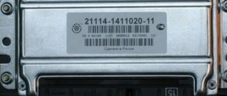
To accurately identify the ECU, just remove the instrument panel frame from the side and write down the ECU number. Also, if you have a BC, you can optionally view the version and type of the ECU, as well as the firmware number of the unit
Instructions for removing and replacing the computer
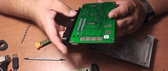
The need to dismantle the ECM unit 16 of the ten valve engine arises if repairs are necessary when faults are identified. The repair process itself will depend on what exactly happened in the operation of the ECU. For example, if the contacts on the module connector have oxidized, the unit must be dismantled to clean or replace them. If the reason lies in damage to the housing, then the device must be removed for replacement; if water has gotten inside, then the module should be removed in order to dry it. Only after you have dried the block can it be tested.
How to check the ignition of a VAZ 2110 yourself
As mentioned above, as part of ignition diagnostics, you should check the ignition module on the VAZ 2110, perform diagnostics of spark plugs, caps, and high-voltage wires. The main symptoms of malfunctions are not always associated with the ignition module, that is, you need to use the exclusion method.
To correctly determine the malfunction, it is necessary to check not only the module itself, but also other elements of the ignition system: spark plugs, caps, high-voltage wires.
Checking the spark plugs is as follows:
- unscrew the spark plugs, putting on the caps, place them on the cylinder head and crank the engine with the starter;
- if the spark on the spark plugs is not stable, replace the faulty parts with new or working ones;
- repeat the check of the new spark plugs already installed.
Please note that you cannot crank the engine with the starter with the high-voltage wires removed, as this may lead to a breakdown in the ignition module cover. Checking high-voltage wires and caps:
Checking high-voltage wires and caps:
- remove the caps, hold the wire contact through the insulator at a distance of 10-15 mm from the head;
- if the plate does not penetrate this distance, then the wires are damaged;
- check the wires for resistance (nominal resistance should be in the range from 7 to 10k ohms)
- if there are deviations, change the entire set of high-voltage wires;
You should also check the caps for breakdown. In any case, having excluded the remaining elements of the system from the list of faults, we proceed to checking the ignition module. To check it you need a multimeter and 15-20 minutes of free time.
You can perform the check yourself, knowing the sequence of work performed and the nominal value of the module. So, if there is a suspicion of a VAZ 2110 module, the check involves the following procedure:
- inspect the ignition module for chips and cracks (if any, the ignition module is immediately replaced without any checks);
- check the power supply and the presence of pulses coming from the computer (check the power supply between the engine ground and the central terminal (15) of the wire block connected to the module). The voltage when the ignition is on must be at least 12V;
- check the pulses coming from the electronic control unit on the wire block by installing one multimeter probe on the connector (15), the other first on the rightmost one, then on the leftmost one;
- having cranked the engine with the starter, use a multimeter to record short-term voltage surges (no pulses – the problem is in the ECU);
- check the resistance on the secondary windings of the coils by putting the multimeter in resistance measurement mode. At the high-voltage terminals of the module cover between terminals 2-3 and 1-4, the resistance should be within 0.5 ohms (if there is a discrepancy, the module is replaced);
- check the resistance on the secondary windings of the coil between contacts (15) and first the rightmost, then the leftmost terminal. The resistance should be 0.5 Ohm;
- check the module for a short circuit by setting the multimeter to ohmmeter mode (one probe of the device to the central terminal, the second to the metal body, the norm is no resistance);
- When the device detects any resistance, the module is changed.
Why ELM 327 does not connect to the VAZ 2110 ECU
So, why doesn't ELM327 see the ECU? What should I do so that the device can connect and see the block? Today you can find many different adapters for testing a vehicle on sale. If you buy an ELM327 Bluetooth, most likely you are trying to connect a low-quality device. Or rather, you could have purchased an adapter with an outdated version of the software.
ELM327 Bluetooth devices with outdated firmware use a different Bluetooth module that allows you to interact with two of the available six protocols. Accordingly, you can synchronize the device with a smartphone, but when you try to connect the device to the control unit, it will inform you that there is no connection with the ECU.
So, for what reasons does the device refuse to connect to the block:
If you own a device with the correct firmware version 1.5, where all six of the six protocols are present, but the adapter does not connect to the ECU, there is a way out. You can connect to the unit using initialization strings, which allow the device to adapt to the commands of the machine’s motor control unit. In particular, we are talking about initialization lines for diagnostic utilities HobDrive and Torque for vehicles that use non-standard connection protocols.
Video: ELM 327 does not connect to the VAZ ECU
What should I change it to?
Please note that if your old controller fails, you should replace it with exactly the same one that was installed previously - that is, straight from the factory. The price of such devices, depending on the type and year of manufacture of your car, can be in a wide range and range from 4,500 to 10,000 rubles .
Hello everyone, I am the proud owner of a VAZ-2112 and I can tell you a lot of interesting things about it. In particular, the ECU is also an electronic control unit, on this car model, and in principle as on basically all VAZ models, it is located in a very inconvenient place, namely under the torpedo trim on the passenger side, in order to get to it, you need to take Phillips screwdriver and go ahead.
Hello. I seem to have figured out where the ECU is located, but my question is, can it be reinstalled in a more convenient place?
The electronic control unit on the VAZ-2112 is located under the torpedo trim on the passenger side. Then all that remains is to take a Phillips screwdriver and get to it.
The site is replete with advertising. It's not pleasant to be on the page.
Video “No spark and blown fuse - repairing the ECU”
What to do if there is no spark and the fuses are constantly blowing - the video below shows the process of repairing the control controller in a garage (the author of the video is the Auto Practice channel).
I came across an article by McSystem. Actually, here it is below
In January - about Januarys. Again and in detail about the ECM-ECU masses
So, on to the topic! Classic ECM 21124 with ECU January 7.2(+) or M7.9.7 Electrical connection diagram of ECM EURO-2 M7.9.7, January 7.2 LADA 2110 with engine 21124. 21124-1411020-30, 21124-1411020-31.32
Fig. 1 ECM 21124 January 7.2, M7.9.7 Noticed, often described and characteristic problems - unstable idle speed, freezing speed, “jerking” of the engine at start and operation of the cooling fan, unreasonable jumps in the electrical parameters of the ECM during diagnostics. And this is not the entire list. And the whole problem is a rather incorrect wiring of the harness masses, not in relation to the body, but to the ECU. Therefore, in this article you will not see recommendations for tightening the “hoses” of additional mass to the ECU, due to its complete uselessness. This is not a newfangled “razmasovka” or “razminusovka”... Don’t get your hopes up!
The main idea voiced by the authors is that the wiring of the power lines of the ECU and fan and low-current sensor masses is fundamentally incorrect. Rice. 12
Fig.2 Ground connections of the ECM. S6, S7, S8
The sensors must be connected to the ground bus of the ECU board and not have contact with the body! There should be no flow of pulsed and direct currents of the ECU and IM in the sensor mass circuit. And the ECU is securely connected to the body. The rationale is to eliminate the influence of ECU currents (pulse and constant) and fan current on the reliability of sensor readings. Classic approach with data collection and processing systems! But not from AvtoVAZ designers, as usual... Now, in order
Fig. 3 Masses according to AvtoVAZ, or how not to do it
Description
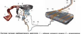
Fuel injection system diagram
1 – air filter; 2 – mass air flow sensor; 3 – inlet pipe hose; 4 – coolant supply hose; 5 – throttle pipe; 6 – idle speed regulator; 7 – throttle position sensor; 8 – channel for heating the idle system; 9 – receiver; 10 – pressure regulator hose; 11 – controller; 12 – relay for turning on the electric fuel pump; 13 – fuel filter; 14 – fuel tank; 15 – electric fuel pump with fuel level sensor; 16 – drain line; 17 – supply line; 18 – pressure regulator; 19 – inlet pipe; 20 – injector ramp; 21 – nozzle; 22 – speed sensor; 23 – oxygen concentration sensor; 24 – gas inlet of the muffler exhaust pipe; 25 – gearbox; 26 – cylinder head; 27 – outlet pipe of the cooling system; 28 – coolant temperature sensor; A – to the supply pipe of the coolant pump
Controller 2110
1 – programmable read-only memory (PROM)
The controller (Fig. Diagram of the fuel injection system) (electronic control unit), located under the instrument panel console, is the control center of the fuel injection system. It continuously processes information from various sensors and controls systems that affect exhaust emissions and vehicle performance.
The controller receives the following information:
- about the position and speed of the crankshaft;
- about engine air mass flow;
- about the coolant temperature;
- about the throttle position;
- about the oxygen content in the exhaust gases (in a feedback system);
- about the presence of detonation in the engine;
- about the voltage in the vehicle’s on-board network;
- about the speed of the car;
- about the position of the camshaft (in a system with sequential distributed fuel injection);
- about a request to turn on the air conditioning (if it is installed on the car).
Based on the information received, the controller controls the following systems and devices:
- fuel supply (injectors and electric fuel pump);
- ignition system;
- idle speed regulator;
- adsorber of the gasoline vapor recovery system (if this system is on the car);
- engine cooling fan;
- air conditioning compressor clutch (if the car has one);
- diagnostic system.
The controller turns on the output circuits (injectors, various relays, etc.) by connecting them to ground through the output transistors of the controller. The only exception is the fuel pump relay circuit. The controller only supplies +12 V to the winding of this relay.
What VAZs “think”: everything about the ECUs on the VAZ 2110-2112 and their replacement
The ECU is the main control module in any car. Thanks to the control unit, the optimal parameters for the operation of the power unit are determined, so this module must always work exactly like a clock. Where is the VAZ 2110 ECU located, what malfunctions are typical for it and how to change the device if necessary - we will talk about this below.
Let's sum it up
As you can see, by analogy with various foreign cars, VAZ injection engines of different generations are also equipped with controllers of various types. Early versions have simple solutions that are responsible for simple mixture formation and work with a small number of sensors.
We also recommend reading the article about how the automatic transmission ECU works. From this article you will learn about the features, principles of operation, purpose and breakdowns of the electronic control unit of the automatic transmission.
At the same time, more modern control units are distinguished by support for distributed injection, more flexible control of the ignition system, as well as the ability to interact with oxygen sensors, etc.
For this reason, if it is necessary to replace a VAZ ECU, it is necessary to carefully approach the selection of the control unit for replacement. Moreover, even if the blocks are compatible in terms of version, type and connectors, the firmware version must also be taken into account.
Only after all the nuances have been taken into account can you expect that the engine under ECU control will operate correctly and without failures, and the owner himself will receive stable operation of the power unit and systems, environmental friendliness and maximum efficiency from the engine in different operating modes of the car’s engine.
Description of "brains"
The VAZ 2110 is considered the first vehicle in the domestic automobile industry equipped with an injection engine. The power unit is controlled by an ECU, an electronic device that determines the basic parameters of engine operation in accordance with sensor signals. In fact, the ECU of a VAZ 2110, VAZ 2112 or any other model is the “brains” of the car, the operation of which affects the functionality of the vehicle as a whole.
Control controller in VAZ 2110
In the “Tens”, as well as the VAZ 2112, there are 16 valves and other models equipped with BOSCH 7.9.7 or January 7.2 systems, one M6 screw is installed in the head. From this screw the mass is taken to the ignition coils, and the mass is taken directly to the control model in the cabin. Typically, the mass is a welded stud mounted on the ECM bracket, particularly behind the center console, behind the left screen. In this case, the mass is transferred to the bracket through a pin, which is welded on the engine shield in the middle. It should also be noted that the nut on this stud is not usually tightened.
Control unit location
Now let's consider the location of the VAZ 2110 ECU. This device in the Ten is located under the center console, in its lower part, in particular, under the control panel. In order to gain access to the control module, you must remove the plastic panel on the passenger side, to do this you will have to use a Phillips screwdriver. Once you remove the cover, you will see many different wires, plugs, and safety devices. The controller itself is located behind them, it is screwed to the bar in a horizontal position.
The arrow indicates the location of the ECM module behind the center console
Typical malfunctions: their symptoms and causes
If the electronic engine management system malfunctions, this can lead to problems with the operation of the power unit. Unfortunately, ECU malfunctions in dozens of domestic cars are not uncommon, so the car owner should be aware of the main problems, as well as the reasons for their occurrence.
First, let's look at the symptoms of malfunctions:
As for the reasons, malfunctions in the electronic control unit can occur as a result of:
Where are the VAZ 2110 ECUs (the brains of the car)
If you are wondering where the ECU (the brains of the car) is located on the VAZ 2110, you can look at these photos where it is located ↓
Removable plastic and brains directly under the instrument panel, namely in its lower part.
In the depths of the wiring and bundle of wires and relays with fuses, you can find the controller itself, which is screwed in a horizontal position on the bar.
Instructions for removing and replacing the computer
The need to dismantle the ECM unit 16 of the ten valve engine arises if repairs are necessary when faults are identified. The repair process itself will depend on what exactly happened in the operation of the ECU. For example, if the contacts on the module connector have oxidized, the unit must be dismantled to clean or replace them. If the reason lies in damage to the housing, then the device must be removed for replacement; if water has gotten inside, then the module should be removed in order to dry it. Only after you have dried the block can it be tested.
If the problem lies in the performance of the board and some burnt-out elements, then you can try to repair it yourself by re-soldering some components. But we would still recommend turning to specialists for help, especially if you have never encountered such a problem before (the author of the video about repairing the control controller is Vyacheslav Chistov).
Tools
To replace the module, you will need:
Work sequence
Before dismantling the device, you should disconnect the negative terminal from the car battery:
Do not attempt to repair the control unit if you have never had to deal with such a task before.!
Photo gallery “How to properly dismantle an ECU”
Flashing VAZ 2110
When deciding how to flash a VAZ 2110, you can look for a specialist who will solve such issues for you, or do the firmware for the car yourself. If you decide to save money and at the same time gain a new experience by giving your car a more modern look, follow these steps. Firstly, you first need to decide on the type of firmware itself, and then find the necessary program and quickly download it from the Internet. At the same time, when deciding to flash a VAZ injector, understand whether there really is any point in installing it. Remember that if the factory options malfunction, in any case you will see an error in the data output.
Secondly, in order to flash a VAZ 2110, before installing a new program, be sure to check whether your car has factory firmware installed, which provides for disabling misfire detection. If your car has exactly this option, no further flashing will be required. In this case, determine the type of factory firmware as follows: carry out diagnostics using a scanmatic, which will programmatically show the configuration of your car’s system.
If you still need firmware for the VAZ 2110, go to specialized stores and purchase the necessary cover and DF there, and then all that remains is to correctly insert a small pin onto the camshaft. After this, connect the adapter and carefully look at its parameters, since this device must work in real time. In this case, the communication operation with the ECU should go fine; if connecting to the port gives an error, you are unlikely to be able to perform the firmware yourself.
Next, load into the ECU the program you have chosen and downloaded in advance for dual-mode firmware, for example, providing for the use of gas and gasoline, or designed to allow the use of two modes - sports and economical. After this, proceed to directly modify the ECU, carefully add a wire to its connector, providing for its subsequent grounding to ground each time the mode is switched. In order for the firmware process to proceed without incident, it is much more convenient to first remove the controller and then perform its firmware at home, correctly connecting all contacts, setting the ignition on mode, emergency power supply, programming permission and power supply to the main relay.
Probably everyone already knows that the power of even a brand new VAZ 2110 can be increased by changing the ECU firmware. This is worth doing, if only because the engine power is initially underestimated by the factory settings. The update will allow you to release all the hidden potential without replacing parts or other components.
Pinout of ECU connectors VAZ 2110 January 5.1 and Bosch M1.5.4
VAZ 2110 ECU connector
Many different ECUs were installed as standard on VAZ cars. Here are some of them:
- “January 5.1.x”, “Bosch M1.5.4”, “Bosch MP7.0”, and “VS 5.1”. They had a so-called 55-pin connector.
- “January 7.2(+)”,”Bosch M7.9.7(+)” and “M73” having an 81-pin connector.
Next, I want to give you pinout diagrams for connectors for VAZ 2110 ECUs that have a 55-pin connector
ECU connection diagram January 5.1
Step-by-step procedure for removing the ECU
- First of all, we ensure that the car is parked on a flat surface and put the handbrake on.
- Then open the hood of the car and disconnect the negative terminal from the battery.
- Next, we move into the interior and, with careful movements, disconnect the block with the wiring harness from the ECU, having previously unfastened the latch.
- Using a wrench and a “10” socket, we remove the two nuts that secure the ECU in place.
- The nuts are clearly visible after dismantling the wiring harnesses.
- When they are unscrewed, we move the bar a little to the right so that it comes out of the engagement point.
- After completing these works, you can carefully remove the ECU from its place.
- The installation procedure is carried out strictly in the same order as removal.
Poor engine start of VAZ 2110, 2111, 2112 and burnout in the power key ECU gb10nb37lz
One of the reasons for poor engine starting is the burnout of the power key gb10nb37lz in the ECU. But for some reason, many car owners immediately think that their Crankshaft Position Sensor has failed, I once had this problem. But this was also due to the fact that the wire from the sensor lay on ground and when the engine heated up, the braid melted and a short circuit occurred.
And so, our ignition diagram:
The ignition diagram of the VAZ-2110 injection engine shows the following elements -
1 – battery 2 – ignition switch 3 – ignition relay 4 – spark plugs 5 – ignition module 6 – controller 7 – crankshaft position sensor 8 – master disk A – matching device
When the car does not start, most people immediately blame the crankshaft position sensor. Changing it they realize that it didn’t help. When checking the block, the wire does not give any result. The next steps are to install a new module, or the ECU doesn’t do anything either. The car still won't start.
Everything is simple: the crankshaft sensor just has its own resistance, like the ignition module, by ringing it you can understand whether they are in good condition. Also don’t forget to check the fuse and main relay. Next, we check the spark plugs and armor wires, whether the retractor on the starter works (just put your hand on it, and if it doesn’t hit when starting up, then it’s working). During this check, you can understand what is wrong.
Checking the Crankshaft Position Sensor:
1. Connect a multimeter to the sensor terminals (in voltmeter mode with a measurement limit of up to 200 mV).
2. We quickly move the screwdriver blade close to the end of the sensor, while we observe voltage surges on the voltmeter.
Conclusion: The sensor is working.
Checking the DPKV circuit: With the ignition off, disconnect the engine management system wiring harness block from the crankshaft position sensor. We connect the tester probes to terminal “B” of the wiring harness block and engine ground.
With the ignition on and the crankshaft stationary, the tester should record a voltage of about 2.5 V.
A similar voltage should be between terminal “A” of the wiring harness block and engine ground. If the voltage values do not correspond to the norm, check the serviceability of the circuits (open and short to ground) between terminal “B” of the wiring harness block and terminal “34” of the controller, as well as between terminal “A” of the block and terminal “15” of the controller. If the voltage values do not match and the circuits are working, the controller is faulty.
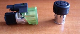
Checking the ignition module:
1. 1a-signal coming from VT3 transistor to the ECU (power switch gb10nb37lz) 2. 12 volts after ignition 3. 1b-signal coming from VT1 transistor to the ECU (power switch gb10nb37lz)
To check the resistance of the windings, you need to ring the right and middle contacts on the ignition module alternately. Both left and middle. If the module is working properly: the resistance of each winding should be around 0.8 Ohm.
We measure the resistance of windings 1-4, the winding is OK - resistance is 0.8 Ohm.
We measure the resistance of winding 2-3, the winding is PROBITED (short circuit) - resistance is 0.1 Ohm.
Conclusion: The module is faulty and needs to be replaced. Perhaps the power switch in the ECU could have burned out.
I think anyone can check the Armor of wires, and the same with spark plugs, I don’t think it’s worth describing this.
And so, we have on our hands a failed Ignition Module (The ignition module does not always clearly visually fail; it may have hidden damage. Since the module is a kind of transformer, it may have either a broken winding or a short circuit. What will disrupt the operation of the ignition system. And will cause a higher current, which will lead to the burning of the power switch.)
Interconnection diagram between the Module and the ECU:
First, let's check whether there is a control signal at the ignition module connector from the ECU. How can this be checked?
To check whether a pulse goes from the ECU to the ignition module, you can use a regular LED with a resistor (500...700 Ohm). We connect in the following order:
First, we connect the cathode of the LED to pin 1b of the ignition module connector, and connect the anode (+) of the LED to pin 15 (+12 after ignition). After connecting the LED, simply turn it with the starter. The LED should start flashing. The blinking of the LED informs us that the ECU is sending an impulse to pin 1b of the connector. We connect to pin 1a in the same way and repeat the verification procedure. If there are no flashes when you connect the LED, it means there is an open circuit somewhere in the wiring. If the LED is constantly on, this means that there is a short circuit, or the power switch (transistor VT1, VT3) has burned out and is constantly shorting to ground.
ECU repair
As indicated above, it is impossible to accurately determine whether the unit is broken based on symptoms alone. Therefore, before repairs, it is necessary to diagnose the ECU, other units, systems and sensors, and check the wiring. When it is definitely established that the cause is in the ECU and it is not software in nature, repairs are made:
- Removing the block, checking the contacts.
- Opening and external inspection of the board to detect physical faults: breaks, damaged parts, etc.
- Replacement of damaged elements, restoration of soldering, tracks and other similar work.
- Voltage measurements, diagnostics.
- Assembly and sealing.
If the problem is software related, disassembling the unit may not be necessary. In some cases, flashing the ECU or, conversely, reverting to factory settings helps. But in any case, the exact cause can be detected only after high-quality diagnostics and testing with an oscilloscope.
If you suspect that the ECU is faulty, contact our partners for diagnostics. Specialists will determine the cause of the problems and, if necessary, repair the ECU (both software and hardware). You can find your nearest ADAKT partners on the map below.
We recommend watching
Typical malfunctions: their symptoms and causes
If the electronic engine management system malfunctions, this can lead to problems with the operation of the power unit. Unfortunately, ECU malfunctions in dozens of domestic cars are not uncommon, so the car owner should be aware of the main problems, as well as the reasons for their occurrence.
First, let's look at the symptoms of malfunctions:
- There is no connection with the diagnostic tester. If problems begin to appear in the operation of the engine, the car owner can diagnose the performance of the power unit using a tester or laptop. But if the ECU does not work, then when trying to contact the on-board computer, the car owner will see that there is no connection.
- The ECM does not receive signals about the operation of the injectors, ignition system, fuel pump, valve or idle speed sensor. There may also be no signals from other actuators.
- Another sign is the lack of response to the oxygen sensor, engine temperature controller, throttle position sensor and other controllers.
- Mechanical damage to the device can also be a sign of failure. Cracks may appear on the case as a result of strong mechanical impact; radio elements or conductors could burn out (the author of the video about the repair is Pavel Ksenon).
As for the reasons, malfunctions in the electronic control unit can occur as a result of:
- Unskilled intervention. This reason is one of the most common. If a car owner independently carries out electrical repairs or installs an anti-theft system, or entrusts this work to unqualified craftsmen, errors may be made in the process.
- A common problem is lighting a car battery from a vehicle with the engine running. When lighting the engine, the engines of both cars must be turned off, otherwise there is a risk of brain damage, this is important to remember.
- Another problem that does not occur so often is polarity confusion when connecting a car battery. If you confuse plus with minus, it can not only damage the control unit, but also damage the battery itself, which can lead to expensive repairs.
- The reason may be that the battery terminals are disconnected while the engine is running.
- Also, the control unit may fail as a result of turning on the starter unit with the power bus disconnected.
- The engine control system can be damaged if an electrode accidentally hits the sensor or vehicle wiring during welding work.
- One of the most serious problems is water getting into the ECU. If liquid gets into the device, the board itself may become covered.
- A break in the electrical circuit or a short circuit in the wiring.
- The cause may also be malfunctions in the high-voltage component of the ignition system. For example, a breakdown of the ECU can be caused by a failure of the coil, high-voltage cables, distribution mechanism, etc.