To enlarge the picture, click on it
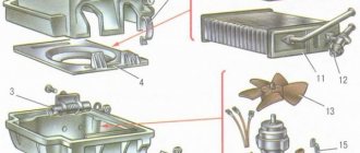
1. Heater casing mounting bracket; 2. Heater control damper; 3. Left heater casing; 4. Leg heating damper rod; 5. Radiator gasket; 6. Radiator; 7. Heater gasket; 8. Electric motor; 9. Fan shrouds; 10. Fan impeller; 11. Heating damper; 12. Heated windshield air duct; 13. Side nozzle air duct; 14. Side nozzle; 15. Central nozzle flap; 16. Blade pusher; 17. Blade axis; 18. Shoulder blade; 19. Lever for shutting off the central nozzle; 20. Windshield heating damper rod; 21. Lever for changing the direction of air flow; 22. Air heating control handle; 23. Windshield air supply handle; 24. Leg air supply handle; 25. Control lever bracket; 26. Bracket for fastening the rod shell; 27. Crane control rod; 28. Heater control damper rod; 29. Foot heating flap; 30. Axes of air heating control levers; 31. Screw clamp; 32. Heater valve; 33. Crane body; 34. Valve lever; 35. Hoses connecting the tap to the heater radiator; 36. Internal ventilation duct; 37. Windows for heating the feet of rear passengers; 38. Heater valve; 39. Driver's foot heating window; 40. Facing the central pillar; 41. Internal cavity of the central pillar; 42. Exhaust ventilation duct; 43. Center pillar upholstery; 44. Exhaust ventilation deflector lining; 45. Rubber valve; 46. Deflector housing; 47. Exhaust ventilation deflector; 48. I. Heater; 49.II. Heater operation diagram; 50.III. Heater valve; 51.IV. Exhaust ventilation of the interior of VAZ-2108 and VAZ-2109 cars.
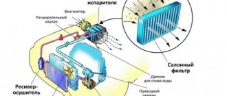
Heating of the interior is provided by air heated in heater radiator 6, which is included in the engine cooling system parallel to the main radiator. The heater is mounted in the cabin under the instrument panel with four nuts to bolts welded to the air supply box. The air heated in the heater is directed into the passenger compartment through a system of air ducts attached to the bottom of the instrument panel and through air duct 36 of the internal ventilation. The air ducts are sealed with the heater using gaskets.
The heater consists of 3 right and left plastic heater casings, which are connected along the perimeter with 1 fastening brackets. To seal the casings, a special harness is placed in the grooves.
To force air into the cabin, an electric fan is attached to the top of the heater with two screws. The design of the heater allows the electric fan to be removed from the engine compartment.
The electric fan consists of two plastic casings 9, to which an electric motor 8 type 45.3730 is attached. An electric fan impeller 10 is installed on the electric motor shaft. To obtain the required rotation speed of the impeller, there is an additional resistor, which is attached with a screw on the left side into the hole in the casing 3 of the heater. Two resistor spirals provide three speeds of rotation of the impeller.
The air heating radiator 6 is installed in the heater casings, secured with three screws to the right casing and sealed with a polyurethane foam gasket 7. The heater radiator consists of two rows of tubes, cooling plates and two plastic tanks.
The heater valve is connected to the cooling system with rubber hoses. The circulation of liquid through the radiator is carried out by the cooling system pump. The valve consists of a body 33 with two pairs of pipes. In the valve body on the supply line, a plate valve 32 of the valve with a hole for the passage of coolant is installed on the axis. The valve lever 34 is connected by a rod 27 to the lever of the handle 22 for controlling the air heating. When lever 34 is turned, the hole in valve 32 opens the line for fluid to enter the heater radiator.
The heater is controlled by three handles 22, 23, 24, the levers of which are mounted on the axes of a plastic bracket 25, which is secured with four screws to the instrument panel. The air heating control handle 22 acts through the rods 27 and 28 on the valve lever 34 and the heater control damper 2 drive lever. When handle 22 is moved completely to the right, valve 38 and damper 2 open, air will be supplied by an electric fan through the heater radiator 6, in which the heated coolant of the cooling system is circulated. In the middle position of the handle 22, the valve and damper 2 will be in intermediate positions, the air will pass both through the radiator and bypassing it. This more reliably ensures the required degree of air heating. When the handle 22 is in the extreme left position, valve 38 and heater control damper 2 are closed, and the air supplied to the cabin will not be heated.
The upper left handle 24 for supplying air to the feet of the driver and passengers is connected by a rod 4 to the damper lever 29. When the handle is moved to the left, the foot heating damper opens, air is directed from the heater casings into the windows 39 on the left and right sides to the feet of the driver and passenger in the front seat, as well as through air duct 36 of internal ventilation to the feet of passengers in the rear seat.
The handle 23 for supplying air to the windshield is connected by a rod 20 to the drive lever of the windshield heating damper 11, which blocks or opens the path for air through the air duct 12 to the glass (see heater operation diagram).
To supply air into the cabin directly to the passengers and also to blow the side windows of the car, the heater has left and right side nozzles 14 and two central nozzles. A damper 15 with polyurethane foam seals is installed in the body of each nozzle. By opening or closing the damper using lever 19, the intensity of ventilation is changed. The direction of the air flow is changed by lever 21, which allows you to rotate the nozzle with guides, as well as the blades, to the desired position.
The heater provides an average temperature in the cabin at an outside air temperature of minus 20″C in the maximum heating mode – plus 20°C, and in the footwell area – plus 25°C. Cars have exhaust ventilation that removes air from the vehicle interior. On VAZ-2108 cars, air is sucked into the gaps under the roof trim (mainly from the rear of the cabin) and enters the internal cavities 41 of the central pillars, then through rubber air ducts 42 and holes in the rear edges of the facings 40 it comes out. The suction is carried out due to the vacuum that occurs when the car moves at the rear edges of the B-pillar linings.
The device of the VAZ-2109 car heater
As mentioned above, the design of the heating system of the “nine” is quite simple. Let's look at it in a little more detail. In particular, the stove itself consists of 2 casings. They are made of plastic and connected to each other with special brackets. The designers decided to use a harness as a sealant - it is placed in the corresponding grooves of the casings. At the top of the heater there is a fan responsible for the forced supply of heated air into the car interior. It is secured with 2 screws. It should be noted that, if necessary, the fan can be removed or replaced by approaching it from the side of the engine compartment. This solution is quite convenient.
An electric motor is attached to the fan casings. Installing 2 resistor spirals will allow you to choose one of three possible rotation speeds. One point should be noted. An additional resistor is responsible for selecting the desired speed.
It is located on the left side of the stove casing and is secured with 1 screw. Finding it if necessary will not be difficult.
A radiator is installed in the stove casings; here, in fact, the air is heated, which is then supplied to the cabin. It is located on the right side. The radiator is attached to the casing using 3 screws, and the designers chose a polyurethane foam gasket as a seal. The heater consists of:
- cooling plates;
- tubes;
- 2 plastic tanks.
The design of the heater tap is also quite simple. It consists of a body and 2 pairs of pipes. The heater faucet is connected to the cooling system with rubber hoses. As you can see, there is really nothing particularly complicated here. The pump is responsible for circulating fluid in the cooling system. There is a valve located on the supply line in the valve body. It has a hole that allows coolant to pass through. You can control the air heating using the appropriate handle. This is ensured by connecting its lever to the valve through a rod. The operating principle here is as follows. After turning the lever, the hole in the valve opens the line. After this, the liquid begins to flow into the radiator along the path freed from the obstacle.
The stove can be controlled directly by changing the position of the 3 handles. Their levers are mounted on the axles of a plastic bracket, which, in turn, is attached to the dashboard with 4 screws. Let's look at how this system works. The handle responsible for controlling the heating can be used to operate the gran lever. As already mentioned, this is done through traction. This handle also adjusts the position of the damper by acting on its drive lever.
To start the process of supplying warm air to the cabin, you need to do one simple manipulation. Simply move the handle to the far right position. After this, the tap and damper will open completely, and the liquid will rush into the radiator. The fan, in turn, will forcefully supply already heated air into the car interior - however, you will have to wait a little here. Before you feel the heat, the radiator still has to heat the fluid to the desired temperature.
If you move the handle to the middle position, the valve and tap will take the “half position”. Accordingly, not the entire volume of liquid will pass through the radiator, but only part of it. In other words, you adjust the level of heating required at the moment. To completely stop the flow of warm air into the cabin, simply move the handle to the far left position. This will lead to complete closure of the valve and faucet. If you start the fan, it will no longer supply warm, but cold air into the car interior.
The upper left handle is responsible for supplying air to the leg area. Using a rod, it is connected to the damper lever. The operating principle here is also very simple. By moving the handle to the left, you open the foot warmer flap. In this case, the air from the casings will be directed into the windows. It should be noted that warm air will be supplied to the foot area of passengers sitting in the rear seat through the internal ventilation duct. The handle responsible for blowing air onto the windshield using a rod is connected to the drive lever of the corresponding damper. As in the previous case, by changing its position, you open or, conversely, close the path of air to the windshield.
Symptoms of a problem
A leak, one of the causes of which may be a faulty heater tap, is determined by two characteristic signs:
- Wet footprints appeared on the floor;
- In the cabin you can hear the characteristic smell of coolant - antifreeze or antifreeze.
Each of these signs indicates the need to inspect the condition of the unit to detect leaks in it. If the stove is not repaired in time, serious problems may soon arise, resulting in expensive repairs.
To find out who exactly is to blame for a coolant leak, lift the hood, arm yourself with a flashlight and carefully walk through all sorts of places. Since we are talking specifically about the faucet, in our situation it will be the culprit.
In addition to the faucet, hoses, pipes, and a radiator can be sources of leaks.
Features of the VAZ 2109 stove design
1. Heater casing mounting bracket; 2. Heater control damper; 3. Left heater casing; 4. Leg heating damper rod; 5. Radiator gasket; 6. Radiator; 7. Heater gasket; 8. Electric motor; 9. Fan shrouds; 10. Fan impeller; 11. Heating damper; 12. Heated windshield air duct; 13. Side nozzle air duct; 14. Side nozzle; 15. Central nozzle flap; 16. Blade pusher; 17. Blade axis; 18. Shoulder blade; 19. Lever for shutting off the central nozzle; 20. Windshield heating damper rod; 21. Lever for changing the direction of air flow; 22. Air heating control handle; 23. Windshield air supply handle; 24. Leg air supply handle; 25. Control lever bracket; 26. Bracket for fastening the rod shell; 27. Crane control rod; 28. Heater control damper rod; 29. Foot heating flap; 30. Axes of air heating control levers; 31. Screw clamp; 32. Heater valve; 33. Crane body; 34. Valve lever; 35. Hoses connecting the tap to the heater radiator; 36. Internal ventilation duct; 37. Windows for heating the feet of rear passengers; 38. Heater valve; 39. Driver's foot heating window; 40. Facing the central pillar; 41. Internal cavity of the central pillar; 42. Exhaust ventilation duct; 43. Upholstery of the central pillar; 44. Exhaust ventilation deflector lining; 45. Rubber valve; 46. Deflector housing; 47. Exhaust ventilation deflector; 48. I. Heater; 49.II. Heater operation diagram; 50.III. Heater valve; 51.IV. Interior exhaust ventilation
The stove consists of 2 plastic casings (right and left), which are connected to each other along the perimeter with fastening brackets. A special harness is placed into the grooves of the casings for sealing. The electric fan, which forces air into the passenger compartment, is secured with two screws on top of the heater. The design of the stove is made in such a way that the electric fan can be easily removed from the engine compartment.
An electric motor of type 45.3730 is attached to the fan casings, on the shaft of which an electric fan impeller with three rotation speeds is installed thanks to two resistor spirals. To obtain the required rotation speed of the impeller, an additional resistor is provided, attached to the hole in the stove casing on the left side with a screw.
The radiator for heating the supplied air is installed in the heater casings. It is attached to the right casing with three screws and sealed with a polyurethane foam gasket. It consists of:
- two rows of tubes,
- cooling plates,
- two plastic tanks.
The heater tap, consisting of a housing with two pairs of pipes, is connected to the cooling system by rubber hoses. The cooling system pump circulates fluid through the radiator. On the supply line in the faucet body, a plate faucet valve is installed on the axis, which has a hole that allows coolant to pass through. The valve lever is connected by a rod to the handle lever, which can be used to control air heating. When you turn this lever, the hole in the valve will open the line so that fluid begins to flow into the radiator. Read more about replacing the heater valve here.
Heating system elements
The stove diagram clearly shows the location of its main functional elements. It should be noted that the design of the stove on the VAZ-2108, 2109 and 21099 models is the same. Many car owners know that the heater in these models is not fully developed. As a result, the interior is not heated properly, so a decision is made to modify the stove with your own hands. Just in this case, it is important to know the design of the heater so as not to confuse anything.
The design of the stove of the VAZ-2109 car, whether it is a high panel or a low one, is absolutely identical. Therefore, the information presented will be useful to owners of this model with any instrument console.
Knowing the main points and what is located where, you can already try to independently deal with the problems that arise and fix the malfunctions that appear, while saving money and time on trips to the service station.
Features of operation and repair of the VAZ 2109 stove
Many owners of a domestic car of this brand know that the VAZ 2109’s heater does not heat well. As a result, the interior warms up poorly, and driving in such a car is not comfortable. In such cases, the stove is modified. Most often this is done within the framework of VAZ 2109 tuning with your own hands. Video and photo instructions for do-it-yourself tuning work can be found on the Internet. But sometimes it is enough to remove the VAZ 2109 stove and take it for repairs.
The operating procedure is described below.
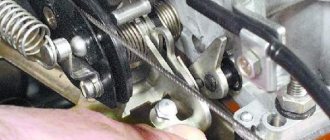
- Loosen the clamps and disconnect the two hoses from the tap pipes under the instrument panel from inside the cabin.
- Loosen the clamps and disconnect the hoses in the engine compartment from the tap pipes.
- Unscrew the nuts securing the stove faucet.
- Remove the valve from the front panel.
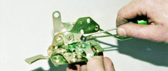
- Remove the crane rod holder.
- Disconnect the rod from the crane lever.
- Remove the cover protecting the gear shift lever from the floor tunnel lining.
- Remove the floor covering.
- Unscrew the fastening screw at the rear of the floor covering tunnel.
- We remove the floor tunnel lining with a shift back.
- We remove the internal ventilation duct and disconnect it from the stove body.
- Disconnect the wires from the heater motor.
- Disconnect the wires from the resistor.
- Unscrew the mounting nuts on the right side of the heater.
- Unscrew the fastening nuts and remove the heater along with the control panel.
After these manipulations, it is enough to choose a good workshop and take the stove there.
When the stove blows weakly, you can adjust the dampers. How to do this is shown in the video.
The radiator may be the culprit for leaving a cold heater in your car.
Instructions for replacing it are presented below:
- Open the heater valve completely and drain the coolant from the system.
- We remove the instrument panel: first disconnect the wire from the battery terminal with a minus sign, set the wheels in a straight position, disconnect the drive cable and the choke rod.
- Remove the heater control knobs, the fan switch and disconnect the trim.
- We disconnect all connectors with wires: fog lamps, exterior lighting, hazard warning lights, cigarette lighter illumination, rear window heating.
- We unscrew the screws that secure the control panel and the canopy over the instruments.
- Disconnect the fitting hose, speedometer cable and block with wires.
- We remove the devices from the panel.
- Remove the hydraulic light corrector handle and unscrew the nut that secures the headlight corrector socket.
- We remove the steering wheel and all switches.
- We take out the ignition switch with the steering column pipe.
- We remove the handle from the rod, disconnect the screws that attach the rod guide to the dashboard.
- Unscrew the screws securing the instrument panel on the left and right sides.
- We take out the panel.
- We unscrew the screw from the right edge of the stove, which secures the damper rod clamp, which is responsible for heating the glass.
- We take out the heater radiator by unscrewing the 3 mounting bolts.
- Loosen the clamps securing the hoses and remove them from the pipes.
The radiator must be thoroughly cleaned, and in case of serious problems, it is better to replace it with a new one.
Is all this necessary?
The video tag is not supported by your browser.
If the video does not play, try opening the page in a different browser.
In the video you can see the reaction of the deflectors to:
- closing the trunk door
- closing the driver's door
- turning on the 1st speed of the heater fan
- turning on 2nd speed heater fan
- turning on the 3rd speed heater fan
- turning off the heater fan
- restarting the heater fan
Ventilation and heating system VAZ 2109
As you know, on the VAZ 2109, interior heating is provided by air heated by a radiator. On the VAZ 2109, heating and ventilation of the interior are interconnected and represent a special system. In this article we will look at the general principles of operation of the heating and ventilation system of the VAZ 2109.
Heaters old and new
Finally, we note that the VAZ-21099 of different years of production used heaters with certain design features that related to the angle of the radiator and the location of the main damper.
In so-called old-style stoves (on cars before 1998), the radiator was installed almost vertically, and the main damper was located under the heat exchanger. There was a partition between the rear wall of the case and the radiator, which formed a channel that provided air supply down the case.
When the damper was open, the air flow moved through the radiator, where it was heated and supplied to the air ducts. In ventilation mode, the main damper closed the heat exchanger, forming, together with the front wall of the housing, another channel through which the flow went directly to the air ducts.
Functionality check
To begin with, especially if serious repairs are not yet in your plans, you need to try to help the damper sit in its place. Why turn on the ignition and, moving the regulator to different positions, manually move the damper, trying to “seat” it as expected.
When checking and adjusting this way, you must first remove the deflector to get to the heater damper. If you succeed, and the damper begins to move, obeying the regulator, you can consider that the half-measure was a success.
The fact is that if the socket is loose, normal operation is impossible, and over time you will still need to replace the VAZ 2110 heater damper. Therefore, you can still drive if there is such a need, but heater repair is just around the corner.
If it turns out that the damper can only be controlled manually when the ignition is turned on and the regulator is turned to its extreme positions, then the cause is most likely MMR. What often helps here is not repair, but replacement of this micromotor gearbox.
In addition, the fact that the damper does not work as it should, its adjustment does not give the desired result, can also be blamed on the microfan with a temperature sensor, as well as the control unit.
If any of the mentioned heater components fail, the best solution for the VAZ 2110 is to replace them, otherwise repairs will later require more significant investments.
What aspects to pay attention to
In what cases does the heating system of a car interior fail? What aspects should you pay special attention to?
Insufficient opening of the heating tap
The real problem in most cases occurs in VAZ cars with front-wheel drive. To check, it is necessary to compare the temperature conditions of the two pipes, namely the inlet and outlet. If there is a difference in temperature, the valve is not open enough. In order to carry out the adjustment, it is necessary to tighten the cable designed to control the valve to the maximum open state. In this case, you should carefully monitor the condition of the entire structure, since the valve is a weak point and sooner or later its switching will no longer be possible. A drastic solution may be to remove the valve from the system or install a ball valve, but in both cases there will be a problem with the easy adjustment of the fluid used to cool the interior.
Insufficient tightness of air ducts
The air that is pumped by the fan of the stove used can partially escape into the cracks. At the same time, the temperature in the car interior decreases. It is imperative to seal the connections of the entire structure, since only in this case will the optimal air temperature be maintained.
Air pockets in the radiator
Another reason why the heating regulator cannot work at full capacity is the presence of air pockets. A manifestation of the problem may be cold air coming from the deflectors. In this case, the vehicle must be placed on a hill with its front wheels, then the heater tap must be fully opened and gassed.
In 99% of cases, the switch that controls the operation of the stove can be successfully adjusted. The most important thing is to understand what principles need to be followed and how you can increase the efficiency of the heating equipment in a VAZ car.
Removal
To remove the stove, follow the following algorithm.
- Loosen the tension on the clamps and disconnect the pair of hoses from the faucet connections. To do this, you will first need to remove the dashboard from inside the cabin.
- Loosen the clamps and disconnect the hoses from the stove tap pipes. Here the work is already done through the engine compartment.
- Unscrew the heater tap mounting nuts.
- Remove the tap from the front panel.
- Remove the heater tap rod holder.
- Disconnect the rod and valve lever.
- Remove the boot that protects the gear lever.
- Remove the floor trim.
- Unscrew the floor covering fastener at the rear.
- Remove the tunnel lining on the floor by sliding it backwards.
- Remove the internal ventilation air duct and disconnect it from the heater body.
- Disconnect the wires coming from the heater motor.
- Disconnect the wiring from the resistor.
- Unscrew the fastening nuts to the right of the stove.
- Remove the remaining fasteners and remove the stove, taking the control panel with you.
Dismantling works
Further actions directly depend on your level of preparation. For beginners, it is better to take the dismantled stove to specialists. If you have a good understanding of your VAZ 2109, you can try to carry out repair work yourself.
The stove is a complex but very important component in a car. Therefore, it is always necessary to monitor its functionality and detect malfunctions in time. It is unlikely that you will want to be left without heat in the cabin in winter.
Didn't find the information you are looking for? on our forum.
Controlling the heater damper using the ESP (power window) button
In addition to mechanical control, there is also control of the heater damper from the VAZ 2110 window lifter button
Using this scheme, you can bypass the SAUO controller and control the temperature manually using the window lifter button. The price of the window lift button is 140 rubles (you must agree that it is not 1300 rubles, like the price of MMR)
We take out the heater controller and disconnect the 6-terminal and 13-terminal blocks from it.
You need to connect the ESP button according to the diagram (the pins are indicated on the back of the button):
- pin 2 to “+” from the ignition switch (via a 10 A fuse)
- pins 3.6 to “-” (5 can also be twisted here to illuminate the ESP button)
- pins 7.1 to MMR dampers
- pin 4 to + from the clock backlight (for backlighting the ESP button)
After assembling the circuit into the SAUO controller, we hook back only the 6-pin connector (responsible for controlling the fan), and leave the 13-pin connector unconnected.
All ! Now you can control the heater damper using the ESP button, bypassing the smart algorithms of the SAUO block. In the photo, the ESP button has not yet been installed in the panel. Because The 13-pin connector is not connected to the SAUO unit, it will not be illuminated. To illuminate the self-propelled gun, you can throw a “plus” from the clock backlight.
This modification of the damper control took about an hour.
To return control of the heater damper back, you don’t need to redo anything, just insert the 13-pin connector into the ACS unit.
Example, control of the ESP button for the heater damper of a VAZ 2110