Replacing the ignition coil on a Lada Kalina with an 8-valve engine yourself will take you no more than half an hour, without contacting a car service center or other workshops. To perform this work you will need a minimum of tools, namely:
- Hexagon 5 with a wrench or ratchet - the best option
- Or a regular L-shaped hexagon for 5
- 10mm wrench to disconnect the terminal from the battery
Causes of malfunction
If translated literally, “Check Engine” is an engine error, which, according to the developers, should indicate to the driver that it is worth checking this particular system. So, there are several malfunctions associated with the activation of such an alarm. Let's look at the main problems that cause a "CHECK" in the engine.
Bad fuel
Low-quality gasoline, or as it is popularly called, “bad gas,” can cause the engine warning light to appear on the dashboard. So, troubleshooting can take a lot of time and labor. In order to get rid of the effect, you will have to clean the fuel system. To do this you need to do the following:
- Remove and clean the fuel tank.
- Remove the fuel rail and wash the injectors using a special stand.
- Replace the fuel filter, because as practice shows, after low-quality fuel it becomes clogged and completely loses its service life.
Spark plug
If one of the spark plugs is damaged, Check Engine appears on the dashboard. To fix the problem, you will have to dismantle all the elements and check them for resistance, as well as visually inspect their condition. Thus, if necessary, it is worth replacing the spark plug. As practice shows, it is best to install a completely new kit, which should be pre-adjusted, check the gaps, as well as the resistance. We have already talked about the choice of candles here.
Low fuel level
When the fuel level is low, the Check Engine sign appears on the instrument panel, which may also indicate that the fuel tank cap is not closed completely and the seal is broken.
Ignition coil
The absence of a spark in the cylinders immediately signals the electronic unit, which displays the inscription “check”. This may primarily be due to the fact that the ignition coil has failed. As a rule, it cannot be repaired and must be replaced.
Oxygen sensor
A clogged lambda probe is immediately visible from the inscription on the dashboard. Here, there can only be one way out - replacement. Of course, some car enthusiasts try to clean the oxygen sensor and are quite successful, but in practice it doesn’t last long and it quickly breaks down. Therefore, it is recommended to replace it immediately.
Catalyst
The catalyst may be another reason why the Check Engine message appears on the dashboard. Usually, this is due to the high mileage of the car, so when the car starts to take oil, you should prepare for the fact that this particular part will fail. But this is not the only reason. So, bad fuel or mechanical damage will lead to the replacement of this unit.
Wiring
Cases have been repeatedly noticed that when there are problems with the explosive wire, the message Check Engine pops up. Of course, the reason should be looked for in this system and, if necessary, it is worth replacing.
ECU
The electronic engine control unit can cause a “check” to appear. Thus, accumulated errors that have not been reset for a long time may cause the dashboard to display Check Engine.
This can be treated quite simply by resetting all accumulated errors. But, as experience shows, things can get to the point where you have to change the software and flash the ECU.
The mass air flow sensor repeatedly causes the Check Engine to appear on the dashboard. In order to determine serviceability, diagnostics should be carried out. If necessary, replace this unit.
Symptoms of a bad coil
Individual ignition coils for Lada, which company is better?
There are many symptoms of coil failure and sometimes it is very difficult to determine that the coil is to blame
If such symptoms appear in your car, then you should pay attention to IKZ
Signs of coil failure:
- One of the cylinders does not work;
- The car does not develop power;
- Jerking when pressing the gas pedal sharply;
- The engine shakes at idle;
- Increased vibration at idle;
- Floating speed;
It should also be noted that if the ignition coil is faulty, misfires will appear in the cylinders, as a result of which the ECU will turn off the operation of the faulty cylinder and signal this by turning on the “Cheek Engine” lamp. When “Cheek Engine” appears on the car, it is necessary to diagnose the system. If there are misfires, the ECU will display errors 0301, 0302, 0303, 0304. Where the last digits of the codes are the cylinder number.
It is not recommended to operate a car with a faulty ignition coil; this can lead to failure of the catalyst.
2302-3-2-09-06 (Copy)
When installing the spark plug, you must screw it in by hand to avoid damaging the threads of the spark plug hole in the cylinder head.
If the spark plug does not follow the thread, strong resistance to rotation will be felt. In this case, it is necessary to completely unscrew the spark plug and, after cleaning the threads, re-tighten it.
Finally tighten the spark plug to a torque of 25–30 N. m.
Attention! Over-tightening the spark plugs can damage the threads in the spark plug holes in the cylinder head.
We replace the remaining spark plugs in the same way.
On an 8-valve engine
Ignition coil malfunction factors
Ignition coil VAZ 2106
When the first signs of a breakdown appear, inexperienced owners first of all suspect the ignition switch or high-voltage wires as the culprit. Owners of Lada Kalina with experience recommend a balanced approach to resolving the issue. How to check the fault? If the coil fails, the dashboard will remind you of this by means of an indicator light.
A voltage surge or a short circuit inside the unit can cause damage to the spark plugs. In this case, the spark will not be able to generate correctly between the electrodes.
Device failure can also be caused by the following factors:
- the car getting into an accident, as a result of which you can observe the destruction of some components of the ignition unit;
- the car was struck by lightning;
- the previously completed repairs turned out to be of poor quality;
- use by the owner of non-original components in the designated system;
- ignoring maintenance intervals.
Regardless of the reasons, the owner of the Lada Kalina should diagnose the ignition system in detail. Sometimes a problem can be generated by the influence of several negative factors at the same time. This situation warns an inexperienced driver to tend to independently search for and eliminate breakdowns, because there is a likely risk of forced failure of other known-good components.
Selected aspects of technical operation
Many inexperienced drivers, not understanding the essence of the breakdown, decide that an expensive replacement of the ignition switch or the wiring as a whole is necessary. Experienced drivers advise not to rush to conclusions. If, due to various circumstances, the ignition coil fails, the corresponding indicator lights up on the dashboard. The first thing the driver should do in such a situation is to drive the car into the garage and open the hood.
Often spark plugs fail due to a power surge or short circuit. As a result, the spark does not travel properly throughout the system. A number of other circumstances can cause a similar problem:
- the car was damaged in an accident;
- replacement of spark plugs may be required after lightning strikes the car;
- poor-quality previous repairs;
- use of non-original spare parts;
- failure to comply with technical inspection deadlines at the service center.
The ignition system can be damaged in any part of the circuit, so monitoring must be careful. It all starts with checking that the winding is properly connected to ground. It is necessary to carefully insert the contacts, focusing on the indicators of the device. Then one of the contact terminals of the device is connected to the central contact of the spark plug coil. In this case, the second contact is attached to ground.
If an infinity symbol is visible on the multimeter screen, this indicates that there is no short circuit in this area. This should tell the car owner that the ignition circuit is in perfect order. Car owners without sufficient experience in car maintenance should be guided by the following fact. If, in addition to the infinity icon, there remains a “1” on the monitor, which was there before connection, this indicates that the section is working properly.
Replacement of spark plugs may be required if there is an open ignition in the primary circuits of the module. The device is connected to the module contacts located at the edges. In this case, the stability of the indicators on the device screen indicates that there is a problem in the Kalina ignition switch
If the fault could not be detected here, then at the next stage the car owner should pay attention to the secondary winding of the module
Take a 16-cell ignition module. and rotates so that both wire ends are facing you. A diagnostic tool is connected to the terminals of the 4th and 1st cylinders. If the faults do not manifest themselves here, then it is necessary to check the 2nd and 3rd cylinders in the same way.
Procedure for removing and installing the ignition module
Which spark plugs are best for Lada Largus 16 valves?
After this, you need to disconnect all the high-voltage wires from the spark plugs; just pull them with force.
Immediately after this, we remove the wires from the ignition module itself, this is done with a simple movement of the hand, just with a little effort, pull them towards you, all four pieces one at a time.
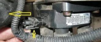
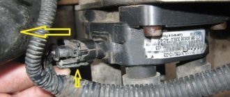
And then, we move all the wires to the side so that they do not interfere with us. And immediately remove the power plug from the module body, as shown in the photo below, by slightly pressing the latch and pulling it towards you
And at the same time, it is necessary to disconnect the plug from the knock sensor (since they are located on the same wiring harness), so that nothing unnecessary interferes with us during dismantling.
- We move the winding to the side, you can hook it to the cooling fan, then it definitely won’t interfere.
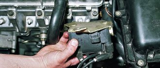
- Now we need a 5-point hex to unscrew the 4 bolts securing the ignition module housing, three of which are in plain sight, but the fourth is under the module at the bottom.
When all 4 bolts are unscrewed, you can safely remove the ignition module and install a new one in its place, if necessary. Please note that high-voltage wires must be connected in strict accordance so that the numbers on the block match the numbers on the wires.
The cylinder numbers on the wires look like the photo below:
We carry out installation and replacement in the reverse order, and do not forget to connect the plugs to the ignition module and the knock sensor, and also put the terminal on the battery. And one more piece of advice: when removing a block, look at its markings and the numbers that are there - buy exactly the same module so that there are no problems later during dismantling.
It all started when, on the way home from work, for no apparent reason, the engine started to misfire and stopped pulling. Before this, a check light came on on the dashboard, after blinking several times. The problem was solved by stopping and restarting the engine. A few days later the same thing happened again. I decided to diagnose the car.
Diagnostics showed the following error: “misfire in cylinders 2 and 3.” After talking with service technicians and scouring the Internet, I decided to replace the spark plugs. I bought the car used with 50,000 mileage, so I can’t say how long the spark plugs lasted, but they looked normal - the gap was 1mm, there was no carbon deposits (see how to check here).
With new spark plugs, the engine began to run more stable, but after a few days the misfire error popped up again. After some more searching on the Internet, I decided to check the ignition coil and armored wires. You can find out how to do this from the car’s operating instructions; there are detailed instructions there, so I won’t give them here.
The check showed that everything seemed to be normal. What then is the reason? And the reason was this. The ignition coil (on 8-valve Kalinas) is conventionally divided into two parts, the first of which is responsible for cylinders 1-4, the second, respectively, for 2-3. Since misfires constantly occurred in 2-3 cylinders, I decided that it might be a faulty coil.
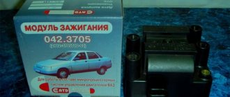
I bought a new SOATE at the store (price 500 UAH).
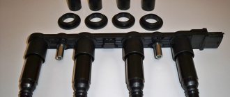
When installing, do not mix up the armor wires. They all have their own number (1, 2, 3, 4), the numbering of the cylinders starts from right to left. On the ignition coil, all terminals are also numbered:
After replacement, misfires no longer occurred. Armor wires can also cause misfires; if their resistance exceeds the norm too much, then they have become unusable and require replacement. If misfires appear in individual cylinders, then it makes sense to check the valve clearances and compression. There is also no need to ignore the injectors; they may need to be cleaned. Check the crankshaft position sensor.
Repair
Ignition module VAZ 2107
The module is dismantled and opened for repair purposes. For this you will need:
- Socket wrenches with heads 1, 13 and 17.
- Hexagon 5.
- Screwdriver.
- Soldering iron.
- Flux for aluminum.
- Stranded wire.
- Nail polish.
Opening the ignition module
Repair of the ignition module is carried out in the following order:
- On the removed device, open the case by prying it off with a screwdriver.
- Remove the silicone film covering the board.
- All aluminum is removed from the explosive contacts.
- On the board, new wires are soldered in place of all the dismantled old ones. To do this, the surface of the collector is cleaned of deposits, after which the board is heated to 180 o C (a characteristic smell will indicate when the desired temperature has been reached). During the soldering process, the ends of the wires are connected to the module.
- At the end of the operation, all contacts, the board and the module are covered with nail polish.
- The device is assembled in the reverse order, installed on the car and the engine is started. In case of normal operation, the ignition module is sealed tightly with sealant, while the wires are tucked inside the cavity so that they are not pinched at the edges by the plate.
If the device does not work, then a breakdown inside the module should be looked for more carefully. The transistor, electronic component may have failed, or there may be a break in the coil. Such a repair makes sense only if its price is significantly lower than the cost of a new part.
Checking the VAZ ignition module with a multimeter
| During operation, you have to face various problems in the operation of the engine. If the engine starts to run unstably or the traction is lost, the ignition module (MZ or coil) may be faulty. Do not rush to change it to a new one, first check it with a multimeter. |
Symptoms of a malfunctioning ignition module
- The “Check Engine” indicator is on, the on-board computer shows the “cylinder misfire” error;
- engine troits;
- the engine does not pull;
- when accelerating the car jerks;
- poor engine starting.
Ignition module wiring checks
- Disconnect the block with wires from the ignition module.
- Turn on the ignition.
- Using a multimeter in voltmeter mode, check the voltage between terminal 15 and the ground of the block with wires.
Checking the ignition module
- Using a multimeter in ohmmeter mode, measure the resistance between central pin 15 and the housing (bracket) or ring. The device should show the absence of a short circuit (the device will show a high resistance, one) of the primary winding of the coil to ground.
- We sequentially measure the resistance between pin 15 and the outermost pins 1a and 2b. The resistance of each of the primary windings of the coil should be about 0.5 ohms.
- We measure the resistance between the high-voltage terminals of the coil 1 and 4, and then 2 and 3. The resistance of the windings should be about 5.4 kOhm.
xn--2111-43da1a8c.xn--p1ai
Diagnostics of Lada Kalina wires
Before connecting high-voltage wires on Kalina purchased at a car dealership, you need to assess the current state of the car's wiring. For diagnostics, the car owner will need an analog or digital multimeter.
Before connecting the device, you need to inspect the wires for external defects. These include:
If no external damage is observed, you need to connect a multimeter. You need to check the resistance of the armor wire, so you need to switch the device to ohmmeter mode. After this, the armored wire is disconnected from the spark plug and ignition coil. The ends of the wire are connected to the contacts of the multimeter, after which the device will show the current resistance level.
Data on normal resistance values are applied to the insulating layer. For passenger cars, normal values are in the range of 4-10 kOhm. In this case, on one specific car, the data values for individual wires should not differ by more than 2.5-3 kOhm. If this threshold is exceeded, then there is a problem in the ignition system.
There are several ways to check the functionality of the wiring without using measuring instruments:
- Use of additional insulated wire. You need to strip both ends of the additional wire. Short one end to ground, and run the other bare end along the caps, joints and the entire contour of the wire being tested. If there is a defect, the tester wire will give a spark;
- You need to drive the car into an unlit box, open the hood, and start the engine. If there is a breakdown in the VP insulation, the damaged area will spark.
The easiest way is to take a working high-voltage wire and test it on each cylinder by elimination.
How to remove the ignition switch: advice from professionals
- chisel with good sharpening;
- hammer;
- flat-head screwdriver;
- pliers.
- you need to disconnect the negative terminal from the battery;
- remove the switches located under the steering wheel;
- using a small sharp chisel and pliers, unscrew the bolts securing the Kalina switching mechanism;
- remove the released bracket and the ignition switch from the steering column;
- Use a screwdriver to pry up the clamp with the wires going to the APS coil and disconnect it from the unit;
- disconnect the contact block from the common wiring harness.
- The steering column cover can be removed by unscrewing 7 screws using a Phillips screwdriver: 2 on the left side, 2 on the right, 3 on the bottom. Then you need to pull down the adjustment lever and lower the column. Both halves of the casing can be easily removed.
- To remove the steering column switches, simply squeeze the clamps and remove them from their landing spots.
- The bolts for securing the Kalina lock usually come with the head cut off during tightening. Therefore, they are unscrewed with a small chisel, applying light tangential blows. Once the bolts have moved, they can be removed using small pliers. It is better to tighten the lock with bolts with internal hexagon heads, which can be purchased in specialized stores. Such fasteners have an M6 thread, the length of the bolts is 20 mm.
- To remove the ignition switch, lightly pull the electrical wiring harness and release the connectors under the housing.
- Before installing the lock in its place, you need to insert the key into it and move it to position 1. The steering lock latch will go inside the lock. After this, you should check the functionality of the steering lock system. If everything works fine, continue installing and securing the lock and wires. If the steering shaft does not lock after a full rotation of the steering wheel, it is necessary to adjust the installation position of the ignition switch on the steering column so that the lock latch can fit into the groove located on the shaft.
- There are situations when a standard key is difficult to insert into the lock hole. In this case, you can spray WD-40 into the key hole and insert and remove the key several times. If WD-40 is not available, you can use semi-synthetic oil, which only requires one drop.
Mounting block fuse block VAZ tenth family
| without electronics | Search |
| -201212 | Search |
| required amount: 1 Voltage [V]: 12 | Search |
| required amount: 4 Voltage [V]: 12 | Search |
| Quantity: 1 Voltage [V]: 12 Number of connected contacts: | Search |
| Quantity: 1 secured with bolts/screws Number of mounting holes: 4 Number of Poles: | Search |
| SAE connector version Number of poles: 3 | Search |
| Voltage [V]: 12 Output voltage [V]: 27 | Search |
| without ignition cable Rated voltage [V]: 14 Output voltage [V]: 30 | Search |
| Search | |
| required amount: 4 Number of poles: 3 Voltage [V]: | Search |
| Mounting block (fuse block), also called a black box. If your car's electrical system suddenly stops working, then the first thing to do is check the fuses and relays. |
Fuse box diagram
- headlight high beam relay (K5);
- low beam headlight relay (K4);
- relay for monitoring and checking the serviceability of lamps (K1);
- tweezers for removing fuses;
- door power window relay;
- relay for turning on direction indicators and hazard warning lights (K3);
- starter relay;
- spare fuses;
- installation location of the fog lamp relay;
- relay for switching on windshield wipers and windshield washers (K2);
- rear window heating relay (K7);
- additional relay (K6);
- top row of fuses (F1-F10 are installed in numerical order from left to right);
- bottom row of fuses (F11-F20 are installed in numerical order from left to right)
- F1 5A License plate lighting lamps Instrument lighting lamps Side light warning lamp Trunk lighting lamp Left side side light lamps
- F2 7.5A Left headlight (low beam)
- F3 10A Left headlight (high beam)
- F4 10A Right fog lamp
- F5 30A Electric door window drive
- F6 15A Portable lamp socket Cigarette lighter
- F7 20A Electric cooling fan Sound signal
- F8 20A Rear window heating element. Relay (contacts) for turning on the heated rear window
- F9 20A Cleaners and washers for windshield, rear glass and headlights. Relay (coil) for turning on the heated rear window.
- F10 20A Reserve
- F11 5A Left side marker lamps
- F12 7.5A Right headlight (low beam)
- F13 10A Right headlight (high beam)
- F14 10A Left fog lamp
- F15 20A Electric seat heating Trunk lock lock
- F16 10A Relay-breaker for direction indicators and hazard warning lights (in hazard warning mode) Hazard warning lamp
- F17 7.5A Interior lighting lamp. Individual backlight lamp. Ignition switch illumination lamp.
- Brake light bulbs. Clock (or trip computer).
- F18 25A Glove box lighting lamp. Heating and ventilation control unit.
- F19 10A Door locking (central locking) Relay for monitoring the health of brake signal lamps and side lights Turn indicators with warning lamps Reversing lamps Generator excitation winding On-board control system display unit Instrument panel
- F20 7.5A Rear fog lamps
xn--2111-43da1a8c.xn--p1ai
How to replace the ignition module on a VAZ 1117-VAZ 1119?
Note! We want to tell you right away, remember once and for all, if you go to a car store to buy new spare parts, be sure to look at the markings on the old ones and according to it and buy new parts, for greater clarity, first find the module where it is installed in you (Where the module is installed in Kaliny was shown above in the photo), after finding it, look at the marking on the module body (indicated by a red arrow) and write it down on a piece of paper and give it to the seller in the store before purchasing the part, if you install any other module, then the same engine operation will not guaranteed since they are all different for VAZ cars!
Removal: 1) At the very beginning of the operation, disconnect the minus terminal from the battery terminal, this is done in order to protect yourself from the module, since it produces a very huge current (Around 25,000-35,000 volts) so you need to take all precautions (It produces this current, only if you start the car), and if you don’t already know how to remove the terminal, you can read the detailed instructions about this, and it’s called: “Replacing the battery on a VAZ”, read the first point in it. 2) Then, when everything is de-energized in the car due to the terminal you removed, disconnect the four ends of the high-voltage wires from the module terminals by hand and move them to the side so that they do not interfere
2) Then, when everything is de-energized in the car due to the terminal you removed, disconnect the four ends of the high-voltage wires from the module terminals by hand and move them to the side so that they do not interfere.
Note! By the way, when you disconnect the high-voltage wires, then also disconnect the wiring block from the module; for clarity, in the photo above it is indicated by a red arrow, and it is very easy to disconnect, just press the latch that secures it and then you can disconnect the block!
Custom ignition coil
This coil is installed on a 16-valve engine and is structurally different from the MZ in that it is responsible for the operation of only one cylinder. It is installed directly in the spark plug well and is put on the spark plug.
When it breaks down, the cylinder to which it is directly related fails.
IKZ device
The figure shows a cross-section of the IKZ.
The ignition coil, like the ignition coil, has two windings, a secondary and a primary, between the turns of which a metal core is placed. The coil has a rubber cap that fits onto the spark plug and prevents the spark from escaping to the side onto the engine housing.
Signs of IKZ malfunction
Below is a list of indirect signs, the presence of which can suggest that the ignition coil is faulty.
- The engine is tripping;
- Loss of power;
- Jerks when accelerating;
- Difficulty starting the engine;
- “CHECK ENGINE” lights up;
If such signs are detected, it is necessary to check the ignition coil.
Examination
The check is carried out in two stages: visual and using a device. These two methods will help you accurately verify the serviceability of the IKZ on Kalina.
Visual inspection
Visual damage to IKZ
It is necessary to remove the IKZ from the spark plug well and inspect it carefully. There should be no chips or cracks on the reel body. The resulting cracks can provoke a breakdown of the coil, which can lead to misfire in the cylinder
You should also pay attention to the rubber cap; there should be no cracks or tears in the rubber; these defects will inevitably lead to misfires and spark breakdown to the engine body
If a visual check shows that the IKZ is in good condition, you can begin checking using the device.
Checking with a multimeter
Testing with the device involves measuring the insulation resistance of the secondary and primary windings, as well as its integrity.
Ideally, the winding resistance should be as follows:
- Primary winding: tend to zero;
- Secondary winding: 300-400 kOhm;
So, let's start checking the primary winding. We set the measurement switch of the device to measure a resistance of 200 Ohms. Then we can check the error of the device; to do this, we close the probes of the device with each other and look at the readings of the multimeter; in this case, the error of the device is 0.7 Ohm (visible in the photo).
Determination of instrument error
After the error of the device has been determined, we proceed to measuring the resistance. To do this, we connect the multimeter probes to the extreme terminals of the coil (as shown in the picture (Fig. 1), pins 1 and 3) and obtain the resistance of the primary winding (in this case, 1.1 Ohm (Fig. 2)) from here we subtract the instrument error and get the desired value (in this case the coil is working).
Fig.1 (IKZ contacts) Fig. 2 (IKZ resistance frozen)
Next we check the secondary winding. We move the multimeter switch to the 2000 kOhm position. We connect the red probe of the multimeter to the coil output (to the spring), and the black probe to the middle contact of the coil input (middle contact of the connector). We get the resistance of the secondary winding, which should be within acceptable values.
Checking the secondary winding
Based on the readings received, we conclude that the IKZ is serviceable.
Checking the ICP with a spark gap
Procedure
- Disconnect the IKZ from the spark plug.
- Install a spark gap on the IKZ.
- Apply ground (from the battery terminal) to the spark gap using a wire.
- Turn the crankshaft with the starter.
- If there is a spark, then the IKZ is working.
Let us remind you that you can find a problem in engine operation by independently measuring the pressure in the fuel rail, or by checking the compression in the cylinders.
Keywords: Lada Vesta engine | lada xray engine | Lada Largus engine | Lada Granta engine | Lada Kalina engine | Lada Priora engine | ignition system for Lada Vesta | ignition system lada xray | ignition system Lada Largus | ignition system for Lada Granta | ignition system for Lada Kalina | ignition system for Lada Priora | universal article
8
Found an error? Select it and press Ctrl+Enter..
The most popular configurations of Lada Granta FL have been determined
About audio preparation of Lada Largus or how to install a radio and speakers
How to install the armrest of the rear row of seats on Lada Vesta
Removing the door trim of the Lada Granta
https://youtube.com/watch?v=4wHGBUx6x3M
How to check the serviceability of the ignition coil?
Malfunctions lead to unstable engine operation and the inability to start the car. The module's task is to generate high-voltage pulses and transmit them to the spark plug (SZ). The plus of the unit receives + 12V power from the on-board network, the minus is taken from the car body.
Ignition coil for Lada Kalina
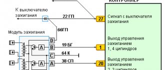
The design of the ignition module for 8 and 16 kL Lada Kalina engines includes two high-voltage transformers (coils) and two control units. One coil is connected to cylinders 1 and 4, and the second to cylinders 2 and 3. The device is connected to the SZ using high-voltage wires.
Transformers are controlled by a controller using powerful transistor valves. It receives a reference signal from the crankshaft position sensor, on the basis of which the firing sequence of the coils in the block is calculated. In addition, the controller uses information about rotation speed, coolant temperature, power unit load (mass air flow), crankshaft position and the presence of detonation. The system has no moving parts, so it does not require maintenance or adjustment.
The peculiarity of the device is that it uses a spark distribution method, which is called the “idle” spark method. The cylinders are divided into pairs. A spark is produced in each cylinder of the cylinders.
One group of spark plugs receives a spark at the moment of maximum compression of the fuel assembly (working spark), and the second at the moment of release (idle spark). Moreover, in the first case, the spark plugs are connected to the 1st and 4th cylinders, and in the second - to the 2nd and 3rd. The current in the windings of transformers constantly flows in one direction, so when sparking, the current for one spark plug flows from the side electrode to the central one, and for the second - from the central to the side.
Main signs of device malfunction:
- reduction in engine power;
- engine operation intermittently;
- intermittent idling;
- incorrect operation of paired cylinders.
If the above symptoms appear, you need to check the unit for serviceability. The cause of misfire may be the spark plugs themselves (video author - In Sandro's garage).
Before checking the operation of the unit, you should check the reliability of the connection of the high-voltage wires and the serviceability of the spark plugs. To check the motor coil of 8 or 16 cells you will need a multimeter.
Tester for verification
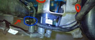
Diagnostics is carried out in several stages. First of all, the winding is shorted to ground. The multimeter must be set to check the resistance so that it works like an ohmmeter. Next, the negative probe of the tester is connected to ground - the metal part of the device body (red arrow in the photo), and the second positive probe is connected to the central contact of the transformer (blue arrow in the photo). If the resistance tends to infinity, this means that there is no short circuit and the device is working.
Checking winding short circuit
At the second stage, the primary control circuits of the coil are checked. First you need to connect the ohmmeter probes to the leftmost and rightmost terminals of the module. If the readings on the device remain the same, then there is an open circuit in the circuit. In this case, the coil needs to be replaced.
Checking the extreme conclusions
The third diagnostic stage is checking the secondary windings of the module. To check, the tester probes must be connected to the paired high-voltage terminals of the coil. First to the terminals of cylinders 2 and 3, and then cylinders 1-4, both on an engine with 16 cells and 8 cells. If the device is working properly, the ohmmeter will show a resistance of about 4 ohms, but it should not show infinity.
Checking secondary windings