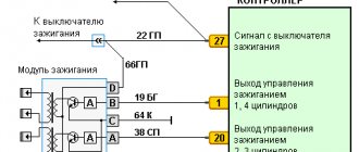
General diagram of the injector operation
So:
- there is a so-called group of information sensors, which is carried out exclusively by data collection;
- all information goes to the controller, which is the analytical center of the injection system;
- depending on a number of factors, the controller sends an electrical pulse of a certain length directly to the nozzles themselves, which open for a strictly specified time period;
- The efficiency of the cylinders and, consequently, the engine itself depends on how much fuel and air are supplied from the injectors.
VAZ 2110 injector relay diagram
The price of the injector (see VAZ 2110: flushing the injector on your own) is a flexible concept and depends on a number of components. However, the cost of fixing an injector problem at a car service center is very significant. The DIY repair instructions allow you to fix the problem, but you must have a good understanding of the injector circuit. Photos and videos - materials in this matter will become the most valuable practical assistant.
Starter problems
Many VAZ 2110 owners had a situation where the starter did not turn after inserting and turning the key. They heard characteristic clicks. This indicates that the solenoid relay is not working.
But the fact is that the “ten” does not have a starter relay, that is, an ignition relay as such. Instead, a solenoid relay works. It is supplied with a positive contact from the ignition switch. Mount this relay to the starter. It has a round shape and is approximately half the size of the starter itself.
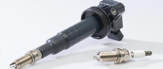
Version of the module on the 8-valve VAZ-2110
Ignition module 2111-3705010 (Stary Oskol).
Ignition module 2112-3705010 for a one and a half liter engine.
The top ten was equipped with two 8-valve engines of different sizes - 1.5 (2111) and 1.6 liters (21114). The ignition modules for these engines are different.
- The one and a half liter engine has a module with article number 2112-3705010,
- and the 1600 cc engine is equipped with module 2111-3705010.
A module for a 1.5 liter engine costs about 1500-2100, and the second one is 500 rubles cheaper.
Common breakdowns
The process of diagnosing the occurrence of problems is not any serious problem. Of course, this applies to those car owners who understand at least a little about electrical engineering and know how to use a multimeter. In the same case, if the necessary knowledge is not available, it is recommended to contact qualified specialists with experience. It is worth saying that checking the VAZ-2110 ignition coil (8 valves) using a device such as a multimeter allows you to provide the desired test result.
There is no need to rush to carry out repair work. The fact is that the problem may not lie in this element at all. Before checking the ignition module, you must consult a qualified specialist and, as a result, check the vehicle. At the same time, you will most likely spend money and your time on performing this procedure. Before checking the ignition unit, you should make sure that all other engine systems are functioning as they should.
Often, breakdowns appear in a vehicle, which subsequently disappear on their own. The indicator does not record such failures. In turn, if we talk about the controller, then they remain in it. If you try to read the errors that occur using the tester, it will not be able to detect them.
What signs of failure exist are more or less clear. Speaking about the causes of problems, first of all, they include:
- Contacts that have been contaminated.
- Quite poor mass attachment.
- The appearance of interference of an electronic nature.
Checking and adjusting the marks on the eight-valve injection valve
To adjust the ignition you will need the following tools:
- jack;
- wheel wrench;
- key (head) 10;
- key to 13;
- key to 17;
- key to 19;
- large slotted screwdriver;
- flashlight.
It is also advisable to involve an assistant.
Work order:
- We install the car on a horizontally flat surface. We block the rear wheels.
- Using a wheel wrench, unscrew the bolts securing the right wheel and jack it up. Unscrew the bolts completely and remove the wheel.
- Open the hood, use a 10 mm socket to unscrew the three bolts securing the front protective cover of the timing drive. Let's take it off.
- Using a 13mm wrench, loosen the generator belt tensioner nut and remove the belt.
- Using a 19mm wrench, unscrew the nut securing the generator pulley. To do this, you will need an assistant, whose task is to hold the brake pedal in the cabin when fifth gear is engaged. When all this is done, you will have the opportunity to see all the ignition marks of the VAZ-2110.
- We rotate the front wheel so that the lug on the camshaft gear clearly coincides with the protrusion on the rear timing drive cover. When they are aligned, take a flashlight and look at the position of the mark on the crankshaft pulley. It should point to the test point located on the oil pump cover. If they coincide, without letting go of the flashlight, we move to the engine compartment and compare the position of the marks on the flywheel crown. When the ignition is set correctly, it should also be aligned with the mark on the gearbox housing. In this case, everything is in order with the valve timing. The ignition marks are in their places. If, although the marks on the camshaft and the rear cover coincide, the tide on the crankshaft gear does not coincide with the point on the oil pump cover, it is necessary to make an adjustment.
- Using a 17 key, unscrew the timing belt tensioner pulley. We remove the belt.
- Without touching the timing shaft gears, rotate the wheel until the mark on the crankshaft pulley coincides with the marked point.
- We insert a slotted screwdriver into the inspection window so as to immobilize the flywheel.
- Carefully, so as not to change the settings, put the belt on the camshaft gear and crankshaft pulley. We tighten the tensioner pulley and fix it. Check to see if the marks have gone astray. If necessary, repeat the procedure.
How to check the ignition of a VAZ 2110 yourself
As mentioned above, as part of ignition diagnostics, you should check the ignition module on the VAZ 2110, perform diagnostics of spark plugs, caps, and high-voltage wires. The main symptoms of malfunctions are not always associated with the ignition module, that is, you need to use the exclusion method.
To correctly determine the malfunction, it is necessary to check not only the module itself, but also other elements of the ignition system: spark plugs, caps, high-voltage wires.
Checking the spark plugs is as follows:
- unscrew the spark plugs, putting on the caps, place them on the cylinder head and crank the engine with the starter;
- if the spark on the spark plugs is not stable, replace the faulty parts with new or working ones;
- repeat the check of the new spark plugs already installed.
Please note that you cannot crank the engine with the starter with the high-voltage wires removed, as this may lead to a breakdown in the ignition module cover. Checking high-voltage wires and caps:
Checking high-voltage wires and caps:
- remove the caps, hold the wire contact through the insulator at a distance of 10-15 mm from the head;
- if the plate does not penetrate this distance, then the wires are damaged;
- check the wires for resistance (nominal resistance should be in the range from 7 to 10k ohms)
- if there are deviations, change the entire set of high-voltage wires;
You should also check the caps for breakdown. In any case, having excluded the remaining elements of the system from the list of faults, we proceed to checking the ignition module. To check it you need a multimeter and 15-20 minutes of free time.
You can perform the check yourself, knowing the sequence of work performed and the nominal value of the module. So, if there is a suspicion of a VAZ 2110 module, the check involves the following procedure:
- inspect the ignition module for chips and cracks (if any, the ignition module is immediately replaced without any checks);
- check the power supply and the presence of pulses coming from the computer (check the power supply between the engine ground and the central terminal (15) of the wire block connected to the module). The voltage when the ignition is on must be at least 12V;
- check the pulses coming from the electronic control unit on the wire block by installing one multimeter probe on the connector (15), the other first on the rightmost one, then on the leftmost one;
- having cranked the engine with the starter, use a multimeter to record short-term voltage surges (no pulses – the problem is in the ECU);
- check the resistance on the secondary windings of the coils by putting the multimeter in resistance measurement mode. At the high-voltage terminals of the module cover between terminals 2-3 and 1-4, the resistance should be within 0.5 ohms (if there is a discrepancy, the module is replaced);
- check the resistance on the secondary windings of the coil between contacts (15) and first the rightmost, then the leftmost terminal. The resistance should be 0.5 Ohm;
- check the module for a short circuit by setting the multimeter to ohmmeter mode (one probe of the device to the central terminal, the second to the metal body, the norm is no resistance);
- When the device detects any resistance, the module is changed.
High-voltage wires VAZ 2115: Connection, replacement, location
Automotive high-voltage (HV) wires play an important role for internal combustion engines, since they help transmit high current from the ignition coil to the spark plugs.
The serviceability and efficiency of the wires determines the timeliness and intensity of ignition of the fuel-air mixture, and therefore the correct and uninterrupted operation of the engine.
Despite their simplicity, wires have many different “sores” and can cause a lot of troubles to their owner, which in one way or another will affect his nerves and pocket.
Table of contents
ConnectionReplacementLocation
Connection
The order of connecting high-voltage wires must be strictly sequential, since each cylinder of the engine corresponds to a specific socket on the ignition module. Considering that there is a numbering of the sockets on the ignition module body, the risk of confusing anything is minimal.
The procedure for connecting high-voltage wires of the VAZ 2114 injection type depends on the year of manufacture of your car. Fourteen cars before 2004 had 4-pin ignition modules installed, and cars after 2004 had 3-pin coils.
The connection diagram for VAZ 2114 high-voltage wires to the ignition module (until 2004) is as follows:
Connection diagram for VAZ-2114 with ignition coils (after 2004):
To correctly install high-voltage wires on the VAZ 2114, follow the following algorithm of actions:
— Turn off the ignition. Open the hood and remove the power terminals from the battery;
— We remove the old GDPs from the mounting sockets on the module and cylinders;
— We remember the location of the high-voltage wires of the VAZ 2114 and connect new GDPs according to the diagram. Before replacing, it would not be amiss to draw this very diagram by hand on paper so as not to confuse anything;
— We connect power to the battery and, to check whether we did everything correctly, start the engine.
When installing the wiring, do not try to connect individual air intakes to each other with plastic clamps; to do this, you must use the comb holder that comes with them. A thin clamp can easily wear through the insulating coating. Also make sure that the GDP does not bend.
Connecting armored wires on VAZ 2115 and 2113 is carried out in a similar way.
Replacement
How to remove high-voltage wires?
Turn off the ignition Open the hood
We pull out the wires from the ignition module and from the engine.
How to connect high voltage wires?
The BB wires must be connected in a certain order. Each wire goes to a specific cylinder and to a specific connector in the ignition module (ignition coil). There are markings both on the wires and on the ignition module. But without removing the module, the markings cannot be seen, so see the photo below.
Connection diagram for high-voltage wires:
Cylinder numbering from left to right. Ignition module numbering: first cylinder - lower left compartment of the ignition module
Second cylinder - upper left compartment
The third cylinder is the upper right,
The fourth cylinder is the lower right compartment of the ignition module.
Location
Incorrect installation and location of high-voltage wires can lead to a spark jumping from wire to wire or to ground, which, in turn, can lead to misfires and a decrease in the crankshaft speed when the car is moving at high speed.
Therefore, install the high voltage wires properly as shown in the pictures above.
Examination
EXECUTION ORDER
Disconnect the high-voltage wires from the spark plugs and ignition coils. Clean and check the integrity of the insulation of high-voltage wires. Check the internal contact surfaces of high-voltage wires for corrosion or carbon deposits.
Use an ohmmeter to measure the resistance of the high-voltage wires.
| Cylinder |
| Length, mm |
| Resistance (BOUGI), Ohm |
| Resistance (R16AIPS), Ohm |
The resistance of the high voltage wire should not exceed 10,000 ohms, otherwise replace the wire.
Malfunctions of ignition modules on the VAZ-2110. DIY diagnostics
If this does not happen, problems begin with the motor:
- power drop;
- high gasoline consumption;
- failures during acceleration;
- unstable idle speed;
- engine failure when starting.
Signs
- If one of the module coils completely fails, then two cylinders do not work. This is clearly visible even to the naked eye - the engine is feverish at idle, starting is difficult, fuel consumption is sky-high, loss of dynamics.
- To eliminate all other components of the ignition system, make sure that the spark plugs are in working order. To do this, unscrew them and check the spark on each of the spark plugs by cranking the engine with the starter and placing the spark plug with the high-voltage wire on the head so that the body (threaded part) of the spark plug touches the engine mass. If there is no spark or it is weak, replace the spark plug with one that is known to work.
- If this does not lead to anything, check the high-voltage wires. Thus, we will exclude spark plugs, caps and high-voltage wires from the list of non-working elements. Next we will check the ignition module.
How to check the ignition module?
- First of all, we carefully inspect the module body. There should be no chips, burns or cracks on its surface. A module with a damaged casing is replaced without any hassle.
- If the spark is unstable only on cylinders 1-4 or 2-3, one of the module coils is probably damaged. In any case, we will conduct a comprehensive check of the device. For this we will need a regular multimeter.
Multimeter for checking the ignition module.
Diagnostic procedure
The diagnostic procedure can be as follows:
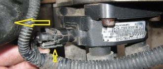
- Disconnect the connector with signal wires from the module.
- Turn on the ignition and check the voltage at terminal 15 (central) of the control wire block. The rated voltage is 12 V. A drop or absence of voltage when the battery is charged indicates that the engine control unit does not supply power to the module. This means the reason lies in the ECU.
- We remove the high-voltage wires, unscrew the module mounting bots and remove it.
- We check the resistance of the primary windings of the coils - put the multimeter in resistance measurement mode and take readings from the rightmost and central terminals, then from the leftmost and central terminals. The nominal resistance of the primary windings is approximately 0.5 Ohm.
- We measure the resistance of the secondary windings between terminals 1-4 and 2-3 high-voltage wires. Nominal value: 5.4 kOhm. If the readings do not correspond to the nominal value, the coil is not working correctly.
- Check the module for a short circuit. To do this, install one tester probe on the central pin 15, the second on the metal body. The device should show the absence of a short circuit (one or infinity). Otherwise, one of the coils has shorted to the housing.
Errors
A module malfunction can also be determined using an error scanner. Error codes associated with the module are:
- R-3000, R-3001, R-3002, R-3003 and R-3004 - gaps in sparking, the module itself, spark plugs, high-voltage wires or the ECU may be to blame;
- R-0351 - the coil of cylinders 1-4 does not work;
- R-0352 - the coil of 2-3 cylinders does not work.
It is possible that the spark plugs are not working or the high-voltage wires are broken, but if we initially diagnosed them, then the fault lies entirely with the ignition module. In this case, we can repair it ourselves, or buy a new one, which is faster, easier and guarantees uninterrupted operation of the ignition system. Good luck to everyone, strong spark and good roads!
How the device works
Instead, an ignition module is used, consisting of high-energy control electronics and two coils. The advantage of the new system is that it does not require regular maintenance and maintenance, since there are no moving elements. Also, no special adjustment of the system is required. The reason lies in the presence of a controller. is the one responsible for setting up and adjusting.
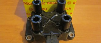
The process of checking all ignition coils on a VAZ-2112
The VAZ-2112 engine with 16 valves uses individual Bosch ignition coils and in order to check them, the following procedure must be followed:
First of all, we remove each coil from its landing well.
Then we turn off the power supply and remove them all together as an assembly. First of all, we pay attention to its external condition, the absence of cracks and various breaks.
The same applies to the spring located inside the coil, look at its position, it should be exactly in the center.
Despite the fact that many people on the Internet talk about the impossibility of checking a coil with their own hands, it is possible to check it only by knowing their initial values, which are measured in ohms.
- In order not to make false measurements, first of all we check the internal resistance of the wires and the multimeter itself. To do this, switch the device to the OM position and connect the probes to each other. What value the multimeter gives is its internal resistance. The value can range from 0.0 to 0.3 ohms.
- First of all, we “ring” the primary winding, which is located on the first and third contacts; when connecting, the polarity does not matter.
- Depending on the presence of error readings and coil readings, we add up the final indicators. For example, if the internal resistance is 0.2 ohms and the coil value is 0.7 ohms, therefore the correct value would be 0.5 ohms. Which is the norm.
- We continue diagnostics with each of the coils.
- If it happens that there are no indications, then we once again check the quality of the connections and the correctness of the connection. If the readings are still zero, then the primary winding on this coil is faulty.
When the readings on the primary winding on all coils are correct and show their values, we proceed to checking the secondary winding.
To do this, set the switch to 2000 kOhm mode. Next, we place the multimeter probe on the coil, observing the polarity, black to pin 2, which is located exactly in the middle of the connector, and the red probe to the spring, inside the rubber plug. Three-digit values will mean the coil is working properly, and infinity values will indicate its failure.
Please note that if you cannot measure the resistance correctly the first time, you can wipe the fixed elements from dirt and deposits, since dirty parts can interfere with the signal output. When replacing old coils with new ones, you should strictly use analogues, taking the faulty part with you to the store in advance.
Operation of the contactless ignition system
- By turning the ignition key, current from the battery is supplied to the mounting block.
- From it, low voltage current passes to the coils, starter and other electrically dependent devices of the system.
- The starter begins to turn the engine. At the same time, the transistor switch receives a signal from the pulse sensor.
- The commutator interrupts the current on the primary winding of the coil, which allows you to create a high voltage current on the secondary winding.
- The resulting current goes to the central terminal of the coil and enters the distributor.
- Depending on the position of the crankshaft, current is transmitted through high voltage wires to the corresponding spark plug.
- The current produces a spark charge that ignites the fuel-air mixture.
Diagnostics and testing of the ignition coil of a VAZ 2106
How to check the ignition coil of a VAZ-2106 car at home? The best way is to use a multimeter or ohmmeter. Winding testing using this equipment is carried out as follows:
- to make sure that the primary winding is in good condition, connect an ohmmeter to its side terminals and look at the resistance readings. For a fully working ignition coil, it should be at least 3-4 ohms. Otherwise, the device will need to be repaired or replaced;
- to check the secondary winding, one of the ohmmeter outputs is connected to the same side one, and the second one is connected to the central terminal on the pulse transformer itself. The normal value is somewhere in the range of 7.5-9.2 ohms. To get accurate data, it is better to consult your vehicle's owner's manual. If there are any deviations, the ignition coil must be replaced.
Before performing the checks described above, you must disconnect the negative terminal from the battery. This will help eliminate the risk of short circuit
Diagnostics and testing of the ignition coil of a VAZ 2106
Checking for spark
Checking the spark is possible using several methods: to ground, using a multimeter, or a special tester on a piezoelectric element. The first method is the simplest. The body of the unscrewed spark plug is brought to the metal (usually the engine cylinder block), after which the engine is cranked by the starter and the presence of a spark is analyzed.
Please note that this verification method cannot be used when diagnosing injection cars. The fact is that a car with an injector has an ECU and other electrical equipment that is quite sensitive and can be damaged
The photo shows checking the spark plug on a VAZ 2106
The second method allows you to better assess the condition of the spark plug, identify breakdown, etc. The use of a special tester is a method of checking the spark on injector cars, reminiscent in its principle of checking by analyzing the spark breakdown to ground (the first method). In this case, the risk of burning the control unit is minimized. Now let's talk about how to check the spark on a fuel-injected engine.
Checking the secondary winding
The secondary winding of the coil is checked in almost the same way, only one of the ohmmeter wires needs to be connected to the side terminal, and the second to the central one on the coil. Everything is demonstrated below:
Here the resistance data is completely different and during normal operation it should be in the region of 7.4-9.2 kOhm. Judging by the readings of the device, my case shows and confirms again that everything is fine with the coil.
The photo shows a check of the secondary winding of the ignition coil of a VAZ 2106
To avoid any misunderstandings, I want to warn you that the figures given in this article apply to a greater extent to VAZ 2106 type B117-A ignition coils, although on many models the parameters are identical. But still, for your modification, it is better to look at the data in specialized sources.
If, as a result of the check, it turns out that the element is faulty, then it is necessary to replace it with a new one.
Checking the distributor
If the coil is working properly, but the engine does not start, the problem must be looked for in the distributor; to do this, you need to remove its top cover by unfastening 2 latches. The inside of the cover must be carefully inspected; all contacts and the ember must be intact. You need to remove the slider from the distributor and also inspect it from the inside; it happens that it cracks and a spark hits ground.
Photo: Checking the VAZ 2106 distributor
Next, you need to carefully inspect the breaker contacts and, if necessary, clean them with fine sandpaper. You also need to inspect the capacitor, which is usually screwed to the distributor; without it, there will be no spark either. To test the capacitor, you need to apply power to it from the battery, and then connect a light bulb or short-circuit the contacts with a metal object. If the light does not blink and there is no spark when it closes, the capacitor is faulty. It can be replaced by any other, but not polar.
In conclusion, I would like to note the fact that you should never check the spark for the gap from the wire to the engine; in this case, the ignition coil quickly fails and the VAZ 2106 will no longer be able to start without replacing it. All this happens because the coil is punctured from the inside, and all because of the very large gap for breakdown.
First signs of trouble
The main signs of ignition coil failure are lack of ignition. If it is a single device with a distributor, then in all cylinders; if it is a double or single device, then in those served by it. The absence of a spark is not necessarily a 100% sign of a faulty coil. Perhaps the limiting resistor has burned out, the spark plug is faulty, the high-voltage wire has broken, or there is a malfunction in the ignition system. A comprehensive fault diagnosis is required.
Visual signs that the ignition coil is not working:
- the presence of “breakdown tracks”, oxides on the coil;
- change in dielectric color;
- burning of contacts and connectors;
- traces of overheating on the body;
- increased pollution.
Let's talk in more detail about these and other points indicating that the ignition coil of the VAZ 2106 is in a faulty state.
Presence of interruption tracks in the ignition coil
Let's figure out why the ignition coil breaks. Firstly, over time, as a result of high temperature changes, the dielectric insulation cracks, and salty moisture, which is a conductor, can enter microcracks.
The photo shows a common malfunction - breakdown of the ignition coil of a VAZ 2106
For voltages of more than 15,000 volts generated in the secondary winding, even pure undistilled water acts as a conductor. Secondly, during operation, the physical properties of the dielectric and rubber insulation of the tips of high-voltage wires, especially those of dubious production, change.
High-voltage breakdown can be caused by the installation of non-standard high-voltage wires in which there is no distributed current-limiting resistance. A breakdown can occur as a result of severe contamination or waterlogging. Even in the event of a single breakdown, irreversible changes occur in the structure; further operation is not recommended.
Burning of contacts and connectors of the ignition coil of a VAZ 2106
The big disadvantage, the disadvantage of CG, is the sparking process, which cannot be eliminated in any way. However, significant minimization of sparking can be achieved by connecting a capacitor. Yes, and be sure to set the correct gap.
Experts say that if you increase the gap above standard values, you can get rid of sparking. In other words, if the distributor contacts are burning, increasing the gap will be the optimal measure to eliminate the problem. However, this also has its drawbacks. In particular, the angle decreases, which leads to a decrease in the additional current voltage.
Traces of overheating on the ignition coil body of a VAZ 2106
Another sign by which you can determine the malfunction of the ignition coil of the VAZ Six is the presence of traces of overheating on the short circuit housing. The photo shows what they look like:
This is what signs of overheating look like on the ignition coil housing
Let's sum it up
As you can see, the VAZ 2110 ignition module is a fairly simple device consisting of contacts, coils, boards and wires. However, only contact connections can be repaired. Other elements are beyond repair and need to be replaced.
At the same time, before starting repair work, it is necessary to properly test the module. To do this, you should adhere to the general rules, and also take into account the subtleties and nuances discussed above. As a result, diagnostics of the VAZ 2110 ignition module allows you to quickly identify certain problems and eliminate problems.
Symptoms of a problem
It is extremely rare for two built-in coils to fail at once, so it is more likely to be possible to start the engine with a faulty unit. However, even an inexperienced driver will immediately suspect something is wrong. The malfunction will appear as follows:
- unstable (floating) idle speed;
- the engine has difficulty picking up speed;
- characteristic sound of the engine (triple);
- jerking when accelerating (while moving).
Operating a car with such a breakdown is possible (you can drive to a garage or car service station), but it is not advisable unless absolutely necessary.
Similar signs of unstable engine operation are possible with a number of other ignition or fuel supply faults. To differentiate possible breakdowns, the performance of the ignition unit should be determined. It would be useful to check the contacts of the wires coming to the device, as well as their integrity.
Methods for diagnosing device performance
The simplest method that will help determine the performance of the coil is to replace it with a similar working device. This is possible if there is somewhere to get it. Please note that the module must match the parameters of the device under test. If the engine with a working coil works as before the breakdown, the ignition module is definitely faulty.
The main testing method involves using a multimeter. It consists in determining the resistance of the secondary windings of the coils built into the ignition module. The method is simple and does not require additional skills. The device does not need to be removed for testing. The check is done with the engine turned off.
This is how you check the resistance of the secondary winding with a multimeter
- High-voltage wires are removed from the module sockets.
- The tester switch is set to the 20 kOhm position.
- The multimeter rods are placed in turn in the recesses of the corresponding contact pairs (1 and 4, 2 and 3).
- With an intact secondary winding, the performance in both cases is the same. Normally, the resistance should be about 5.4 kOhm (in some models the indicators differ, which needs to be clarified). If the resistance is much greater, then there is a winding break. The resistance is much lower - a breakdown. The coil is faulty and cannot be repaired.
Video: How to check the secondary winding with a multimeter
When is there an option to repair?
If during testing both secondary windings show integrity and serviceability, the reason for the inoperability of the coils may be a break in the soldering of the switch wires. Such damage is detected when the rear cover of the module is removed. If you have a soldering iron and know how to use it, you can restore the integrity of damaged contacts, while at the same time strengthening the rest. This, unfortunately, is the only failure of the ignition module that can be repaired.
Testing the ignition module can be done using simple do-it-yourself instruments. Based on our advice, you will be able to fully check both the module itself and other elements of the mechanism that may be the cause of the breakdown. We wish you success in this matter!
Read with this
- Ways to independently check the ignition module
- How to remove and replace the ignition coil on a VAZ-2114 with your own hands
- Purpose of a spark on a VAZ 2106, reasons for its absence and troubleshooting
- Contactless ignition VAZ 2106: device, operation diagram, installation and configuration instructions
- VAZ ignition coil connection diagram
- Reactive and active resistance
- Malfunctions of the contactless ignition system of VAZ 2108, 2109, 21099 cars
- Hall sensor VAZ 2108 and 2107: how to check, replacing the regulator and video
- Correct ignition adjustment on a VAZ 2107 carburetor
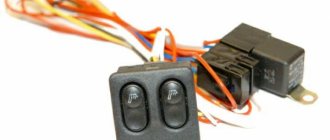
- Window regulators VAZ-2114: connection diagram. Power window button pinout