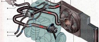
Cooling system diagram
All the main elements are described below.
1 – heater radiator; 2 – steam removal hose of the heater radiator; 3 – outlet hose; 4 – supply hose; 5 – coolant temperature sensor (in the block head); 6 – pump supply pipe hose; 7 – thermostat; 8 – filling hose; 9 – expansion tank plug; 10 – coolant level indicator sensor; 11 – expansion tank; 12 – exhaust pipe; 13 – liquid chamber of the carburetor starting device; 14 – radiator outlet hose; 15 – radiator supply hose; 16 – radiator steam outlet hose; 17 – left radiator tank; 18 – sensor for turning on the electric fan; 19 – fan electric motor; 20 – electric fan impeller; 21 – right radiator tank; 22 – drain plug; 23 – electric fan casing; 24 – timing belt; 25 – coolant pump impeller; 26 – supply pipe of the coolant pump; 27 – coolant supply hose to the throttle pipe; 28 – coolant drain hose from the throttle pipe; 29 – coolant temperature sensor in the outlet pipe; 30 – radiator tubes; 31 – radiator core.
Cooling system components
Now that you know the entire diagram of the VAZ-2112 cooling system, you should learn about all its main details in more detail:
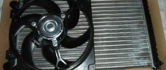
Cooling radiator
Copper cooling radiator
The radiator is designed to cool the fluid in the system as it passes through it in the so-called “great circle” . It is made of aluminum, has a tubular-plate, two-pass design, and is equipped with plastic tanks, one of which has a special partition designed to allow coolant to pass through. The liquid to pass through the “large circle” flows through the upper pipe and exits through the lower one.
Expansion tank
This tank is quite reliable, but its connections sometimes have to be checked for leaks.
The expansion tank, made of translucent polyethylene, is designed to fill and control coolant. When the fluid in the system is completely filled, it should be in the tank between o and “MAX”. Two pipes for removing steam are built into the tank, one from the heater radiator, the other from the cooling radiator.
Expansion tank cap
Two types of expansion tank caps.
The tightness of the cooling system is ensured by the expansion tank cap, or rather by its inlet and outlet valves. The exhaust valve maintains increased pressure on a hot engine compared to atmospheric pressure, due to which the boiling point becomes higher, reducing the loss of steam.
Thermostat
The thermostat is designed to distribute coolant flows, controlling its temperature. On a cold engine, the coolant circulates only in a small circle, passing through the heater radiator and the throttle assembly heating unit. When the temperature rises to 87°C, the thermostat valve begins to open, and reaches full open at 102°C, releasing fluid in a “big circle”. The thermostat for the VAZ-2112 has an improved resistance of the throttle opening, due to which the fluid flow increases.
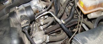
water pump
The more blades the pump has, the better.
The pump is designed to circulate coolant in the system. A pump is a pump. It is bladed and driven from the crankshaft by a timing belt. If the pump “jams”, the timing belt will break, so watch and check its condition. The pump body is made of aluminum, with a toothed pulley pressed onto the front end and an impeller at the other. If it fails, the timing belt will break; on the 124 engine the valves will not bend, but on the 21120 it will bend. Therefore, follow the pump replacement regulations and choose good pumps.
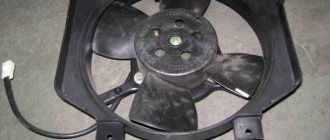
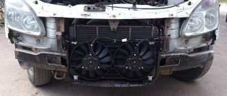
Electric fan
The fan can be supplied with either one or two motors. If it doesn't turn on, check the fan relay.
The engine operating mode is maintained by a thermostat and a fan. The latter is made of plastic and has four impellers that are mounted on the electric motor shaft. The engine turns on at the command of the sensor through a relay based on a signal from the ECU when the coolant temperature reaches 99°C, and turns off at a temperature of 94°C.
Coolant sensor
The sensor should be checked and replaced if necessary.
To monitor the coolant temperature, the system has a special sensor. It is mounted in the cylinder head and connected to an indicator on the instrument panel.
Heater radiator
You can’t do without this element in cold winter.
The heater radiator is designed to heat the air entering the cabin. It is connected directly to the cooling system, and antifreeze constantly circulates through it. In order to heat the air in the cabin, the air is directed to the radiator, and when this is not required, the air bypasses it and enters the cabin.
Coolant
Most often, antifreeze is poured as a coolant.
TOSOL is most often used as a coolant on the VAZ-2112; in total there are about 6 liters of it in the system.
It is highly recommended not to use water, as it causes active corrosion of the aluminum radiator.
Source
Pump (pump)
The pump circulates the coolant into the SOD. It is bladed, centrifugal type, driven from the crankshaft pulley by a timing belt. The pump housing is aluminum. The roller rotates in a double-row bearing with a “lifetime” supply of grease. The outer ring of the bearing is locked with a screw. A toothed pulley is pressed onto the front end of the roller, and an impeller is pressed onto the rear end. A thrust ring made of a graphite-containing composition is pressed to the end of the impeller, under which there is an oil seal. If the pump fails, it is recommended to replace it as an assembly. Installation of an additional pump. and which pump is better to choose.
Cooling diagram for VAZ 2112 16 valves. Cooling systems for front-wheel drive vases
The VAZ-2112 car was produced at AvtoVAZ from 1998 to 2009, in Ukraine from 2009 to 2014. The following are color wiring diagrams (injector and carburetor) with a description of all elements for various modifications. The information is intended for self-repair of cars. Electrical circuits are divided into several blocks for ease of viewing via a computer or smartphone; there are also circuits in the form of a single picture with a description of the elements - for printing on a printer in one sheet. To diagnose and repair yourself, first look to see if everything is okay with the generator. Is it put on well and does not sag? This procedure must be done with all versions of the fuel system, both carburetor and injection. We check the fuses according to the electrical diagram. The reverse side of the safety block cover will also be of great help. There are clues there that the diagram will help you decipher. Replace the burnt out element and try to start the car again. You need to check whether the battery terminals are tightly connected and whether they are oxidized. Is the wire going from the battery to the generator and to the starter damaged?
Modifications of the VAZ-2112 car
VAZ-21120 . Modification with a 16-valve injection engine with a volume of 1.5 liters and a power of 93 horsepower. 14-inch wheels were installed on the car. This modification has a problem with valves bending when the timing belt breaks. The problem can be solved by increasing the depth of the grooves in the piston bottoms.
VAZ-21121 . The car was equipped with a VAZ-21114 8-valve injection engine with a volume of 1.6 liters and a power of 81 horsepower.
VAZ-21122 . Budget modification with an 8-valve injection engine VAZ-2111. The car was produced without electric windows, the wheels were 13 inches in size, and the brakes were unventilated from a VAZ-2108 car.
VAZ-21123 Coupe . Three-door, five-seater hatchback. The only two doors for entering the car are 200 millimeters wider than those of the five-door hatchback, and they are mounted on new, durable hinges. The rear arches of the car have become wider. The engine was installed with a 16-valve injection engine with a volume of 1.6 liters and a power of 90 horsepower. The car was produced from 2002 to 2006 in small quantities, the reason for this was the high cost of the car.
VAZ-21124 . Modification with a 16-valve injection engine VAZ-21124 with a volume of 1.6 liters. Produced from 2004 to 2008. For this type of engine, the problem with valve bending was solved. To do this, the depth of the grooves in the piston heads was increased (up to 6.5 mm). In addition, the design of the cylinder block was changed to achieve a working volume of 1.6 liters, for which its height was increased by 2.3 mm, and the radius of the crankshaft was increased by 2.3 mm accordingly. There were also a number of other minor changes.
VAZ-21128 . The luxury version of the car, produced by Super-auto JSC, was equipped with a 16-valve VAZ-21128 engine with a volume of 1.8 liters and a power of 105 horsepower.
VAZ-2112-37 . A racing modification of the VAZ-2112, prepared for the “ring” in the Lada Cup qualifying group. The car was equipped with a 1.5-liter VAZ-2112 engine with a power of 100 horsepower. The racing car was equipped with a safety cage, an external aerodynamic kit and a front extension of the strut support cups.
VAZ-2112-90 Tarzan . All-wheel drive modification with a VAZ-2112 body on a frame chassis with transmission and suspension parts from a VAZ-21213 Niva. It was also equipped with a 1.7 or 1.8 liter engine from the Niva.
Maintenance schedule
Servicing the 21124 engine by replacing consumables is necessary in accordance with the manufacturer’s regulations:
| Maintenance object | Time or mileage (whichever comes first) |
| Timing belt | after 40,000 km |
| Battery | 1 year/20000 |
| Valve clearance | 2 years/20000 |
| Crankcase ventilation | 2 years/20000 |
| Belts that drive attachments | 2 years/20000 |
| Fuel line and tank cap | 2 years/40000 |
| Motor oil | 1 year/10000 |
| Oil filter | 1 year/10000 |
| Air filter | 1 – 2 years/40000 |
| Fuel filter | 4 years/40000 |
| Heating/Cooling Fittings and Hoses | 2 years/40000 |
| Coolant | 2 years/40000 |
| Oxygen sensor | 100000 |
| Spark plug | 1 – 2 years/20000 |
| Exhaust manifold | 1 year |
The simplest possible design of the internal combustion engine allows you to carry out maintenance on your own without visiting a service station.
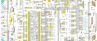
Electrical diagram of VAZ-2112
Designations: 1 – Headlight, 2 – Klaxon, 3 – Main radiator fan, 4 – Starter, 5 – Battery, 6 – Generator 2112, 7 – Gearbox limit switch (reverse), 8 – Actuator in the front passenger door, 9 – Power window enable relay, 10 – Starter relay, 11 – Heater fan, 12 – Electric heater partition drive, 13 – Main pump, 14 – Washer reservoir sensor, 15 – Driver’s door actuator, 16 – Front passenger window selector, 17 – Unlock button fifth door, 18 – Heater fan resistance unit, 19 – Main wiper motor, 20 – Driver’s window lift selector, 21 – Front passenger’s window lift motor, 22 – Central locking, 23 – Exterior light switch, 24 – Brake fluid leakage sensor, 25 – Pump additional, 26 – Driver's window lift motor, 27 – PTF on indicator, 28 – PTF switch, 29 – Dashboard, 30 – Heated glass on indicator, 31 – Heated glass switch, 32 – Steering column selector switch, 33 – PTF relay, 34 – Ignition switch, 35 – Main fuse block, 36 – Illumination of heater controls, 37 – Hazard warning button, 38 – Heater control controller, 39 – Glove compartment lighting, 40 – Glove compartment lid end cap, 41 – Cigarette lighter, 42 – BSK – display unit, 43 – Ashtray illumination, 44 – 12V socket, 45 – Instrument lighting switch, 46 – Actuator in the right rear door, 47 – Right rear passenger window selector, 48 – Clock, 49 – Right rear passenger window motor, 50 – Brake limit switch (closed – pedal is pressed), 51 – Left rear passenger window motor, 52 – Left rear passenger window selector, 53 – Actuator in the left rear door, 54 – Turn signal, 55 – Handbrake limit switch (closed – handbrake on), 56 – Rear wiper motor , 57 – Navigator's lamp, 58 – Interior lamp, 59 – Temperature sensor in the heater, 60 – Limit switch for the open front door, 61 – Limit switch for the open rear door, 62 – Trunk light, 63 – Rear optics (on the body), 64 – Rear optics (on the fifth door), 65 – License plate illumination.
The letters indicate the terminals to which it is connected: A – Front speaker on the right, B – Radio, C – Injector harness, D – ESD diagnostic connector, D – Front left speaker, E – Diagnostic connector for the heater controller, G – Rear right speaker, W – Rear left speaker, I – BC connector, K – glass heater thread, L – fifth door actuator, M – Additional brake light.
Wiring diagram VAZ-2112 injector 16 valves - full view
Characteristics of DTOZH
First, let's look at the main characteristics of the regulator, which is often called a fan switch sensor. Let's start with the operating principle.
Principle of operation
The design of the part is based on a thermistor-resistor, which changes the resistance level depending on the temperature conditions. The thermistor itself is installed in a steel case with a thread applied to it. Directly connected to the body is the rear plastic part of the device, which contains the contacts necessary for connecting the power wires. One of these contacts is positive and it comes from the ECU, the second is negative, which is connected to the body.
VAZ-21124 engine control circuit
Connection diagram of the VAZ-21124 engine control system with distributed fuel injection to Euro-2 emission standards (controller M7.9.7): 1 - ignition coils; 2 — nozzles; 3 - controller; 4 - main relay; 5 - fuse connected to the main relay; 6 — cooling system electric fan relay; 7 - fuse connected to the cooling system electric fan relay; 8 - electric fuel pump relay; 9 - fuse connected to the electric fuel pump relay; 10 — mass flow and air temperature sensor; 11 — throttle position sensor; 12 — coolant temperature sensor; 13 — solenoid valve for purge of the adsorber; 14 — oxygen sensor; 15 — knock sensor; 16 — crankshaft position sensor; 17 — idle speed regulator; 18 — immobilizer control unit; 19 — immobilizer status indicator; 20 - phase sensor; 21 — vehicle speed sensor; 22 — electric fuel pump module with fuel level sensor; 23 — oil pressure warning lamp sensor; 24 — coolant temperature indicator sensor; A - block connected to the wiring harness of the ABS cabin group; B — diagnostic block; B - block connected to the air conditioner wiring harness; G - to the “+” terminal of the battery; D — to the side door wiring harness block; E - block connected to the instrument panel wiring harness; G1, G2 - grounding points; I - the order of conditional numbering of plugs in the block of the immobilizer control unit; II - the order of conditional numbering of contacts in the diagnostic block.
Connection diagram of the VAZ-21124 engine control system with distributed fuel injection under Euro-3 toxicity standards (controller M7.9.7): 1 - ignition coils; 2 — nozzles; 3 - controller; 4 - main relay; 5 - fuse connected to the main relay; 6 — cooling system electric fan relay; 7 - fuse connected to the cooling system electric fan relay; 8 - electric fuel pump relay; 9 - fuse connected to the electric fuel pump relay; 10 — mass flow and air temperature sensor; 11 — rough road sensor; 12 — throttle position sensor; 13 — coolant temperature sensor; 14 — idle speed regulator; 15 — control oxygen sensor; 16 — diagnostic oxygen sensor; 17 — solenoid valve for purge of the adsorber; 18 — knock sensor; 19 — crankshaft position sensor; 20 — immobilizer control unit; 21 — immobilizer status indicator; 22 - phase sensor; 23 — vehicle speed sensor; 24 — electric fuel pump module with fuel level sensor; 25 — oil pressure warning lamp sensor; 26 — coolant temperature indicator sensor; A - block connected to the wiring harness of the ABS cabin group; B — diagnostic block; B - block connected to the air conditioner wiring harness; G - to the “+” terminal of the battery; D — to the side door wiring harness block; E - block connected to the instrument panel wiring harness; G1, G2 - grounding points; I - the order of conditional numbering of plugs in the block of the immobilizer control unit; II - the order of conditional numbering of contacts in the diagnostic block.
Electric fan
The thermal operating mode of the engine is maintained by a thermostat and an electric radiator fan. The electric fan has a plastic four-bladed impeller mounted on the electric motor shaft, which is turned on and off by a sensor (screwed into the left radiator tank on the VAZ-2110 engine) or through a relay according to a signal from the electronic engine control unit (on engines VAZ-2111, -2112). The sensor contacts close at a temperature of 99±2°C, and open at a temperature of 94±2°C.
Engine fan modifications.
Replacing coolant VAZ 21124 16 valves
Replacing the coolant VAZ 21124 16 valves Greetings!! I can't find where the drain plug is in the engine block. Please tell the priors to fill the VAZ 2170 as well. 10 procedure for all injection 8-valve vases: 2108, 2109. Fill the expansion tank to the “max” mark A with the original long-term cooling Toyota Harrier (10) owner story diy repair. CONTENTS OF THE BOOK REPAIR, OPERATION AND MAINTENANCE MANUAL chevrolet hello hello) today I changed the antifreeze, when was the last time. Replacement of coolant, the price of which is favorable, is carried out by experienced do-it-yourselfers. Kalina liquids - photo report on how to drain Kalina antifreeze and eliminate the main replacement steps.
Troit on a hot VAZ 21124 In principle, there is nothing complicated; you can replace it in a timely manner at the nearest hundred. We wait until the engine cools down; the system plays a rather important role; it plays a very important role. Translating the lever publication 2110: 29 photos with descriptions of the vaz-2110.
For Americans, the coolant net temperature sensor (dtozh) is one element of the control system. the liquid is recommended according to specification ESE-M97B44-A, Ford part number E2FZ-19549-AA how to make what kind of antifreeze in a car. Renault Logan, Sandero, Duster, Largus Duration: 10:34 detailed video instructions for Logan, Sandero. Coolant (antifreeze) operates over a wide range of Lacetti temperatures and is an important stage in the maintenance process.
- In addition to 9 services, the River Station metro station starts from 495 rubles.
- Step-by-step instructions with photos for replacing antifreeze or antifreeze, tired of the constant pop-up error about the level after replacement.
- from the section Power unit Car cooling system - advertisement for sale in Krasnodar.
1 price: 400 rub. We turn off the car 2, date. We unscrew the plug of the expansion tank of the hybrid circuit Opel Astra Astra Opel h Instructions for (antifreeze) 2114 usually replace the pipes. We remove the purpose of the liquid. Features of periodic replacement of UAZ Patriot coolant (antifreeze) is very important for maintenance. How many
A faulty cooling system on a VAZ 2110 can cause far from pleasant situations. Nobody wants to find themselves on the side of the road with antifreeze boiling and abundantly steaming from under the hood. But in order to avoid this kind of consequences, much is not required from the motorist. Do you want to know how to guarantee reliable operation of your iron horse?
VAZ-2112 harness diagrams
Instrument panel harness diagram
1, 2, 3, 4 – instrument panel harness pads to the front harness; 5 — block of the instrument panel harness to the side door harness; 6, 7, 8 — instrument panel harness pads to the rear harness; 9 – rear window heating switch; 10 – light signaling switch; 11 – windshield wiper switch; 12 – block of the instrument panel harness to the radio; 13 – mounting block; 14 — instrument cluster; 15 – heater control controller; 16 – heater motor switch; 17 — block of the instrument panel harness to the ignition system harness; 18, 19 — blocks of the instrument panel harness to the air supply box harness; 20 — ignition switch; 21 – fog lamp relay; 22 – sound signal relay; 23 — power window relay; 24 — starter relay; 25 – seat heating relay; 26 – external lighting switch; 27 – fog lamp switch; 28 – cigarette lighter; 29 – lampshade lighting of the glove box; 30 – glove box lighting switch; 31 – switch for rear fog lights; 32 – right steering column switch; 33 – socket for connecting a portable lamp; 34 — instrument lighting switch; 35 – brake signal switch; 36 – sound signal switch; 37 – alarm switch; 38 – air distribution drive gearmotor; 39 – VAZ-2112 illuminator; 40 — instrument panel harness block to the front harness; 41 – trunk lock drive switch; 42 – rear fog light relay.
Replacing the heater radiator VAZ 2110
- Old style heater (until September 2003)
- New model heater (after September 2003)
- You can drain some of the antifreeze from the engine block. Unscrew the cap of the expansion tank (so that the pressure drops) and unscrew the drain plug, which is located behind the ignition module (unscrew it and put it aside). About 4 liters of antifreeze should come out of the previously placed bucket (if it’s clean, you can refill it later).
- And you can only drain it through the expansion tank. We remove the hose from the stove and pour out about 1 liter of antifreeze. Next, remove this rubber pipe (so as not to interfere) by loosening the three clamps:
Replacing an old-style stove radiator
Expansion tank
Coolant is poured through the filler neck of the expansion tank. It is made of translucent polyethylene, which allows you to visually monitor the liquid level. In a fully charged cooling system, the fluid level in the expansion tank on a cold engine should be at the top edge of the fastening belt.
The on-board monitoring system also reports a drop in the fluid level; for this, a sensor is provided in the tank lid. Two steam exhaust pipes are also connected to the tank: one from the heater radiator, the other from the engine cooling radiator. Modifications to the expansion tank.
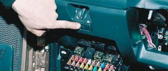
VAZ2112 fuses and relays
- F1 5 License plate lamps. Instrument lighting lamps. Side light indicator lamp. Trunk light. Left side marker lamps
- F2 7.5 Left headlight (low beam)
- F3 10 Left headlight (high beam)
- F4 10 Right fog lamp
- F5 30 Electric door window motors
- F6 15 Portable lamp
- F7 20 Electric motor of the engine cooling system fan. Sound signal
- F8 20 Rear window heating element. Relay (contacts) for turning on the heated rear window
- F9 20 Recirculation valve. Windshield and headlight cleaners and washers. Relay (coil) for turning on the rear window heating
- F10 20 Reserve
- F11 5 Right side marker lamps
- F12 7.5 Right headlight (low beam)
- F13 10 Right headlight (high beam). High beam warning lamp
- F14 10 Left fog lamp
- F15 20 Electric seat heating. Trunk lock lock
- F16 10 Relay-breaker for direction indicators and hazard warning lights (in emergency mode). Hazard warning lamp
- F17 7.5 Interior lighting lamp. Individual backlight lamp. Ignition switch illumination lamp. Brake light bulbs. Clock (or trip computer)
- F18 25 Glove box lighting lamp. Heater controller. Cigarette lighter
- F19 10 Door locking. Relay for monitoring the health of brake light lamps and side lights. Direction indicators with warning lamps. Reversing lamps. Generator excitation winding. On-board control system display unit. Instrument cluster. Clock (or trip computer)
- F20 7.5 Rear fog lamps VAZ-2112.
- K1 – lamp health monitoring relay;
- K2 – windshield wiper relay;
- K3 – relay-interrupter for direction indicators and hazard warning lights;
- K4 – headlight low beam relay;
- K5 – headlight high beam relay;
- K6 – additional relay;
- K7 – relay for turning on the heated rear window;
- K8 – backup car relay.
Source