What to do if the ignition module fails? When does it need to be changed, for what symptoms? These questions are often found on the Internet. In our article we will try to cover in detail all the nuances associated with replacing the ignition coil on a VAZ 2114. In addition, we will tell you how to check the device with a multimeter, and also consider in detail the process of replacing this part.
This video clearly shows the process of replacing the ignition module on a VAZ 2114:
How to replace the ignition module on a VAZ 2113-VAZ 2115?
Removal: 1) First disconnect the “-” terminal from the battery, thereby de-energizing it. (How to remove the minus terminal in order to de-energize the battery, see the article: “Replacing the battery”).
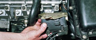
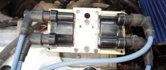
2) Then find the location of the ignition module in the engine, and after finding it, disconnect the four high-voltage wires that are connected to it.
3) Next, disconnect the wire block by squeezing the retaining clip that secures it to the module.
4) Next, remove the three nuts that secure this module to the bracket.
Note! To make it easier for you to visually determine, look at the photo below, which shows the places where three nuts secure the module to the bracket!
5) Then remove the module from the three long pins that are present on the bracket.
Installation: The ignition module is installed in the reverse order of removal, but when installing it back, you must know two things:
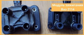
1. After the ignition module is installed, look at its surface, you see the numbers shown there: 1, 2, 3, 4. So, these numbers indicate the numbers of the corresponding cylinders.
2. Have you noticed that the same numbers are present at the tips of the high-voltage wires: 1, 2, 3, 4. All this was done to make it easier for you to determine which of the high-voltage wires should be connected to the module where.
Note! When reinstalling the module, connect all high-voltage wires strictly by numbers, for example: “the first wire - to the first terminal”, “the second wire - to the second terminal”, etc.
Checking the ignition module for functionality:
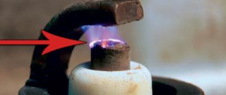
To check the module, you will need a “ high-voltage arrester ”, which can be purchased at a car store for a price in the region of 900-1500 rubles. Using this spark gap, you can check for serviceability: the ignition module, the ignition coil, and the high-voltage wires themselves for the presence of sparking.
Note! The video clearly shows that the ignition module is working properly, because when all the wires are connected to it one by one, a spark constantly appears on the spark gap, but the last check shows that the spark breaks off a little, but still the module performs well and does not need to be replaced !
Ignition switch and features of its replacement
ZZ plays an important role in the vehicle's SZ, both for an 8-cl and 16-cl engine. It is activated when the starter is working, thanks to it the lighting, turn signals, and power windows work.
Replacement or repair of the VAZ 2115 ignition switch may be required if:
- lost or broken keys;
- the lock was damaged during an attempted theft;
- the 3Z cylinder is faulty;
- The contact group does not work.
To replace you will need: a set of keys, a hammer, screwdrivers, a thin chisel.
The replacement procedure consists of the following steps:
- The car's power is turned off by disconnecting the negative terminal from the battery.
- We remove the steering wheel.
- Next you need to remove the steering column switches.
- Then you need to loosen the bolts securing the clamp that holds the ZZ on the steering column. If the heads are cut off, the bolts should be carefully knocked out using a hammer and a thin chisel.
- Now you need to disconnect the wiring harness.
- Next, you need to completely unscrew the bolts from the 3Z housing and you can remove it.
- A new device is installed in place of the old one.
- Assembly is carried out in reverse order.
After assembly, you should start the engine and check the operation of the switch (the author of the video is the MY LADA channel).
Withdrawal procedure
Release the lock and disconnect the wires from the ignition coil terminals.- Turn on the ignition and use a voltmeter to measure the voltage between terminal 15 and ground in the case of an ignition coil or between terminals C and D in the case of an ignition module on the wiring harness block. The voltage must be at least 12 volts. If there is no voltage or it is less than needed, then you need to check the charge of the battery, computer or power circuit. To check the ignition coil, you can replace it with a known good one.
- After taking measurements, turn off the ignition.
- Disconnect the high-voltage wires from the spark plugs.
- Using a 13mm wrench, unscrew the 2 bolts of the upper mounting of the coil bracket.
- Using a 17mm wrench, loosen the lower mounting bolt of the bracket and remove it together with the coil.
- Disconnect the high-voltage wires from the ignition coil
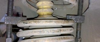
- Using a multimeter in ohmmeter mode, we measure the resistance between the central terminal 15 and the housing. The multimeter should show that there is no short circuit of the primary winding of the coil to ground. We sequentially measure the electrical resistance between the central terminal 15 and the outer terminals - 1a and 1b. The resistance of each of the primary windings of the coil should be about 0.5 ohms. When taking measurements, you need to take into account the device's own resistance.
- Using an ohmmeter, we measure the resistance between the high-voltage terminals of the coil 1 and 4, and then 2 and 3. The resistance of the windings should be about 5.4 kOhm.
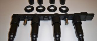
- Using a 5mm hex wrench, unscrew the 4 screws securing the coil to the bracket and remove the coil.
Winding resistance measurement
It is logical to assume that the transformer malfunction consists of an internal break or short circuit of the winding turns. In this case, the resistance at the contacts will change or the device will show a broken electrical circuit, which happens more often when the coil is broken.
This diagnostic option is suitable for all types of converters, including individual ones. The difference lies in the method of connecting the measuring device and the values of the reference resistance for elements from different brands of machines.
Before checking, it is recommended to find the characteristics of a specific coil on the Internet. Find out the resistance of the first and second windings, then proceed to diagnostics. If the technical parameters of the transformer could not be found, use the average indicators as a guide: on the primary winding the resistance should be from 3 to 5 Ohms, on the secondary winding - 10–1 kOhms.
Before starting diagnostics, disconnect the negative terminal of the battery and disconnect all wires from the converter without exception. To check the ignition coil with a multimeter, follow these instructions:
- Set the device to ohmmeter mode, the lowest measurement threshold. On most household multimeters it is 200 ohms.
- Connect the clamps to the primary winding terminals and compare the readings with the baseline characteristics.
- Using the switch, increase the measurement threshold to 20 kOhm (kilo-ohm) and similarly measure the resistance of the secondary circuit of the coil.
On older coils, the leads of the first winding are connected to two threaded rods. The second must be measured through the central contact for the armored wire and the side pin with the mass symbol.
On two-terminal transformers, the multimeter terminals are connected differently. To check the primary circuit, the measurement is made between two small terminals located on one side of the housing. The secondary circuit is connected through two large contacts into which the ends of the high-voltage conductors are inserted.
When measuring individual coils, the clamps are connected to terminals No. 1 and 3, where the ends of the primary winding come. The secondary circuit is connected to contact No. 2 and a cradle placed on the spark plug.
If during the diagnostic process of any winding the device shows an open circuit, the coil must definitely be replaced. Option two (rare): the resistance value is less or more than that specified in the characteristics. In this case, it is better to show the converter to an auto electrician - he will conduct an accurate diagnosis and announce the final verdict - install a new spare part or look for the problem elsewhere.
Functions and tasks
The module supplies high voltage to the spark plugs through the PVN. PVN are high voltage wires . Before completely changing the module, make sure that the high-voltage wires on the VAZ 2114 do not need to be replaced. Otherwise, you will waste your money.
When the module is operating, current is supplied to the spark plug. As you know, there are two of them in the car. If one is supplied with a working spark, then the second is supplied with an idle spark. The working charge is intended for cylinders 1 and 4, and the idle charge is for cylinders 2 and 3. This scheme allows the spark to be in the required cylinder during the corresponding engine stroke.
How to set the ignition yourself?
Precise ignition adjustment on the VAZ 2115 injector is performed using a special strobe light. If this is not possible, you can set the ignition on the VAZ by spark.
To do this, follow these steps:
- First of all, the engine is warmed up until it reaches operating temperature.
- The distributor does not need to be removed, but only relaxed.
- You need to remove the central wire from the distributor.
- The piston in the 1st cylinder must be at TDC (the marks are set differently on 8 and 16 valve engines).
- Now you need to hold the short-circuit wire with your left hand and turn on the ignition.
- Use your right hand to adjust the distributor counterclockwise, while keeping the high-voltage wires above the metal.
- Then similar actions are performed, turning the distributor clockwise until a spark appears.
- At this point, the alignment ends, and the distributor is fixed in its regular place.
With the ignition set correctly, the car will operate without interruption with optimal fuel consumption and maximum power.
Signs of breakdown
A malfunction of the ignition coil, or rather the module, can be determined by several characteristic signs:
- When accelerating, the car seems to fall through, there is a sharp short-term loss of power;
- The overall engine power level drops;
- Unstable behavior of the car when idling;
- The engine is shaking, which indicates cylinder failure.
Before you begin repairing the module, make sure that the spark plugs on your VAZ 2114 do not need to be replaced. Perhaps they have lost their effectiveness, the contacts have become clogged, or simply the life cycle of this component has come to an end.
Candles
High-quality spark plugs for a VAZ 2114 car with an 8-valve injection engine are not expensive, so you will not experience serious financial losses. But the ignition system and engine will work more efficiently.
But if the problem is still in the module, it is recommended to check the contacts. Most often, the basis for failure of the ignition module is the lack of quality contact. Sometimes they oxidize, stick, and the mass breaks off. Even if a layer of dust appears on the cylinder, it can fail.
The principle of operation of the ignition coil.
The module is a kind of connecting link: from the electronic control unit, which controls its working process, a certain signal is sent to the winding (in the form of charged pulses); then, the module produces high voltage, which is transmitted to the spark plugs through high voltages. This action allows the candles to produce the necessary spark to start the internal combustion of the air-fuel mixture in the chamber space.
The new generation VAZs, including the fourteenth, are equipped with an ignition system coil; it is not included in the general module, since its other important part - the switch - is located in the electronic unit. If you take the old-style VAZs, including the fourteenth with a 1.5-liter engine, then they have an ignition system module: two coils and two switches in a single housing. Two coils are connected to the cylinders by high-voltage wires (each for two cylinders: one for the 1st and 4th, the second for the 2nd and 3rd).
Signs of a faulty ignition coil:
- When accelerating you feel a failure,
- Power drops
- At idle the engine behaves unstable,
- The engine has problems (cylinders fail).
Before deciding what to do with a failed ignition coil, you need to check it. No special skill is required, just know what a multimeter is and how to hold it in your hands. Depending on the test result, you should make a decision: replace or repair.
In principle, the fundamental malfunction of the ignition coil is always the lack of normal contact. Maybe the mass has broken, maybe the contacts are stuck or oxidized. A small deposit of dust can put an entire cylinder out of working order, not to mention a modest module.
Along with possible module malfunctions, it is recommended to check all sensors - from mass air flow to DS - there is a serious possibility of failure of one of them.
Error codes
When diagnosing a car at a service station or if you have the appropriate equipment, you can determine some malfunctions of the ignition module.
There are several codes that will be very useful for you:
- If the coil of cylinders 1 and 4 breaks, the device will display error P0351;
- If there is a break on cylinders 2 and 3, the error code will be P0352;
- Code P3000-3004 indicates multiple misfires.
It would be a good idea to fully check the ignition module. The simplest diagnostics involves measuring the resistance between wiring of cylinders 1 and 4 and cylinders 2 and 3 with a multimeter. First switch the device to ohmmeter mode. If the indicator is 5.5 units, then everything is fine with your module.
Although there are three more ways to check:
- Check the wiring harness. Disconnect it and check with a voltmeter. The probe is directed to contact A, and the second to engine ground. Start the engine and check the indicators. A good indicator is about 12V. If there is no voltage, the coil may be faulty.
- Examine the condition of the high-voltage wires with an ohmmeter. If the high-voltage circuits are installed incorrectly, the module will simply burn out.
- Pull the block with the wires a little and tap on it. Contacts should not be lost in this case. If the opposite happens, this indicates bad contacts that can completely break off at the most inopportune moment in the very near future.
System diagnostics
If signs of damage are detected, there is no need to immediately remove and repair the MH. First, the spark plugs must be checked; to do this, they are removed from their sockets, and the high-voltage wires are first disconnected from the spark plugs. The spark plugs should be carefully inspected, cleaned of carbon and deposits, and then checked again.
Brown color is acceptable on these devices, but soot and carbon deposits are undesirable. If necessary, you also need to adjust the gap between the element itself and the electrodes. More detailed instructions for diagnosing the module yourself are given in the video below (the author of the video is Alexey Romanov).
How to quickly check the performance of the coil at home:
- Of course, the fastest and easiest way would be to install a unit that is known to work, but it is unlikely that anyone will carry a working spare device with them.
- While the engine is running, try tapping the coil. If you notice changes in the operation of the motor, this indicates that there is poor contact inside the device.
- The most accurate results can be obtained from diagnostics with a multimeter. You need to measure the resistance of the paired terminals of the coils, in particular the first and fourth, as well as the second and third. The parameter should be 5.4 kOhm; if the values differ, the device needs to be repaired or replaced.
Module replacement
Replacement is a fairly common solution to the problem of a faulty ignition module. The procedure is performed as follows:
- Locate the ignition module. If anything, high voltage wires go from the spark plugs to it. You can't go wrong;
- Remove the negative terminal from the battery;
- Disconnect the wiring block from the ignition module;
- Turn off the high voltage;
- Dismantle the module and remove it;
- Place a new coil, or rather a module, in place of the old device, and reassemble in the reverse order;
- Please do not confuse the location of the high voltage wires on the module, otherwise you will have to buy a new component;
- For preventive purposes, it would not be a bad idea to replace the old wires. Especially if there are yellow stripes on the tips of the spark plugs and on the wiring themselves. This is clear evidence that the elements must be replaced.
How to check input wires for serviceability
Following the recommendations of specialists, to check the condition of the wires at the input, they need to be “ringed”. What does it mean?
- Determine the operating format of the multitester in the voltmeter position, and then disconnect the wiring block from the VAZ-2114 ignition module.
- Focusing on contact A, mount the first dipstick, and fix the second one to the engine ground.
- Ask an assistant to start the car or, alternatively, crank the starter. At this time, your task is to observe the measurements on the display. Normal voltage is 12 volts.
- Carry out exactly the same actions with the remaining contact.
What to do if there is practically no voltage? Then evaluate the serviceability of the fuse - it is likely that it has blown. Find 3 safety mechanisms on the VAZ-2114 electronic control panel. So, the third 7.5 A is a device suitable for the car module.
Even if the fuse is intact and intact, there is a possibility of oxidation and wire breakage, as well as loose contacts.
What to do if there is no multitester available? A control light designed for 12 V will help solve the problem. One wiring of the lighting device is placed to the contact of the block, and the other is closed to the motor housing. After turning on the ignition, the light should flicker.
How to check the VAZ-2114 ignition module with your own hands is shown in the video instructions:
Repair
If you do not want to completely change the module, you can try to bring it back to life by repairing it. The task is not too difficult, so doing it yourself is more than possible.
- Arm yourself with 17, 13 and 10 mm socket wrenches, a screwdriver, a soldering iron, aluminum flux, nail polish, stranded wires and a 5mm hex wrench.
- The weakest point of the ignition module is the contacts.
- Start the car, pull the contacts. This will help determine if the problem really lies with poor connections.
- Stop the engine and remove the module. We told you how this is done in the previous section.
- Open the module by simply prying up the housing with a flat-head screwdriver.
- Inside there is a board with silicone film. Clean it up.
- Remove aluminum from explosive contacts.
- Now comes the most difficult stage - working with a soldering iron. The task is to solder the new wires to the place where you just removed the old ones.
- Clean the surfaces from deposits, place the board on the stove and heat it to approximately 200 degrees. You can determine the desired heating level by a slight smell.
- Start soldering. The ends of the wires are connected to the module.
- Treat the resulting new contacts with regular colorless nail polish.
- Reassemble the module in reverse order, turn on the ignition.
- If everything works well, arm yourself with sealant and glue everything as firmly as possible.
- If a transistor or switch fails, it will be impossible to repair it. These elements can only be fully replaced. But don’t worry, because their price is approximately 200-300 rubles. That is, purchasing new elements will cost a total of 500 rubles maximum.
As you can see, solving the problem with the ignition coil on the VAZ 2114 is not at all difficult. Try to remember that module and coil are synonymous. But for the “fourteenth” VAZ it is still correct to use the concept of ignition module.
But again, it all also depends on the engine used. If a specific module is used for a 1.5-liter old engine, then coils are installed on 1.5 and 1.6-liter engines of the new generation.
Connection diagram
The ignition module is part of the space under the hood, it’s easier to find it by the position of the high voltages, they go from the spark plugs straight to it.
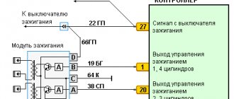
Ignition coil diagram:
VAZ 2114 ignition coil diagram
This diagram is good to follow when you have to replace the ignition coil of a VAZ 2114. In principle, everything is transparent: from contacts with the controller (ECU) to high-voltage wires. The name of the circuit is often common under the name ignition coil pinout: the pinout is a visual representation of the functionality of the device's contacts, which are numbered according to their purpose.
Basically, the most necessary knowledge about what the pinout of the ignition coil is is carried by high-voltage wires (abbreviated as HF (contacts). Because it is through the HF contacts that, in fact, the ignition module is connected to the engine system.
It can be connected in two different ways: when the ignition system coil is removed and when it is directly in its place in the car engine.
If you are holding the module in front of you:
- Let us recall the diagram: the first and fourth contacts are on one winding, the second and third – on the other (they are numbered in the diagram!)
- Then, the lower explosive contact (left) goes to the first cylinder
- On the second - upper explosive contact (left)
- The third cylinder goes to the upper explosive contact (right)
- On the fourth – lower explosive contact (right)
If the module is plugged into the engine, then pinouting the explosive contacts will be more difficult, because the device stands at an angle (as if in a diamond):
- We throw the central lower contact onto the first cylinder
- On the second - left contact
- We put the upper contact on the third cylinder
- On the fourth - right contact
Of course, the first installation option is more convenient, especially since the explosive wires require increased care in the nature of the connection (mixed up and won’t start, in the worst case, the entire engine system is ruined). Speaking to the point, it is clear that the connection diagram for the VAZ 2114 ignition module is not complicated.
By the way, buying an ignition coil is not a cheap pleasure; the price of an ignition module for a VAZ 2114 ranges from seven hundred to a thousand rubles, depending on the location of your city on the map of our country (for more information about how much an ignition module for a VAZ 2114 costs, you can find out by calling a disassembly service or a spare parts store, the running part is almost always in stock).
Operating principle and location
The ignition module is controlled by a controller, which in turn receives information about the state of the vehicle from various sensors (IAC, mass flow sensor and others). The controller also sets the sequence of operation of the ignition coils or, in other words, regulates the supply of current to the spark plugs. The ignition module operates at temperatures from −40° to +130°.
Finding its location is not difficult; high-voltage wires (HV) go from the module to the spark plugs; along them you can find the module.