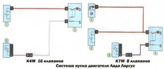
The design of the VAZ 2107 car provides for the presence of a specialized connector, the main purpose of which is to study the technical condition of the vehicle. Today, such devices are manufactured according to the same OBD2 standard. Moreover, the diagnostic connector on the VAZ 2107 of the OBD2 type has been installed since 1995, and before that, cars were equipped with OBD1 type devices. Let's take a closer look at what this device is and what its purpose is in the design of the seven.
Where is the diagnostic connector located?
The type of device in question, which is also called a diagnostic block, in the design of the 7 and other cars serves to check the condition of the vehicle for errors and malfunctions. After such manipulation, you can decide on the need to repair or replace parts and mechanisms.
Structurally, the connector is a contact connection with a large number of pins. An autonomous source (computer) is connected to this connection, and a test event is carried out using special programs. On the seven, the diagnostic connector is located in the passenger compartment on the passenger side under the glove compartment. By the way, on many car models of domestic and foreign production, the connector is also located in this place.
To connect the computer to the car via the connection, you do not need to disassemble, remove or unscrew anything. The check can be carried out while inside the car, since the essence of this process is to identify errors in the operation of the engine.
Knowing where the connecting element is located, figuring out the connection to the computer will not be difficult. To connect the computer to the car via the OBD2 connector, you will need a special cable with the appropriate plugs (connectors). However, there is an easier way to avoid buying a cable. To do this, you need to connect two contacts in the block so that the ECU displays error codes. Before connecting the contacts, you will need to understand the pinout of the block on the VAZ 2107.
Pinout of contacts of the VAZ 2107 diagnostic connector
It is known what a diagnostic block is and why it is needed in the design of the seven, so if you need to use it, you may need information about the pinout. Pinout is the designation and decoding of each contact. The design of the 7 uses 2 types of connectors - 12-pin rectangular and 16-pin trapezoidal. Determining errors can be done not only using a computer and special programs, but also with your own hands. To do this, you need to know the pinout in order to correctly connect the necessary contacts for test manipulations.
Let's look at what the pinout of each type of diagnostic pad is.
Rectangular 12-pin block
These types of devices were installed on all injection cars that were produced before 2002. Let's look at the designation of contacts:
- A is mass.
- B - engine diagnostic line.
- C - AIR.
- D - self-test lamp or potentiometer.
- H - 12V power supply.
- G - fuel pump control.
- J - socket for checking the condition of the airbags.
- M - engine and ABS check line.
Trapezoidal 16-pin block
After 2002, domestic cars began to be equipped with trapezoid-shaped pads, on which the number of contacts increased from 12 to 16. Let’s consider the purposes of the main tires:
- 2 - positive contact.
- 4 — body grounding.
- 5 - signal grounding.
- 10 - negative contact.
- 15 - diagnostic line.
- 16 - powered by 12V battery.
When you know what the diagnostic connector pinout looks like, it will not be difficult to diagnose the car yourself. Below is a diagram of the design of blocks with 12 and 16 contacts, as well as a plug, with the designation of the main contacts.
How is diagnostics carried out?
To perform diagnostics without special equipment, you will need to perform the following manipulations:
- Connect contact “B” to ground “A”.
- Turn the ignition to the engine start position, but do not start the engine.
- After this, the “Check Engine” warning light will show code 12. You can read it as follows: first, the light flashes briefly once, and after a short pause, flashes twice for 2 seconds. This code is read as "1" and "2", which results in "12".
- Code “12” means that the programs are working properly.
- After checking that the program is working properly, errors will be displayed (if any). You need to read errors using a similar checking principle.
Why does the OBD2 GM12 pin adapter for VAZ, Daewoo not work?
Having ordered an OBD2 - GM 12pin diagnostic cable and connecting it to a VAZ family car, many are faced with various troubles.
The best, so to speak, of which is simply the impossibility of diagnosing the car, but there are also cases where the fuel pump turns on or there is a short circuit in the electrical wiring, and if you’re lucky, the matter will be dealt with by simply replacing the fuses.
After such experiments, the average person takes the cable in his hands and, waving it, scolds the seller and the manufacturer.
The above troubles are usually a consequence of incorrect cable pinout, that is, power is supplied to the device along the wire through which information is to be read, or power is supplied to the fuel pump along the wire through which power is supplied. And what do you tell the latter to do? Right! Turn on and work.
But no matter how strange and incomprehensible everything now turns out to be, and it may sound absurd, the cable actually turns out to be serviceable and working. Yes, yes, workers, and even the pinout is correct. Correct, but not suitable for our car brand.
How so? You ask? And the answer here is simple. The cord is only intended for a different brand of car, and this brand is called nothing less than DAEWOO.
Where is the correct connector?
Most often it is located under the torpedo. By the way, it can be located on both the right and left sides. On certain models, the device is located near the steering column. Can be located to the left and below it. For cars that have a Europanel, the connector is located under the cigarette lighter.
Attention! The required connector can be covered with a decorative panel.
It is worth mentioning that two additional contacts, which are located on the diagnostic block of the VAZ 2114, are needed for the external air temperature sensor. After you make the connection, you will need to activate the K-line. It is necessary in order to transfer all important information to the device.
This is done as follows:
- The meter wire is connected to the second contact of the connector block.
- The second end is led to the diagnostic connector.
- The connection is made using the M-socket at the EURO 2 block, or to the seventh socket of the EURO 3 block.
- Connect the on-board computer and install it in the planned location.
Basic steps in diagnosis
When you have found the VAZ 2114 diagnostic connector, you can begin the required diagnostic work.
By the way, before installing the device, think about what exactly it will be used for. When choosing an on-board device, you need to take into account the characteristics of the car, so inexpensive models are suitable for the VAZ 2114. It will be enough to choose a system that has a monitor, a set of wires, and the processor itself.
Next, you will need to find a place where you can mount the monitor. It is necessary to take into account the individual characteristics of the machine; the optimal place is the central part of the console. When there is not enough free space on the dashboard, you should mount the monitor on the dashboard.
Remember that you need to find a place for the processor, and it is important that the ventilation holes must be freely accessible. The case should be fixed in a certain place for greater reliability.
see also
The wires deserve special attention; they must not be damaged during operation. To do this, experts advise passing them through a special tube.
After the connector for diagnosing VAZs has been found, other work has been completed, and the wiring can be connected.
After the installation is completed, you can install the software and make the necessary settings.
Now you have access to car diagnostics.
Useful video
You can get more information about connecting to the diagnostic connector from the video below:
Any VAZ-2112 car is equipped with a system for self-diagnosis of faults, which can inform the owner about the presence of any fault without visiting a service station.
Such a system works by connecting special diagnostic equipment to it and further reading and decoding errors.
When is diagnostics required?
The first sign that the car system should be diagnosed will be the blinking of the CHECK ENGINE lamp located on the instrument panel. Please note that the presence of errors in the system will be the fact that after 10 seconds after starting the engine, the warning light will not go out and the error data will be stored in the ECU memory.
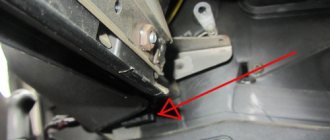
The error is indicated by an arrow.
Where is the connector?
In order to read all the fault codes that have arisen using diagnostic equipment, you will have to get to the diagnostic connector, which is located directly under the instrument panel console on the left side.
The location of the diagnostic block is indicated by an arrow.
You will detect it immediately as soon as you look at the approximate area of its location, since its characteristic shape is very specific.
How to diagnose a car
- Connect contact “B”, which has the diagnostic block and “ground”;
- Turn the ignition key to the third position, do not start the car;
- First, the “CHECK ENGINE” lamp displays code 12 with 3 flashes. It shows that the diagnostic programs are working. On the VAZ 2110 this happens in this order: the lamp blinks briefly 1 time (which should be considered the designation of number 1). After a pause lasting at least 2 seconds, it flashes 2 times in a row (two). So we got the number two. And this is repeated 3 times so that the driver understands these signs;
- After the diagnostic program has declared its serviceability, it will begin to display error codes, if there are any, of course. In the same way - flashes and pauses.
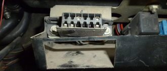
Features of the diagnostic connector
Standard 12-pin connector for diagnostics
Depending on the year of manufacture of the car, the connector can be 10-pin or 12-pin. To connect to it you will need to make an adapter.
We make wiring
You can also throw a separate wire, but this is “collective farm”.
Diagnostics of modern car models is carried out using a special diagnostic connector. It connects to a computer, which analyzes the current state of the vehicle, determines the malfunction and indicates it. If you have the appropriate equipment, you can look for breakdowns even at home. However, not all VAZ-2112 owners can find the diagnostic connector right away. Today we’ll talk about its location on the classic panel and on the Europanel. In which part of the car should I look for the required socket?
Instructions for performing diagnostics
To diagnose a VAZ, a computer or diagnostic equipment is connected using a diagnostic connector.
Computer diagnostic socket
All broadcast codes are read by the scanner. They are stored in the controller’s memory until its power is turned off. Using special software, specialists decipher the codes and determine what malfunctions and failures exist in the system.
The diagnostic procedure consists of several stages:
- Suspension diagnostics. This procedure is performed if uneven tire wear, knocking or humming is detected when driving at a constant speed, making sharp turns, or on an uneven road. And also in case of premature activation of the ABC, increased free play of the steering wheel.
- Engine check. The power engine should be diagnosed if it runs intermittently, takes a long time to heat up, is difficult to start, as well as with increased fuel consumption, loss of power, the appearance of extraneous noise, or a decrease or increase in idle speed. During diagnostics, the electrical supply and ignition system are checked, and the pressure in the cylinders is measured (the author of the video is Pavel Master).
An automatic transmission is diagnosed in the following cases:
- no gear is engaged;
- When changing gears, noises, jerking, and slipping appear;
- increased fuel consumption;
- Oil leak detected.
During diagnostics, the scanner reads error codes of the automatic transmission control system, evaluates the readings of the throttle position and cooling system temperature sensors, as well as the position of the automatic transmission selector.
First of all, diagnostics are performed using a scanner. The scanner readings are deciphered and conclusions are drawn about problems in the system. At the second stage, analog testing is carried out - wiring, contacts, and batteries are checked. Next, an online check is carried out. The screen displays indicators of sensors, fuel injection, etc. Then the data obtained during posting is analyzed. At the last stage, the error codes stored in the controller’s memory are erased. After this, reinitialization is necessary.
Where to look for the connector
It is important to know that on different cars the required socket is located in different parts of the car. Moreover, on some AvtoVAZ models it may be in a completely different place compared to another car. Let's look at several VAZ cars as an example:
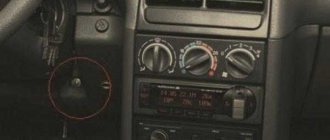
- on the VAZ-2112, as well as on the 2110, as well as 2111, the socket is located to the right of the driver’s seat, immediately under the column;
- on models 2108, 2109 and 21099, the socket you need is located under the glove compartment, on a special shelf;
- on cars with a europanel it can be found in the center of the console, near the cigarette lighter. A special decorative cover is used to disguise it;
- on Lada Kalina cars, the connector can be found near the gear shift lever. As is the case with cars with a Europanel, it is hidden under a special cover;
- on a Priora you need to look for it right behind the glove compartment, on the wall.
Thus, on the VAZ-2112 the diagnostic connector is located on the right side of the driver’s seat. It is located immediately under the steering column and, in principle, is not so difficult to find. Inspect the bottom of the panel.
Basic blocking methods
Today, blocking the diagnostic connector is one of the main options for protecting your vehicle from theft. Thanks to the blocking, the car owner will be able to prevent illegal connection to various car systems and avoid possible bypass of the anti-theft system using software. If the engine is blocked, the criminal will not be able to check the blocked motor elements.
There can be several options for blocking a device:
- The first of them is the transfer of the AR itself to another place. So an attacker who tries to steal a car will be faced with the problem of finding an AR that can be installed anywhere. The car owner can move the device to the engine compartment or hide it somewhere in the cabin.
- Re-pinning the DR contacts and making a special adapter for its use. In this case, you only need to reassign a few wires on the device. But in order to use such an DR, you will need a special adapter, where the contacts will also be re-pinned. Otherwise, diagnosing the vehicle will be impossible.
- Complete removal of the AR and installation of a non-standard device in its place. In the future, to carry out diagnostics, you will need a counterpart from such an DR with a block of wires, that is, essentially the same adapter.
- Another method that has recently become widespread is the use of the so-called secret. The secret is a device designed to enhance the functions of the installed immobilizer. As a rule, most modern manufacturers manufacture secret components in such a way that the design of the DR remains the same, and no adapters are needed for its operation. In the event of an attempted theft, the wiring that comes from the DR in the passenger compartment and in the engine compartment is blocked, and a control circuit is placed in the resulting gap. As for control, it all depends on the device manufacturer. For example, an additional DR can be installed, which will be displayed in another location, and sometimes control can be carried out via SMS commands.
Loading …
Pinout
Knowledge of pinouts may be required if a car enthusiast wants to make an adapter for computer diagnostics with his own hands, or if you need to connect without one. Experts recommend buying ready-made devices without the need to make a plug yourself. However, if you do not have such an opportunity, and diagnostics need to be carried out urgently, we will consider two main pinout options used on VAZ cars of various years of manufacture. Until 2002, AvtoVAZ products used the following pinout option:
- The 4th and 5th pins are GND outputs.
- Pin 16 – +12 V (power line).
- The 7th contact is the diagnostic line itself.
Since 2002, the pinout scheme has changed significantly. Now it looks like this:
- Pin H – +12 V (power line).
- Contact G – +12 V for the fuel pump.
- Pin A – GND output.
- Contact M – diagnostic line.
There is one important note to note regarding this diagram. If you connect the connector without a block, but directly, it is recommended to use the charge from the cigarette lighter as a source of electricity. The peculiarity of this pinout is that contact H is not always routed in the car. The use of G is also not recommended because high frequency current is supplied. This can have a negative impact on the adapter, even to the point of burning it out. However, cases of burning out the fuel pump connector are quite rare. Therefore, if you wish, you can also use this option.
As you can see, the pinout on VAZ cars of different ages is sometimes very different. Therefore, we advise you to look at the registration certificate of your car and find out what year it is made. On older vehicles you will not find the new pinout design as it did not exist yet and on newer vehicles the old design was no longer used.
Reading time
Difficulty of the material:
For fans - 3 out of 5
To diagnose a VAZ 2114, 2113 or update the ECU firmware, car owners, diagnosticians or mechanics need to know the location of the OBD2 diagnostic connector, as well as its pinout and type. To flash the electronic unit or replace it, you also need to know the location of the ECU and the purpose of the pins.
Deciphering error codes
The first character is a letter and indicates a fault block:
- B - body;
- C - suspension;
- P — engine (ECM, gearbox);
- U - data exchange bus.
The second character is a number, code type:
- 0 — SAE (standard);
- 1.2 - OEM (factory);
- 3 - reserved.
The third character is a number, system:
- 1, 2 - fuel system;
- 3 - ignition system;
- 4 — reduction of exhaust gas toxicity;
- 5 - idle;
- 6 - ECU or its circuits;
- 7, 8 — transmission (automatic transmission).
The fourth and fifth characters are numbers, the error code itself.
To diagnose a VAZ 2114, 2113 or update the ECU firmware, car owners, diagnosticians or mechanics need to know the location of the OBD2 diagnostic connector, as well as its pinout and type. To flash the electronic unit or replace it, you also need to know the location of the ECU and the purpose of the pins.
Where is the diagnostic connector for the VAZ-2114
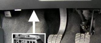
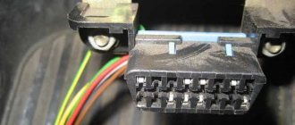
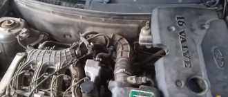
VAZ 2108-2115 with a “European panel”, the diagnostic connector is located in front of the gearbox, directly under the cigarette lighter. The block is closed with a decorative cover. On injection models since 2002, a 12-pin rectangular connector has been used.
The location of the connector is indicated on the diagram in position No. 8 . The following are visual photos of the diagnostic block.
Photo of the block location:
About the ECU and its location is written in the article “Diagnostics of VAZ 2114”. The following shows the pinout of the OBD2 connector and the assignment of contacts of the electronic control units that were installed on the Fourteenth VAZ models.
Connector type No. 1—16-pin OBD-II connector in the shape of a trapezoid:
Brands and years: some models after 2002 with control systems BOSCH MP7.0 Euro-3, BOSCH M7.9.7, January-7.2, January-7.3.
Connector type No. 2 - 12-pin rectangular connector: Make and year: all injection models, except for some models after 2002 that have an OBD-II connector
Installing a new adapter
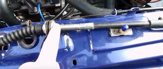
Modern adapters elm 327 with the OBD-II program (puncture) are suitable for the VAZ 2110 . You can also install them yourself. First you need to purchase an elm 327 and a cable for it. You already know the location of the diagnostic connector. Be sure to study the instructions, which indicate the pinout of the block and the location of each connector.
Connection diagram for ELM327 to 12 PIN diagnostic block
The pad can be removed quite easily. Insert your own cable into each connector of the block, making sure that the pinout of the elm 327 complies with the manufacturer’s instructions. Check that each connector is connected correctly and each cable is in the correct place. After this, the block is installed in its place.
OBD1 pinout - 12 PIN (GM12)
Description:
OBD1 (GM12) connector is rectangular in shape, consists of 12 contacts.
Brands and years:
All injection models, except for some models after 2002, which have an OBD-II connector.
Access and location:
Open access. Located next to the ignition switch, partially covered by the steering column cover.
Pinout:
| M | L | K | J | H | G |
| A | B | C | D | E | F |
| Key * | |||||
* Connector Keying - A design element of a removable connector that ensures the correct orientation of the plug and socket.
Example in the photo:
Conclusions and their purpose:
| Conclusion | Color | Purpose |
| A | Weight | |
| B | L-line diagnostics (not always routed) | |
| D | CO potentiometer (not always diluted) | |
| G | Fuel pump control | |
| H | Power supply +12V (not always wired) | |
| M | K-line diagnostics |
OBD2 pinout - 16 PIN
Description:
The OBD2 connector is trapezoidal and consists of 16 pins.
Brands and years:
Gasoline passenger cars and light commercial vehicles manufactured or imported into the United States since 1996 (US CARB and EPA legislation) and in Europe (EOBD) since 2000-2001 (European Union Directive 98/69EG) and Asia (mainly since 1998). ).
Access and location:
Pinout:
| 1 | 2 | 3 | 4 | 5 | 6 | 7 | 8 |
| 9 | 10 | 11 | 12 | 13 | 14 | 15 | 16 |
| Smaller side of trapezoid | |||||||
Example in the photo:
Conclusions and their purpose:
| № | Color | Purpose |
| 2 | J1850 Bus + | |
| 4 | Body grounding | |
| 5 | Signal Ground | |
| 6 | Line CAN-High, J-2284 | |
| 7 | K-line diagnostics (ISO 9141-2 and ISO/DIS 14230-4) | |
| 10 | J1850 Bus- | |
| 14 | Line CAN-Low, J-2284 | |
| 15 | L-line diagnostics (ISO 9141-2 and ISO/DIS 14230-4) | |
| 16 | Power supply +12V from battery |
Diagnostic connector pins for used protocols
Pins 4, 5, 7, 15, 16 - ISO 9141-2.
Pins 2, 4, 5, 10, 16 - J1850 PWM.
Pins 2, 4, 5, 16 (without 10) - J1850 VPW.
The ISO 9141-2 protocol is identified by the presence of pin 7 and the absence of pins 2 and/or 10 on the diagnostic connector.
If pin 7 is missing, the system uses the SAE J1850 VPW (Variable Pulse Width Modulation) or SAE J1850 PWM (Pulse Width Modulation) protocol.
All three data exchange protocols operate via a standard OBD-II J1962 connector cable.
The correct connection diagram for a 12 PIN block with a 16 PIN adapter
Diagnostic history with OBD II
Initially, few people cared about the convenience of automotive diagnosticians. Microcomputers that control the machine’s components could be checked using dealer tools that are not available for free sale and are not provided with open source codes. Therefore, the first step was taken by government organizations designed to monitor the environmental cleanliness of transport.
A control standard appeared in the United States, where California has always been famous as the most demanding state in limiting environmental pollution from internal combustion engines.
On the subject: What is a CAN bus in a car (device and connection diagram)
By the mid-90s, the description of the connector was finally formed in the form of OBD II, that is, the second final version. On-Board Diagnostics II became mandatory for all vehicles in the United States after 1996.
What is EOBD
The abbreviation EOBD does not add much meaning to the concept of OBD, and there is not even an exact definition of what the additional letter at the beginning means.
It could be an abbreviation for European, a hint at additional Enhanced abilities, or simply a meaningless Electronic prefix (there are simply no others).
But more often they are inclined to begin introducing a positive American standard into the production of European cars. Moreover, the US market has always been considered the most important.
As a result, in parallel with the American standards for the diagnostic interface SAE, global ISOs were also formed.
In most cases, they are identical, but with different alphanumeric designations, and more often the one that appeared earlier is used. This applies to physical and logical layer protocols.