Checking the diode bridge of the VAZ generator
| One of the reasons for a generator malfunction may be a burnt-out diode bridge (generator rectifier unit). In this case, the battery will not receive enough charge, or, on the contrary, will be overcharged. Let's look at several ways to check a diode bridge with your own hands. |
The generator rectifier diodes act as a one-way valve that allows current to flow in only one direction, thereby blocking the flow of electric current from the vehicle's on-board network to the stator windings.
| Thus, a healthy semiconductor diode conducts current in only one direction. If it does not conduct current or conducts current in both directions, then the diode is faulty. |
Diodes burn out due to moisture ingress, or from improperly lighting the car in winter (when you confuse plus with minus). Before starting work, remove the diode bridge of the generator.
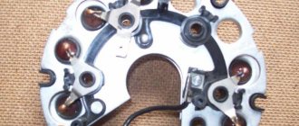
Checking the generator rectifier unit with removal and disassembly
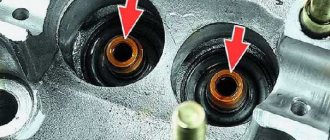
The generator diode bridge should be removed and the multimeter turned on in diode test mode. Checking the generator auxiliary diodes:
- We connect the probe of the positive terminal of the multimeter to the common bus of the auxiliary diodes (1), and the probe of the negative terminal to the terminal of the diode being tested (2). If the diode is working, then the device readings will tend to infinity;
- We swap the tester probes. If the diode is working properly, then the device readings will be several hundred ohms.
The other two additional diodes of the rectifier unit are checked in the same way; Checking the power diodes of the generator diode bridge:
- Connect the negative terminal probe of the device to the diode bridge plate into which the diode is pressed, and the positive terminal probe to the diode terminal. A working diode should not pass current, that is, the readings on the device should tend to infinity;
- We swap the tester probes. If the diode is working properly, then the ohmmeter should show a resistance of several hundred ohms.
We similarly check other power diodes of the generator rectifier unit.
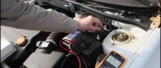
Checking the generator diode bridge without removing it
Required:
- Remove the generator protective cover.
- Disconnect terminal “B” of the regulator from terminal “30” of the generator
- Disconnect the wire from terminal “B” of the voltage regulator.
- Lamp 1..5, 12V.
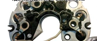
Three diodes with a red mark create a “plus” rectified voltage on the housing. They are “positive” and are pressed into one plate of the diode bridge connected to terminal “30” of the generator. The other three diodes with a black mark create a “minus” rectified voltage on the housing. They are “negative” and are pressed into another plate of the rectifier unit, connected to “ground”.
The diode bridge is checked in the order described below.
Checking positive and negative diodes for short circuits:
Connect the “plus” from the battery through the lamp to terminal “30” of the generator, and the “minus” to the generator housing. If the lamp is on, then the “negative” and “positive” diodes have a short circuit.
Checking negative diodes for short circuit:
We connect the “plus” of the battery through the lamp to one of the diode bridge mounting bolts, and the “minus” to the generator housing. If the lamp is on, it means there is a short circuit in one or more “negative” diodes (short circuit of the stator winding turns to the generator housing, or short circuit of the valves).
Checking positive diodes for short circuit:
Connect the “plus” of the battery through the lamp with clamp 30 of the generator, and the “minus” - with one of the mounting bolts of the rectifier unit. There is a short circuit of one or more positive diodes, which means the lamp will light.
Checking additional diodes for short circuit:
Connect the “plus” of the battery through the lamp to terminal “61” of the generator, and the “minus” to one of the diode bridge mounting bolts. If the lamp lights up, then there is a short circuit in one of the additional diodes. You can find a damaged diode only by removing the rectifier unit and checking each diode individually.
If a problem is found, then the generator diode bridge should be replaced. If it is working properly, then the causes of the disease may be in other elements of the generator.
| Have you ever had to check the generator diode bridge yourself? |
Photo source: Key words: xn--2111-43da1a8c.xn--p1ai
Diagnostic methods
As practice shows, diode bridges periodically fail on any vehicle, regardless of make and model
It is also not fundamentally important whether you use diode bridges from Valeo, Bosch or any other manufacturer
Most often, one or several diodes burn out in a DM. As for the reasons, here we can highlight:
- dust ingress;
- negative impact of dirt;
- contact of diodes with oil;
- accumulation of moisture in the generator;
- polarity error when lighting;
- incorrect battery connection;
- overload in the electrical network;
- errors in the installation of electrical equipment;
- factory defects, etc.
If you set a goal, the bridge can be checked in normal garage conditions. For such tasks, use a light bulb or a multimeter.
Before starting work, remove the protective casing from the DM, and also do not forget to disconnect the terminals on the regulator. Remember that all bridges are positive, that is, positive diodes are equipped with red wires, and negative ones are black. Don't get confused.
Now in more detail about each of the methods.
Multimeter
If you decide to use a multimeter to check the bridge, you will need to perform several sequential procedures.
The whole process looks like this:
- the bridge is dismantled from the generator (no other way);
- each diode will need to be checked separately;
- the beeper mode is selected on the measuring device;
- This setting will allow you to hear a signal when the probe is shorted;
- if this mode is not available, select the 1kOhm position;
- the probes are brought to the edges of the diode;
- a measurement is made;
- the probes are swapped.
Now regarding the measurement results. Everything is fine with the diode, if in one position you see an infinity sign on the screen, in the second it gives a value in the range from 500 to 700 Ohms.
If the device shows a lower resistance value, or there is an infinity sign in two positions, you have found a faulty diode.
Bulb
Now let's see how the procedure is carried out using a regular light bulb. This is a good alternative for those cases when you don’t have a multimeter.
The most ordinary 12 V lamp will do the job.
- The DM housing is connected to the negative of your battery;
- the plate must fit tightly to the car generator;
- one end of the lamp is connected to the minus of the generator;
- the second to the positive terminal 30 through the battery;
- if the lamp is on, then one or several diodes have failed;
- check negative diodes;
- the minus of the lamp goes to the body of the autogenerator;
- plus to the axle mounting bolt;
- if the lamp lights up or starts blinking, the problem is with the negative diodes;
- Next, the positive diodes are checked;
- the plus goes to terminal 30, and the minus also goes to the mounting bolt;
- when the lamp is on, we conclude that the problem is with this group of diodes;
- additional bridge diodes also need to be tested;
- the minus remains in its place, and the plus goes to terminal 61;
- if the lamp is on, the problem is diagnosed again.
To solve the identified problem, you will need to remove the problematic diode. A new one is installed in its place.
Nobody forbids you to simply buy a completely new DM and install it in place of the old one, then the question is a more substantial amount of money.
In total, checking and repairing the bridge will take no more than 2-3 hours for a technician without much experience. If you are an experienced auto mechanic, then you definitely won’t spend more than an hour of your time on such events.
Brief description, principle of operation of the generator
A car generator is an electrical machine that uses the mechanical energy of a power unit to generate electric current. Modern cars are equipped with alternating current electric generators.
The main task of the generator unit is to maintain the operating voltage of the vehicle's on-board network and charge the battery after starting the engine. Traditionally, the device is located in the front part of the engine compartment, driven by a belt drive from the crankshaft of the power unit.
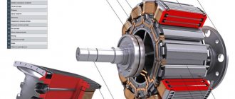
Main components of the VAZ 2112 generator
The metal case, made of two covers, is tightened with long bolts and protects the windings from mechanical stress. The material chosen is aluminum alloy, which has all the necessary qualities: lightness, sufficient strength, immunity to magnetic fields, high heat transfer.
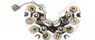
The main components of the VAZ 2112 generator: 1 – casing; 2 – output “B+” for connecting consumers; 3 – noise suppression capacitor 2.2 μF; 4 – common terminal of additional diodes (connected to the “D+” terminal of the voltage regulator); 5 – holder of positive diodes of the rectifier unit; 6 – holder of negative diodes of the rectifier unit; 7 – stator winding terminals; 8 – voltage regulator; 9 – brush holder; 10 – back cover; 11 – front cover; 12 – stator core; 13 – stator winding; 14 – spacer ring; 15 – washer; 16 – conical washer; 17 – pulley; 18 – nut; 19 – rotor shaft; 20 – front rotor shaft bearing; 21 – beak-shaped pole pieces of the rotor; 22 – rotor winding; 23 – bushing; 24 – tension screw; 25 – rear rotor bearing; 26 – bearing sleeve; 27 – slip rings; 28 – negative diode; 29 – positive diode; 30 – additional diode; 31 – pin “D” (common pin of additional diodes).
The stator is made up of tightly pressed metal plates to combat Foucault currents. The stator windings are located in thirty-six slots cut into the plates.
The rotor creates a rotating magnetic field. It consists of a core with windings of copper, varnished wires, rotates on closed, maintenance-free ball bearings. The shaft is fitted with copper rings connected to the excitation winding, a cooling fan impeller, and a V-shaped belt drive pulley.
The graphite brush assembly acts as a transmission link between the excitation winding and the battery, the self-excitation circuit.
A block of rectifier diodes, assembled according to Larionov’s circuit, converts three-phase voltage into constant power supply to the mains. A circuit of nine diodes is assembled on two metal frames used to dissipate heat during operation. Six main diodes power the on-board network. Additional semiconductor valves power the excitation winding after the generator reaches stable speeds and prevent the battery from discharging when the engine is stopped.
The voltage regulator controls the stability of the mains voltage at different engine speeds and performs temperature compensation of the battery charge depending on environmental parameters.
Algorithm for the operation of the VAZ 2112 generator
The driver turns the key in the ignition. A power circuit for the excitation winding is created from the battery. The starter rotates the crankshaft flywheel. At the same time, the generator rotor begins to rotate through the V-belt connection. The magnetic field created by the rotor current frames penetrates the stator windings. Induced electricity is generated. An alternating voltage appears at the output contacts of the device. During the time the engine is started by the starter, the generator manages to gain the required speed. The rotor winding is switched to power from a self-excitation circuit.
The rectifier module is responsible for creating direct current. The battery goes into charging mode. The voltage regulator maintains the parameters of the electrical network within specified limits.
The process of replacing the diode bridge on a VAZ 2107
Before we get started, let's select the necessary tools. Here's what we need:
- open-end wrench 17;
- open-end wrench 19;
- socket head 8;
- 10mm socket with long wrench;
- flat screwdriver;
- a new diode bridge for the VAZ 2107 (cost about 400 rubles);
- hammer.
Sequencing
When getting started, you should understand the following: before removing the diode bridge, you will first have to remove the generator and disassemble it almost completely. Without this, it will not be possible to get to the diode bridge.
- Using a 19-mm open-end wrench, unscrew the fastening nut holding the generator bracket. The generator is removed.
Video: changing the diode bridge on a VAZ 2107
One mechanic I know, who was dismantling the diode bridge of the “seven” before my eyes, several times drew attention to the following nuance: if you have already disassembled the generator, please check not only the diode bridge, but also everything else. And special attention should be paid to generator bearings
They must be checked for lubrication and play. If even a very slight play is detected, it’s time to change the bearings. Moreover, it is “bearings”, not a bearing. This is the second important nuance: under no circumstances should you leave one old bearing and one new one in a VAZ generator, because such a design will last a very, very short time. I decided to change the generator bearings - change everything. Or don't touch them at all.
ABOUT INSTALLING AN ADDITIONAL DIODE
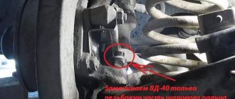
Installing an additional diode is quite rare. Why is this being done? In order to slightly increase the voltage of the on-board network. The need for this increase arose due to new laws. As you know, in 2015, changes were made to the traffic rules, forcing drivers to constantly drive with their running lights on. And owners of classic VAZ models are forced to constantly drive with their low beams on. In such a situation, both battery charging and on-board voltage drop significantly. To somehow solve this problem, craftsmen install additional diodes, which are located between the voltage regulator terminals and the common output wires for the additional diode, as shown in the figure below.
An additional diode is placed between the terminals of the voltage regulator (number 1) and the common wire for additional diodes (number 2)
For installation, KD202D diodes are usually used, which can be found in any radio parts store.
The KD202D diode is very popular among owners of “Sevens”
If the above diode is not available, you can choose any other one. The main thing is that the direct forward current is at least 5 amperes, and the maximum permissible reverse voltage is not lower than 20 volts.
So, in order to change the diode bridge on a VAZ 2107, you do not need to go to the nearest service center and pay a mechanic 800 rubles. Everything can be done on your own, and in a fairly short time. To remove and disassemble the generator, 20 minutes is enough for an experienced car enthusiast. It will take a beginner more time, but in the end he will cope with the task. All you need to do is follow the recommendations given above exactly.
How to determine the health of the generator
Information about the operating status of the main unit responsible for generating electrical energy in the car is displayed on the dashboard for the convenience of motorists. The icon on the instrument panel that resembles a battery should go out after starting the vehicle’s power unit. This means that the power to the main electrical components has been switched from the battery to the generator. If the indicator does not go out, this indicates a breakdown in the electrical circuit. Problems may also be indicated by insufficient battery charge due to the lack of normal current rating.
How to test a generator with a multimeter
The diode bridge of the generator can be checked with a multimeter, but you can also use the stand that was used to check the regulator.
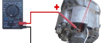
But before that, first of all, without removing the rectifier bridge from the generator, connect the red wire of the tester to terminal 30 of the generator, and the black wire to the housing. Set the tester operating mode to dial (diode icon). If it is not there, then set it to 1-2 kOhm. The multimeter should show infinity. If the readings are different, the diode bridge is faulty.
Then check the current rectifiers for breakdown. Leave the positive (red) probe on terminal 30, touch the negative one to the bridge mounting bolts one by one. The multimeter display should show infinity in all cases; any others mean a breakdown.
Next, connect the positive probe to the axle mounting bolts, and the negative probe to the generator housing. In this case, the tester should also output infinity.
But in practice, such verification is most often not enough. In most cases, it is necessary to ring the generator in more detail.
Careful testing
To do this, unscrew the fastening bolts of the rectifier unit, disconnect the copper wires of the stator winding and remove the diode bridge from the generator. Now you can test each semiconductor individually. Before checking, it is advisable to rinse the stabilizer with running water using a medium-hard brush, and then dry thoroughly. For quick drying, a hair dryer is quite suitable.
Attach one of the tester probes to the diode plate, connect the second to the central terminal of each diode fixed to this plate. Then swap the probes. In one case, the multimeter should show infinity, in the other - a nominal resistance of approximately 570-590 Ohms. Rectifiers are considered faulty if:
- In the first and second measurements (when the polarity was changed), the multimeter readings are the same;
- Diode resistance is greater or less than nominal values.
Perform the same actions with the second plate of the diode bridge. If a fault is detected in one or more diodes, it will be easier to replace the entire rectifier unit. True, there are craftsmen who replace failed diodes individually, but such work requires a certain skill and dexterity.
Checking the armature and stator windings
Further inspection requires completely disassembling the generator. First of all, visually check the anchor. Brush rings should not show any blackening, chipping or wear on the treadmills. Blackening and slight wear can be smoothed out with zero-grade emery cloth. Rings with deep grooves must be replaced or, if the thickness of the rings allows, turned on a lathe.
The armature winding should not clearly smell like burning. The color of the winding must be uniform and free of damage and breaks. To check the armature winding for a break, you will need a multimeter. Set the operating mode to continuity testing or resistance measurement and connect the probes to the brush rings. The winding resistance should be within 3-5 Ohms. Then leave one probe on the ring, connect the other to the body. The multimeter display should show infinity.
The generator stator is diagnosed after removal from the housing. First of all, carry out a visual inspection. There should be no visible damage to the wire or its insulation. Then connect the tester wire to the stator housing. With the second wire, touch the terminals one by one. There are only three of them. The tester must be in dialing mode. If the display shows infinity, this indicates that the stator is working properly.
Further testing consists of diagnosing the windings. The resistance of all three windings must be the same.
Before assembling the generator, you need to check and, if necessary, replace the bearings. When turning, they should not jam or make a creaking sound. This means that they are very worn out and will soon fail. Therefore, it is better to replace them immediately.
Checking the diode bridge using a light bulb
Naturally, not every car owner has a multimeter, and therefore you need to know how to check the vehicle’s generator using improvised means? To do this you need two pieces of electrical wire and a car lamp. The check itself involves the following simple steps:
- The protective casing of the generator is removed and a diode bridge plate is connected to the negative terminal of the battery.
- The wire from one end of the light bulb is connected to the positive of the battery, and with the other you need to touch the terminals of the remaining diodes and the connection points of the starter winding in turn.
- If the lamp lights up at any terminal of the diode, it means that this element is faulty and needs to be replaced.
In some cases, it may be necessary to check the diode bridge for an open circuit, for which you need to carry out the following manipulations:
- The wire from the negative terminal of the light bulb is connected to the negative terminal of the battery and in the same sequence as checking for breakdown of the diodes, they are tested. The only thing is that in such a situation the light should be constantly on.
- If, during the test, the light on any of the diode terminals does not light up or its light is very dim, then the part has broken and will have to be replaced.
You can find out why malfunctions occur in the diode bridge of the generator yourself in a garage. In this case, you will need a regular tester, which almost every car enthusiast has, or a car light bulb with two wires.
What malfunctions can occur in the generator?
What could be the problem with the generator when, when you turn on the ignition, the light flashes or does not turn on at all and the control devices do not function? You should check to see if the fuse located in the mounting block is ok. If there is a break in the power supply, the following may occur:
- the “O” wire with the wires from the mounting block to the devices is broken;
- there was a breakdown of the “GP” wire with the wires from the ignition switch to this unit.
If the battery is discharged, the generator voltage will not give the desired figure.
And the reason may lie in the fact that the control lamp has burned out, or perhaps the socket contacts are not pressed sufficiently against the printed circuit board. In this case, the lamp or faulty contacts are replaced.
You should look to see if there is an open circuit in the circuit connecting plug “D” of the generator and the devices. If this is exactly the case, then you need to look at the “KB” connections.
A lot also depends on the brushes if the VAZ 2110 generator does not produce the required power. They can wear out, freeze, the contact rings can oxidize, then you need to replace the entire brush holder along with the brushes. Oxidized parts are wiped with gasoline.
The terminals of the generator winding may become unsoldered from the slip rings, which need to be soldered or the surface of the generator rotor should be leveled.
A short circuit may occur in the valves, and the rectifier will have to be replaced. If the generator is noisy, it means there is a breakdown - the bearings are damaged; If the generator makes too much noise, you need to check the stator.
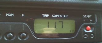
But when the generator 2110 does not produce 14.2 V, as it should, you need to start the engine - let it run for a while. In a few minutes, pressing the gas pedal, you need to increase the crankshaft speed to 3000 rpm. Now all functions should work, after which the voltage at the battery terminal is measured.
The voltage at this moment should be greater than 13 V. Other numbers indicate that there is a breakdown in the winding, or a short circuit may have occurred. You also need to check the voltage regulator with brushes; Maybe the reason lies in the oxidation of the generator winding rings.
The voltage regulator is checked by turning off all functions, but leaving the high beams on. Now you need to measure the voltage again, observing what it is now. Your mood will improve if the device shows the numbers 13.2-14.7 V.
The generator may be undercharged if the pulley is just spinning, and under heavy loads it begins to spin.
The normal output at idle is 14.2 V. Use a multimeter to take a measurement, but before that you need to check the input and output. Experienced craftsmen advise taking a welding cable, attaching the minus to the motor, and bringing the plus to the generator. If the result is negative, the generator needs to be changed.
Constant undercharging of the battery or its absolute discharge at the most inopportune moment is a headache for many car owners. One source of these problems may be the generator. But how to check it? Perhaps it's not his fault at all? Let's figure out together how much the generator must produce for the normal functioning of all car systems and maintaining the battery in a charged state.
Voltage regulator Ya112V
The generator is designed in such a way that even at low speeds it is guaranteed to develop a voltage of 13.8 -14.2 V. With a further increase in speed, the voltage can increase very strongly, which is unacceptable. As the load increases, when many devices are turned on, the voltage decreases, but it should remain at least 13.5 V.
The voltage regulator maintains the voltage within the specified limits
The voltage regulator type I 112V turns the excitation current on and off. The regulator operates in open-closed mode. With frequent switching, the rise and fall of the voltage is negligible, so the voltage remains almost constant. Voltage surges and dips are additionally smoothed out by the battery. The frequency with which the regulator operates is 20-25 Hz,
How to determine generator malfunctions
Signs of a faulty generator diode bridge. A car generator and a generator, a household power station are similar. Accordingly, the principles of troubleshooting and repair are the same. The only difference is that the car generator contains a rectifier and a voltage regulator, so the car network is designed for 12 Volts. The article discusses generator malfunctions and how you can fix them yourself. Your vehicle is equipped with a warning light that can alert you that the alternator has lost power. If this happens, you need to make sure that the sensor is working and the lamp is connected correctly.
It often happens that these lamps use a bad connector or the control relay fails. It is also possible that your battery, charging terminals are faulty, or it is simply discharged. When there is a lot of energy consumption, for example, when using lighting devices to the maximum, charging, or leaving the radio on overnight. Generator malfunctions may occur due to increased energy production when the voltage is above 14-15 Volts. The numbers vary depending on the model.
Therefore, if the battery breaks down, you should always check the generator too. Sometimes the generator begins to deliver current below the required limit of 13.2 Volts, then it is urgently necessary to check it for damage.
Before removing the generator, it is necessary to check the tension of the drive belt. Lack of electrically conductive connections between the battery or generator and the car body; voltage may be lost “on the way” to the battery. Also check the bearings for clearances and the integrity of the fuses.
For some types of faults there is no need to remove the generator. If there are knocks or noise during work, it is necessary to disconnect the wires: the noise will disappear - but a short circuit will form, unfortunately, these are expensive repairs, their cost exceeds the price of new equipment.
The noise remains - replace the bearings, they have worn out during use. Check the brushes, maybe it's time to replace them too. The contact brushes and rings may not be pressed well, then the spring should be adjusted. Get rid of dirt and burnt marks on the rings, if any. Sandpaper is the best way to remove scorch marks. If the rings become unusable, the rotor must be replaced. Check the rotor contacts with a multimeter.
Generator malfunctions in the form of a damaged rotor must be removed in the following order. Since a faulty rotor cannot be replaced, it must be completely replaced if it fails. The same applies to the stator. Remember that the rotor and stator must not have electrical contact with the body or other parts of the vehicle. A faulty stator must be replaced. Voltage rectifier diodes should not conduct current in both directions.
Recommendations
Comments 12
The fact of the matter is that the carb is new, configured with a gas analyzer, the ignition is also humming. Without a gene, there is no voltage drop directly from the battery, it’s the gene that doesn’t hold the voltage.
And the whole problem is that the pump is located exactly above the generator. Engineers are from God)))
Could it be the regulator? In contacts?
Vryatli. Moreover, during the time that I own the car, the voltage relay was changed 2 times. So they installed a three-level regulator and it only got better. It really looks like the end has come for him. There is a possibility that it was filled with antifreeze
The three-level one showed in its log what causes it to fail. In general, if the gene is flooded with antifreeze, then it should be immediately washed/changed, the bridge, brushes, and at the same time the air conditioner. Then you can clean the entire mass of the engine compartment, terminals/output genes, despite the fact that usually standard tablets larger than 13.6-13.8 are not issued in principle. By the way, the drop in speed is insignificant; this is a normal phenomenon if the generator cannot pull the load within the speed limit.
500-600 rpm is not a slight sag considering that the carbs are set at 800 rpm. But it was apparently filled with antifreeze a long time ago and it went unnoticed. When the low beam headlights are turned on, the voltage drops from 14.7 to 13.2-13.4. The car sat for 13 years, from time to time driving to the store and back. it’s not surprising if some spare parts start to break down after it’s been driven daily for six months
Well, the generator at 500-600 rpm produces approximately 5-10A, the low beam is conventionally 8-10A + engine operation, so there’s sagging, and you can also change the bearings after 13 years, they are clearly tired.
500-600 is subsidence. those. From 800 subtract 500, 300 revolutions remain. I understand subsidence of 150-200, but not 500
Rectifier block
| Control and signaling panel for the filter unit ARS-250 (400.| Boost-rectifier unit with high-voltage switchgear. |
The rectifier unit is assembled from selenium rectifiers using a single-phase bridge circuit, each arm of which consists of 39 blocks of 70 rectifier washers with a diameter of 30 mm with a permissible voltage of 20 V and a current of 300 mA. The high-voltage switchgear (RU-80), designed for a voltage of 80 kV and a load current of up to 1000 mA, is intended for connecting high-voltage circuits of an electrostatic precipitator. The device body is mounted on the cover of the boost-rectifier unit.
The rectifier unit and transformer are cooled by a fan.
The rectifier unit consists of a transformer with a 110 V primary winding and a selenium rectifier composed of several groups of selenium washers.
| Tractor valve generator. / — regulator block. 2 - stator. 3-rotor. 4-excitation winding. 5 - rectifier block. |
The rectifier unit of a tractor VG with a power of 1 kW or more is fixed on the rear cover and cooled by its own centrifugal fan mounted on the generator shaft.
The rectifier unit, just like a car VG, is fixed in the internal cavity of the generator, and the voltage regulator is on its back cover.
The rectifier block (see Fig. 2.2, block 7) is the main power source for the current circuit of the measuring circuit. It is a full-wave selenium rectifier and consists of a transformer, a selenium column, a U-shaped filter and a switch at the output of the rectifier. The primary winding of the rectifier transformer unit is supplied with a current of 220 V from the ferroresonant stabilizer SNE-05-220.
The rectifier unit includes three monoblocks connected into a full-wave three-phase rectifier circuit. Each monoblock, which is both a radiator and a conductive midpoint clamp, contains two semiconductor silicon washers.
The rectifier unit is designed to control the incandescence of emitters 13, 27 and supply the voltage to the stabilization unit.
The rectifier unit is made according to a three-phase bridge circuit. Due to the presence of a rectifier unit and the supply of constant voltage to the generator lamps, the efficiency of the installation increases.
Rectifier unit 2, mounted in the cover /, differs from traditional ones in that three additional direct conduction diodes are mounted in it (see diagram in Fig. 2.18), through which the excitation winding is powered from the generator. The rectified voltage from the additional diodes is supplied to plug terminal 10, designated pin 61 in the diagrams, and by a conductor to plug terminal / / of voltage regulator 12, which is marked V.
The rectifier unit is made according to a three-phase bridge circuit and consists of three parallel-connected selenium columns with plates measuring 100xx400 mm.
The rectifier unit consists of two rectifiers assembled in a bridge circuit on diodes 6 and 7 (D7Zh) with U-shaped inductor-capacitor filters and electronic voltage stabilizers.
The 1000 A rectifier unit consists of six valve arms. The rectifier unit is made in the form of a cabinet with double-sided doors. The cabinet contains 36 valves with coolers.
General useful information
The VAZ 2107 generator converts the mechanical energy of rotation of the engine crankshaft into electrical energy. It is also intended to power the entire on-board network, and is also necessary to recharge the battery. To convert alternating current to direct current, the unit is equipped with a rectifier unit, which consists of six diodes. A special relay-regulator serves to maintain the voltage at a given level. This device is located outside the generator.
When the ignition is turned on, the voltage, passing through the vehicle's warning lamp, reaches the regulator, and from it is transmitted to the excitation winding. It is powered by three diodes. They are located in the rectifier block. If the warning lamp continues to light during startup, this means that the battery is not sufficiently charged. You need to check the voltage status of the on-board network. If it is below normal, it means:
- a short circuit has occurred in the network;
- there are faults in the battery;
- a malfunction of the automobile relay-regulator has occurred;
- malfunction of the VAZ 2107 generator.
In this situation, you should check the belt tension, as well as the condition of its bearing, and see if the relay regulator is working. It would be a good idea to look again at the expiration date and actual condition of the battery. If everything is normal, but the voltage is not enough, you need to contact a specialist auto electrician. The generator of the presented car model does not require special care. You just need to make sure that water and dirt do not get on it. You should also check the condition of the belt (it needs to be tensioned, approximately as in the video), and it is also important that the bearing is constantly lubricated and does not create noise during operation.
A car generator is designed to generate electrical energy and power the vehicle's on-board circuit. It is driven by transmitting torque to its pulley from the engine crankshaft pulley. The generator structure consists of a stator, a rotor, a cover and a rectifier that converts alternating current into direct current.
VAZ 2107 is equipped with alternating current generators models 372.3701 or 9412.3701.