What is a diode bridge?
Diode bridge - a unit of a vehicle's electrical generator; an assembly of semiconductor rectifier diodes that provides rectification of the alternating current generated by the generator.
The electrical systems of cars, tractors and other vehicles mainly use three-phase alternating current generators. Such generators are simple in design, reliable and efficient, but they produce three-phase alternating current, which cannot power electrical appliances installed on the car. To obtain direct current from alternating current, generators use a diode bridge or a rectifier module.
The diode bridge is connected to the stator windings of the generator and ensures the conversion of three-phase alternating current to direct current. From the output of the diode bridge, current flows to the battery and to all consumers present in the automotive electrical system. A malfunction of this module often makes the vehicle impossible to operate. In order to properly carry out repairs, it is necessary to understand the types, designs and features of diode bridges of modern generators.
Diode bridge of the VAZ 2114 generator: check, replacement and repair
The diode bridge (rectifier) is one of the key components of the VAZ 2114 generator. The failure of this unit makes it impossible for the generator to function normally, and also threatens the risk of breakdown of all electronic systems of the car, so owners of the fourteenth should regularly check its condition.
Generator diode bridge
From this article you will learn why a diode bridge is needed, what design features it has, possible causes of bridge problems and methods for identifying them. Studying theoretical material will give you the opportunity to replace the unit at home, without having to spend money on the services of specialists at a service station.
Functional purpose and features of the rectifier
The diode bridge of the generator, depending on the type, can consist of either 4 or 6 diodes that perform the function of converting alternating current into direct current with a given pulsation frequency. The operating principle of the device is based on the bipolar rectification method, which is also widely used in a variety of electronic systems.
In addition to the conversion, the unit acts as a valve, the purpose of which is to pass current exclusively in one direction. With a properly functioning device, the current from the generator enters the fourteenth power network, but does not pass back to the stator. If the node fails, current leaks and flows in both directions. This will cause a constant lack of power, and the vehicle's systems that consume electricity will not be able to operate.
The VAZ 2114 is equipped with a three-phase rectifier, which has the following advantages:
- Converts alternating current into direct current with the lowest pulsation frequency: the lower the frequency, the more stable the vehicle’s electronic systems will function;
- Can be equipped with diodes of both bridge and half-bridge types;
- Makes it possible to install a current filter - a capacitor.
The cost of a diode bridge ranges from 500 to 1100 rubles, depending on the manufacturer. The market offers rectifiers both from Chinese companies, which have a low cost and questionable quality, and from well-known brands, the reliability of their products has been tested by many car owners.
As evidenced by reviews from the owners of the fourteenth, devices from LG have proven themselves to be the best. The best option in terms of price-quality ratio is the LG 0108 model. It can also be used as a diode bridge for a VAZ 2115 generator.
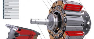
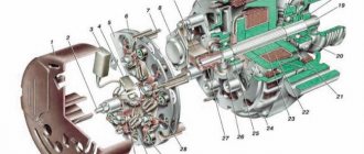
Components of the generator, number 9 – rectifier
Checking the diode bridge
A typical failure of the unit is the failure of the diodes due to burnout. The following reasons for this malfunction can be identified:
- Moisture, oil, dirt or dust getting on the diodes;
- Working out the operational resource.
There are several ways to inspect the generator diode bridge on a VAZ 2114, and the simplest of them is checking with a light bulb and does not require dismantling the device, but in order to repair the diode bridge or replace it, the rectifier will have to be removed.
Method No. 1: checking with a control (12 V light bulb)
- We connect the rectifier plate to the battery (terminal “-”) so that it fits tightly to the ground of both devices.
- Using a 12-volt light bulb, we connect one of its wires to the “+” terminal on the battery, and the second to the terminal of additional diodes. Next, we transfer the wiring from the “+” terminal to the bolt, which is located in the area of the rectifier stator winding.
Neither in the first nor in the second case should the contacts be closed - if the control lights up or blinks, it means the unit is faulty.
Method No. 2: examining the rectifier for broken contacts
- We connect the negative wire of the control lamp to the “+” terminal of the battery;
- We connect the plus control to the “-” terminal of the battery.
- Now we check the same places as indicated in the second paragraph of the previous algorithm.
Here, on the contrary, the light should be on. The absence of light or periodic blinking indicates a break in the rectifier stator winding.
Method number 3: checking the rectifier using a multimeter
Testing the device with a multimeter involves removing the rectifier from the generator housing. You can find out how this is done in the next section of the article.
What you need to know about diode bridges
First, we will look at what they are and what is inside a diode bridge. These circuit elements are available in two versions:
- From discrete (separate) diodes. Usually soldered on the board and connected by tracks in the correct circuit.
- Diode assemblies. The assemblies can be either single-phase bridges for rectifying both half-cycles of alternating voltage, or assemblies of two diodes connected in a circuit by a common cathode or anode, and other connection options.
In any case, the rectifier single-phase diode bridge consists of four semiconductor diodes connected to each other in a series-parallel manner. Alternating voltage is supplied to two points at which the anode and cathode are connected (opposite poles of the diodes). Constant voltage is removed from the connection points of like poles: plus from the cathodes, minus from the anodes.
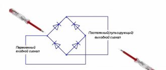
In the diagram, the connection point for alternating voltage is indicated by the symbols AC or “~”, and the outputs with constant voltage are “+” and “-“. Draw this diagram for yourself, it will be useful to us when checking.
If you imagine a real diode bridge and combine it with this circuit, you get something like:
This is interesting: Which HB4 lamps are better to put in a car - let’s get to know the question
Device
A diode bridge is an electrical device that is designed to convert or rectify alternating current and create it pulsating or constant. Such rectification is called full-wave rectification. There is also another concept in the reference book. A diode bridge is considered to be a bridge circuit of diode connections to rectify alternating current and make direct current out of it. This is the simplest and most common rectifier used in radio engineering, electronics, automobiles and other areas where it is necessary to obtain pulsating and constant voltage.
Definition
The second name for a diode bridge is a full-wave rectifier. It includes semiconductor rectifier diodes or Schottkin electrodiodes. The elements can be separately soldered on the board. The modern version combines diodes in one housing. This is called a diode assembly.
Diode bridge device
The use of diode bridges is extensive. They can be seen in electronics, transformer and switching power supplies and fluorescent lamps. Semiconductor diode assemblies are installed in the welding machine and are attached to heat-sinking devices.
A diode bridge is usually installed at the input of the power circuit when rectifying the mains voltage. A similar solution can be used in a switching power supply, including a computer power supply. It can also be used in the secondary transformer winding of a power supply, old TV or low-power home radio.
Modern power supplies are equipped with pulse circuits, where the diode bridge is responsible for rectifying the mains voltage, and the transformer is responsible for controlling semiconductor switches or transistors.
Note! Failures in the diode bridge can be due to rapid discharge of the battery, lack of recharging from the generator device, overcharging of the battery and boiling of the electrolyte.
Rapid battery discharge as a cause of electrode failure
What does a diode bridge look like?
Finding the rectifier on the board is not difficult, but the appearance varies depending on the device. Often four diodes are soldered side by side and assembled in one housing - this is a rectifier assembly. The photo shows several options:
In such options there are four pins: two are designated as “+” and “-” (outputs), and two without symbols or are indicated as “~” or “AC” (inputs).
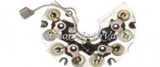
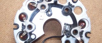
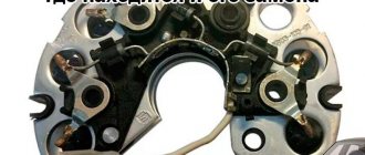
The diode bridge of a car generator looks different: it is a pair of metal conductive plates on which diodes are located in a certain sequence.
The bridge can have not only power diodes, but also auxiliary diodes:
Here the power diodes are marked in green. It’s better to test everything, especially since it’s not difficult to do.
DM functions
If we recall the physics course from school, we will conclude that there are two types of electric current. It is constant and variable. How are they different from each other?
There's nothing complicated here. The key difference is that alternating current has charged particles that move in different directions. In the case of direct current, movement always occurs in only one direction.
I would like to note that alternating current has noticeably better economic characteristics. They cope more effectively with transmitting current over fairly long distances. The only problem is that most electrical appliances in vehicles are powered by direct current. In order for a vehicle to function properly, electrically dependent equipment must receive a certain amount of direct current. The generator itself cannot provide it, since it produces alternating current.
Our today's hero allows us to solve this problem. That is, a diode bridge. It looks like a pair of metal conductive plates. They contain diodes that act as semiconductors. They are installed in a certain sequence.
The DM allows current to pass, but the bridge sets one direction. That is, the straightening process occurs. Another nuance is that the bridge sets traffic in only one direction. Namely, from the generator to the on-board network.
The serviceability of the DM is not eternal. Periodically, the generator element fails
And it doesn't matter what kind of car you have. It could be:
- VAZ 2107;
- VAZ 2114;
- Toyota Corolla;
- Lada Priora;
- Nissan Qashqai;
- Daewoo Matiz;
- VAZ 2110;
- Mitsubishi Lancer;
- Ford Mondeo;
- UAZ Patriot;
- Hyundai Solaris, etc.
Regardless of the car, you can and should check the functionality of the device with your own hands. For these purposes, it is important to use a tester.
If you are not sure about the correctness of your actions, watch visual videos. Don’t rush to blame the bridge for everything. Without disassembling or unsoldering the diodes, first make sure that it is faulty.
Principle of operation
The operation of a diode semiconductor bridge that conducts current is simple. The principle of operation is based on the property that a semiconductor diode passes electric current in one direction and does not pass in the other. So, if the charges are connected correctly, current will flow through the device.
The difference between alternating current and direct current is that it can only move in one direction. Moreover, do this in one half-cycle. During the other half of the period, it can make the opposite movement. When several diodes are connected in a circuit, they will begin to move, creating a direct current.
It is easy to assemble a diode bridge circuit. Anyone can do this. It includes four diodes, which are connected to each other by a square. Current is supplied to several opposite corners from the generator apparatus. From several other opposite angles the constant is removed. During the first period, several electrodiodes are opened and the alternating voltage wave is rectified. In the second period, several more diodes are opened. Thus, the second wave is transformed. The result is a constant voltage with a pulse frequency several times higher than that with alternating voltage.
Interesting! The presented scheme has its pros and cons. To use rectified current, the pulse component must be smoothed with a filter. Thanks to rectification, it is possible to power the transformer and reduce its volume. Among the disadvantages, note the fact that power is lost due to thermal dissipation, the voltage drops twice and the device breaks down if one diode fails.
How the device works
How to check without dismantling
You can diagnose the device on site without disassembling the generator or desoldering the part. To do this, unscrew all the wires on the generator and voltage regulator, set the tester to ohmmeter mode, and connect the lamp to the battery in the manner described above.
This method allows you to check the serviceability of the entire bridge and individual groups.
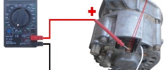
Short circuit
For this test, the positive electrode is applied to output 30 of the generator (“plus” of the power rectifier), and the negative electrode is applied to the housing. A resistance value of 1 indicates that the bridge is in good condition.
One end of the lamp is connected to the negative terminal of the generator, the other to the positive terminal. A lit lamp indicates a short circuit.
Negative group
The negative electrode of the tester is connected to the frame of the generator, the positive electrode is connected to one of the diode bridge mounting bolts. The negative group is operational if the resistance is infinity.
To check with a lamp, connect its minus to the generator casing, and the plus to the axle mounting bolt. The lamp lights up or flashes when there is a malfunction in the negative group of elements.
Positive
The positive probe of the multimeter is connected to the positive terminal, the negative one to the bridge mounting bolt. With a working group, the resistance is infinite.
The negative of the lamp is connected to the bridge mounting bolt, the plus is applied to the positive terminal. A lit lamp indicates a short circuit in the positive semiconductors.
Minor group
The positive electrode of the tester is pressed to terminal 61 (usually the “plus” of the additional rectifier), the negative electrode is connected to any bridge mounting bolt. The diodes are serviceable with a resistance value of 1.
The negative end of the lamp is connected to the bridge mounting bolt, and the positive end is connected to terminal 61. A lit lamp indicates a malfunction in this group.
Bridges can be made of individual diodes or made as a monolithic structure (diode assembly)
Methods for diagnosing performance
To independently detect faults in the rectifier unit, you will need a multimeter (tester) or a 1–5 W, 12V lamp. The bridge is removed from the generator. It is recommended to diagnose each diode one by one.
Multimeter (tester)
Measuring DC and AC current with a multimeter will help diagnose diode failure
The tester is set in ohmmeter (1 kOm) or diode monitoring mode. One electrode is tightly fixed to the frame of the diode or the plate on which it is fixed, the second to its terminal. Then the electrodes are swapped. For a working diode, one indicator will be equal to 400–800 Ohms, depending on its power, the second will be equal to 1 (tends to infinity), which indicates a closed (locked) direction. The remaining diodes are checked in the same way.
The operating resistance on all semiconductors should not differ significantly. The permissible difference in resistance of semiconductors on one wafer is 5 units. A diode with an exceeding deviation does not work well, which will lead to charging problems.
Units on both sides indicate diode damage. When the tester produces any values when changing electrodes, the diode has a short circuit.
It is acceptable to set the multimeter to test mode, but this method is less accurate. In this case, with a correctly functioning diode in one position of the probes, the tester will emit a sound signal, and in another it will be silent. A squeak or silence on both sides when changing electrodes indicates damage to the diode.
Video verification instructions
More information about diagnostics on a VAZ (video with diagrams from a practitioner)
A light bulb
In the absence of a tester, the operating condition of the semiconductors is checked with a test lamp. Why connect the battery to the lamp and form a gap near it, the stripped ends of which will serve as probes to facilitate testing. The probes are simultaneously pressed against the body and the diode terminal, then the polarity is changed. In one position, the lamp will light for a working semiconductor, but not in another.
Circuit for checking a diode bridge using a light bulb
Multimeter testing method
The most informative is a full check of the diode bridge. To implement it, you will need a multimeter, tester or Tseshka - any of these devices is equally suitable for measurements.
Determine the purpose of the pins.
The method is universal, so you can check both the diode rectifier as an assembly and the design of individual parts without disassembling them.
Install the multimeter probes.
Install the multimeter probes into the appropriate connectors on the device, observing the color markings (black - minus, red - plus). Switch the switch to dialing mode.
Use the negative lead of your multimeter.
Connect the negative probe of the multimeter to the plus of the diode bridge, and the positive one in turn to each of the AC voltage terminals.
As a result of touching, the opening voltage of the diodes should be displayed on the multimeter display; at both points this measurable value is the same for each measurement. Otherwise, the assembly is faulty.
Swap the tester probes.
Next, you need to swap the tester probes - set the red one to positive, and alternately touch the black leads to the AC voltage terminals.
The display will display a unit, indicating an infinitely high resistance - with reverse polarity, the diodes remain closed. Otherwise, if any voltage is displayed, the bridge is broken.
Use the positive lead of your multimeter.
Touch the positive probe of the multimeter to the negative terminal of the diode bridge, and touch the negative terminal in turn to the variable terminals. In both cases, the voltage drop should be displayed on the display.
Use the black probe.
Install the black probe on the negative terminal of the assembly, and connect the red probe to the variable terminals. There must be a unit in both positions on the multimeter, otherwise the element is broken.
How is the replacement performed?
Let's say checking the diode bridge shows that there is a problem. It is necessary to disconnect all wires from the generator, remove and disassemble the device. In some models, the part is attached directly to the unit with bolts, but there are devices in which the housing must be removed to access the rectifier.
Next, as part of the repair, faulty diodes are replaced - if this is economically feasible and it is difficult to find the required generator model on sale. Or they change the component entirely. Upon completion of work on the stand, the serviceability of the component and the electrical system as a whole is checked using a multimeter, and the part is assembled and installed on the car.
You can check the diode bridge yourself if you have the time and skills to disassemble the generator. But even after checking and detecting faulty diodes, you will need to select and correctly install a new element instead of the faulty one. Remember that a faulty generator can cause failure of expensive electrical equipment, short circuits and spontaneous combustion of the car. Therefore, it is better to trust repairs and diagnostics to car service technicians, who will definitely be able to call you correctly!
Testing the diode bridge with a multimeter
Any part on the board can be desoldered for testing or ringing without desoldering. However, the accuracy of the check in this case is reduced, because perhaps a lack of contact with the board tracks, with visible “normal” soldering, the influence of other circuit elements. This also applies to the diode bridge; you don’t have to desolder it, but it’s better and more convenient to desolder it for testing. A bridge assembled from individual diodes is quite convenient to check on the board.
Almost every modern multimeter has a diode test mode, usually it is combined with an audio continuity test of the circuit.
This mode displays the voltage drop in millivolts between the probes. If the red probe is connected to the anode of the diode and the black probe to the cathode, this connection is called forward or conductive. In this case, the voltage drop across the PN junction of the silicon diode is in the range of 500-750 mV, which you can see in the picture. By the way, it shows a test in resistance measurement mode, this is also possible, but there is also a special diode test mode, the results will be, in principle, similar.
If you swap the probes - red to the cathode, and black to the anode, the screen will show either one or a value of more than 1000 (about 1500). Such measurements indicate that the diode is working; if the measurements differ in one of the directions, then the diode is faulty. For example, if the continuity test is triggered - the diode is broken, there are high values in both directions (as with reverse switching on) - the diode is broken.
Important! Schottky diodes have a lower voltage drop, about 300 mV.
There is also an express check of the diode bridge with a multimeter. The procedure is as follows:
- We place probes at the input of the diode bridge (~ or AC), if the continuity test works, it is broken.
- We put the red probe on “–”, and the red one on “+” - a value of about 1000 appears on the screen, swap the probes - on the screen 1 or 0L, or another high value - the diode bridge is working. The logic of this test is that the diodes are connected in series in two branches, pay attention to the diagram, and they conduct current. If the positive power supply is applied to – (anode connection point), and the power supply minus is applied to “+” (cathode connection point), this is what happens during dialing. If one of the diodes is broken, current may flow through the other branch and you may make erroneous measurements. But if one of the diodes is broken, the voltage drop across one diode will be displayed on the screen.
The video below clearly shows how to check a diode bridge with a multimeter:
How to properly check diodes with a multimeter
A diode is the simplest semiconductor, the structure of which contains a PN junction and 2 electrodes: a cathode and an anode.
A feature of this element is the current flow capacity in only one direction: from the anode to the cathode. In this case, “+” is applied to the first electrode, and “-” to the second.
If connected incorrectly or exposed to electrostatic discharge, the diode may fail. To check a semiconductor for serviceability, you should determine its type and stock up on a multimeter tester.
Method for checking a diode bridge
Since diode bridges in one housing are increasingly used in electronics, the question arises about the methodology for testing them. I am often asked the question: “How to check a diode bridge?”
I have already talked about testing conventional diodes, but somehow I lost sight of the topic of testing diode assemblies. Let's fill this gap.
To begin with, let us recall the basic properties of the diode and the diode bridge circuit (the so-called Graetz circuit).
As you know, a diode passes current only in one direction - this is its main property. The diagram of a diode bridge according to the Graetz circuit is shown in the figure.
An alternating voltage is supplied to the terminals with the “~” sign; the polarity of the connection is not important here. Simply put, the two “~” pins are an AC voltage input.
The constant voltage is removed from the “+” and “-” terminals. In fact, it is pulsating, but that’s not about that now.
Sometimes the terminals for connecting alternating voltage (~) are also marked AC, which means Alternating Current - translated from English as “alternating current”.
So, we’ve refreshed our memory, now let’s think about how we can check the diode bridge with a multimeter.
For experiments, let's take an RS407 diode assembly with a forward current of 4 amperes and a reverse voltage of 1000 volts. We also need any digital multimeter.
Turn on the multimeter in diode test mode. Usually it is combined with the “dialing” mode and is indicated on the instrument panel with a diode symbol.
To make it more clear, let’s draw a diagram of a diode bridge on paper and follow the drawing as a guide. Next, let’s check the diodes, which are indicated in the figure as numbers 1 and 2. To do this, connect the positive probe of the multimeter (red) to the negative terminal of the diode bridge. And we connect the negative probe (black) to the bridge terminals with the “~” sign or the abbreviation AC. Since there are two diodes, we perform this operation one by one.
Since in this case the diodes will be turned on in the forward (conducting) direction, we will see numbers like 0.562V (562 mV) on the multimeter display. This is the voltage drop across the PN junction of an open diode. It is also called threshold, i.e. To open the diode, you need to exceed this voltage. In foreign datasheets, this parameter is called Forward Voltage or Forward Voltage Drop (abbreviated as Vf), which loosely translated means “voltage drop in direct connection.”
For silicon diodes, the threshold voltage (Vf) is 400...1000 mV.
Now we connect the black probe to the other terminal of the bridge with the “~” symbol or the abbreviation AC. The result should be similar. Take a look.
As you can see, this diode also conducts current in direct connection, and the threshold voltage is slightly different (566 mV), this is normal.
To 100% make sure that diodes 1 and 2 are in good condition, let’s check them when they are turned back on. To do this, connect the negative, black probe of the multimeter to the negative terminal of the bridge (“—”), and connect the red positive probe in turn to the terminals marked with the “~” symbol.
Checking one diode...
...second.
In both cases, the display will show one, indicating a high resistance of the PN junction. When connected this way, the diodes do not allow current to pass through. They are fine.
So, we checked diodes number 1 and 2 and made sure that they pass current in one direction.
Now we check the other part of the bridge - diodes 3 and 4. To do this, connect the negative probe of the multimeter to the positive terminal of the bridge and, in turn, connect the red probe of the multimeter to the AC terminals of the diode assembly. This will be a test of diodes when connected directly.
As you can see, diodes 3 and 4 are working. To be more confident, we change the probes and check them when they are turned back on, in the same way as we did with diodes 1 and 2. In both cases, the display should show one.
To many, this verification technique may seem complicated and tedious. Yes, I would call this testing “meticulous”, but it is very effective since we check all the diodes of the assembly individually.
How to detect a diode bridge on a board
Before you start checking or ringing the diode bridge, you should first find it on part of the board. To do this, you need to understand how it looks. The appearance depends on the type of case. Rectifiers can be four separate semiconductors, which are soldered side by side, or diodes, which are collected in one part of the housing. The second ones are called rectifier assembly. Here are just a few types of such assemblies.
Despite the fact that the diode bridge comes in different forms, understanding what exactly it is is not as difficult as it might seem. It comes only with four terminals and several of its rectifier terminals are marked with plus and minus. They are supplied with voltage, which means alternating current or AC in English. There may be no symbols at all. The bridge is located near the power supply wires. As a rule, it can be found at a transformer or switching power supply plugged into the power cord.
Diode bridge on board
How to check a diode bridge with a multimeter in a circuit
Let's look at how to check a diode bridge with a multimeter without removing it from the board. First of all, you need to supply power to the circuit. And by the ratio of the input and output voltages, you can determine the nature of the malfunction of this electronic device. If it is working properly, then the rectified voltage will be slightly higher than the input alternating voltage.
There are fundamentally two types of diode bridge malfunction: break and breakdown of one or more diodes of the rectifier bridge.
In the event of a break, for example VD1, the current in one half-cycle corresponding to the operation of the pair VD1 and VD3 will not flow, since a break in the electrical circuit is formed. This will lead to a sharp decrease in the rectified voltage Ud. However, if the circuit operates without a load, then this type of malfunction may not be noticed, since a capacitor is most often installed after the rectifier and, in the absence of a load, it is charged to the amplitude value of the rectified voltage. Therefore, you should be careful in this case.
In the event of a breakdown and short circuit, for example the same VD1, in one half-cycle the secondary winding of the transformer will be short-circuited. As a result of this, intense heating of VD3 will occur, which will lead to increased heating of the entire diode bridge. The secondary winding and the transformer itself will also heat up. It is difficult to judge the nature of the malfunction based on the voltage difference here. Since when the winding is short-circuited, the voltage on it during the corresponding half-cycle is also almost zero. Therefore, at the output of the diode bridge in the same half-cycle it will be almost zero, and accordingly its average rectified value will decrease.
Also, with this malfunction, the fuse installed in the primary winding of the transformer may trip, since the current in the transformer circuit will increase. I hope it is now clear how to check the diode bridge with a multimeter.
How to check a car generator? 5 ways to test with a multimeter
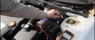
This method is one way to test your alternator without a car. Diagnostics requires access to the battery and the device itself.
For what reason can a generator fail?
The voltmeter is used in measurement mode and is connected to the common ground and the B+ terminal of the battery. When a special device is turned on in its window, the indicator should not exceed 0.5 mA.
If this value is higher, it means the diodes are faulty or the integrity of the winding insulation is damaged. This check must only be carried out with the motor connected. This method is quite problematic and requires a lot of time and accuracy. The essence of diagnostics is to measure the current strength of devices that consume electricity. The engine must be running and the speed must be as high as possible
The probe is connected to the wire going to terminal 30 or B+. Turn on all electrical devices in the car one by one and pay attention to the multimeter readings. After receiving the results, add the numbers. Then turn on all electrical appliances and compare the readings of the measuring instruments with the sum of the previous tests.
It is normal if the index is 5 A less than the amount received, but an increased value indicates a faulty part.
Check Features
The engine must be running at maximum speed. The multimeter is connected to pin 67. The device will immediately show the result and the value of the excitation current. During normal operation of the generator, this value is in the range of 3-7 A.
- The condition of the winding can be checked not only visually, but also using special instruments. The manipulation consists of carrying out preparatory work:
- dismantling the brush holder;
- dismantling the voltage regulator;
- removing slip rings;
Make sure the winding is not damaged.
After completing the preparatory work, you will need an ohmmeter. The device spindles are attached to the slip rings and stator, and then tested. Normal values are between 5 and 10 ohms.
The generator is diagnosed in a disassembled state with an ohmmeter. The device is connected to terminal 30 and the generator housing. The part must always be clean, since even a small amount of dirt can lead to a change in the data obtained.
Using an ohmmeter, all components and parts are checked one by one, so that at the end of the diagnosis, you can make a list of damaged parts. It is quite possible to eliminate detected faults on your own. You will need a minimum set of tools, as well as a full set of spare parts.
How to check without installation
You can check household or automotive equipment on site without having to disassemble the generator and solder off the parts. This is not a difficult task. To do this, you need to unscrew the existing generator wires with a voltage regulator, which play a big role in the process, set the control multimeter tester to ohmmeter mode and connect the lamp to the transport electrical equipment.
Test diagram without installation
Thanks to this method, you can quickly check the serviceability of the entire bridge or individual diodes without looking at the table of contents of textbooks. Semiconductors can also be tested using a lamp. To do this, the battery is connected to the lamp and a break is made near it. The stripped ends will serve as feeler gauges to make checking easier. Together they attach to the body part and diode terminals in one polarity, and then in the other. In the first case, a working semiconductor will light the light bulb, but in the other case this will not happen. In this case, a quiet squeaking sound will be heard, and a current conversion will occur.
Ideas for improving the generator and their implementation
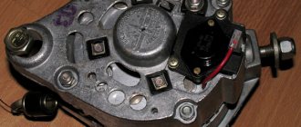
One option for modifying the unit is to install a three-level voltage regulator.
How to complete this task:
- Disconnect the terminal from the battery. You need to unscrew the M6 nut on the unit, to do this you will have to use the S10 key, and also move the wires to the side.
- Then the “female” block will need to be pulled off, after which, by prying up the three latches, it is necessary to dismantle the plastic casing of the device.
- Unscrew the two bolts that secure the assembly itself, dismantle the connector and remove it. At the same stage, you will need to unscrew another M6 nut and slightly modify the ends of the spacer sleeve using a file. This will ensure better contact of the device with the diode bridge.
- After this, install the brush holder in place of the adjusting mechanism. To do this, you need to slightly seal the hole through which the wiring enters; use sealant for this.
- Once the plastic casing is finished, it can be put back in place.
- Route the new cable along the existing wiring to the location where the new regulator will be located. Secure it with clamps. In order for the contact of the three-level regulator with the ground, that is, the car body, to be of the highest quality, you can make a shunt by connecting the body of the unit with the new regulator.
- Now all you have to do is screw the remaining wires into place and start the engine to check the operation of the regulator with the voltage consumers turned on. When checking, it is necessary to activate all equipment - radio, optics, heater, glass heating, etc. (video author - Pavel Dorokhov).
Safety precautions
It is important to understand that almost all modern equipment has a switching high-voltage power supply. This means that the diode bridge in each device is under a three-hundred-volt voltage, as well as the AVBbShv power cable. For this reason, before taking measurements, it is necessary to turn off the device from the network and discharge the smoothing electrolytic capacitor, which contains a dangerous charge. To make this more clear, dangerous elements are marked in the figure with red arrows.
Dangerous equipment items
To discharge them, it is necessary to short-circuit the capacitor terminals using a screwdriver. It is important to hold the insulating handle while doing this. It is equally important not to rush to connect the power plug after making repairs. First, you need to connect the device to the network through an incandescent light bulb with a power of 200 watts. If properly repaired, the light bulb will produce a weak light. If the repair is unsuccessful, it will be bright and indicate that a short circuit may occur.
Note! When making all kinds of network switching, you need to protect your eyes. If the switching power supply is not properly repaired, its cells may explode, releasing acidic electrolytes.
In general, a diode bridge is a composite structure of many electrical elements. You can check it according to the instructions presented above using a tester, without installation and dialing. Naturally, it is necessary to carry out any work while observing safety precautions.
The simplest and roughest check
We will need an indicator screwdriver. It costs pennies and should be in every home's toolbox. You just need to first touch the 220V input of the rectifier, if the indicator on the phase wire lights up, then voltage is present, if not, the problem is clearly not in the diode bridge and you need to check the cable. If there is voltage at the input, check the voltage at the positive output of the rectifier; at this point it can reach up to 310 V, the indicator will show it to you. If the indicator does not light, the diode bridge is broken.
Unfortunately, we won’t be able to find out anything else using an indicator screwdriver. You can learn how to use an indicator screwdriver from our article.
Why do rectifiers burn out on generators?
There are several reasons for this. The main ones:
- Moisture and dirt getting on the plates with the diode assembly;
- Mechanical damage to the inside of the generator;
- Failure to observe polarity when lighting a cigarette;
- Short circuit of electrical wires;
- Excessive load in the vehicle's on-board network.
Keep the generator clean, monitor the insulation of the wiring, and do not disconnect the terminals from the battery while the engine is running. Replace worn generator bearings on time. Carry out preventive maintenance on your vehicle's electrical equipment more often.
If you adhere to these rules, then the possibility of the diode bridge breaking down will sharply decrease.
Often, car enthusiasts are faced with the problem of a breakdown of the generator rectifier or diode bridge. This device is necessary to provide the car engine with full-wave current. At one time, the diode bridge became a replacement for the collector, which performed the functions of voltage rectification, and also increased the efficiency of the transformer with stabilization of the magnetic flux level.
Symptoms of a problem
If even one diode breaks or breaks, a voltage with dips is formed at the generator output. The battery compensates for some of the failures, however, the voltage in the on-board network drops, which affects the performance of electrical appliances and lighting equipment. Electromagnetic interference is generated, reducing the quality of the speaker system and radio receiver.
Malfunctions of the diode bridge are determined by the following factors:
- the battery runs out quickly without being recharged from the generator (the warning lamp continues to light after starting the engine);
- the battery is recharged, the electrolyte boils;
- headlights dim when driving;
- The starter is difficult to start the engine;
- The power of the air conditioner and heater decreases;
- sounds in the audio system are distorted.
The main causes of damage to semiconductors are moisture entering the bridge through the ventilation holes of the generator during vehicle operation or mixing up the “+” and “-” wires when starting the engine from the cigarette lighter.
A malfunction of the diode bridge is not visible to the naked eye, so it is necessary to use special devices
Checking the rectifier diode and zener diode
The protective diode, as well as the rectifier diode (including the power diode) or Schottky diode, can be checked using a multimeter (or use an ohmmeter); to do this, we switch the device to the continuity mode as shown in the photo.
Multimeter mode in which semiconductor rectifier diodes are tested
We connect the probes of the measuring device to the terminals of the radio element. By connecting the red wire (“+”) to the anode and the black (“-”) wire to the cathode, the multimeter (or ohmmeter) display will display the threshold voltage value of the diode being tested. After we change the polarity, the device should show infinitely high resistance. In this case, we can state that the element is in good condition.
If, when connecting back, the multimeter registers a leak, it means that the radio element has “burnt out” and needs to be replaced.
Note that this testing technique can be used to test diodes on a car generator.
Zener diode testing is carried out according to a similar principle, however, such a test does not allow one to determine whether the voltage is stabilized at a given level. Therefore, we need to assemble a simple circuit.
Testing using a regulated power supply
Designations:
- PSU – adjustable power supply (displaying load current and voltage);
- R – current-limiting resistance;
- VT – Zener diode or avalanche diode under test.
The verification principle is as follows:
- we assemble the circuit;
- set the multimeter mode, which allows you to measure DC voltage up to 200 V;
Selecting the required mode for testing
- turn on the power supply and begin to gradually increase the voltage until the ammeter on the power supply shows that current is flowing through the circuit;
- connect the multimeter as shown in the figure and measure the stabilization voltage.
Signs of diode failure
The main problem in a rectifier bridge is the diodes. You should start checking the unit that generates electricity in the car only after identifying the following indirect problems:
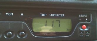
- the voltage at the generator output terminals is below 13.5 Volts;
- the indicator on the instrument panel inside the car continues to light after starting the power unit;
- the arrow on the voltmeter shifts to the red zone when readings are taken;
- The battery indicator does not light up after turning on the ignition.
Similar symptoms are detected when the voltage regulator breaks down; therefore, its serviceability is checked first. There are various reasons why a rectifier bridge fails, which requires its repair or complete replacement.
How to repair a diode bridge?
Before repairing the generator rectifier, preparation and a general check of the performance of the diodes should be carried out. The mechanism is checked in several stages:
- Disconnecting the voltage regulators and protective casing from the bridge.
- Check for short circuit using the battery and an incandescent lamp (in case of damage to the diodes, a short circuit occurs when an incandescent lamp is connected to the terminal of the battery and the generator housing).
- Checking the condition of positive and negative elements (by connecting the plus and minus terminals of the battery and generator).
- Checking the diode bridge circuit.
- Repair or replacement of non-working elements.
Since the generator diode bridge has a low cost, every car enthusiast can repair the equipment. However, manual repairs will take a lot of time, and in order not to waste extra hours searching for information on the Internet, we suggest drivers adhere to the following recommendations:
- During the repair process, you will still have to remove the diode bridge assembly.
- The constant ingress of water into the unit causes its increased wear resistance, so it is advisable to move the rectifier to another place - less susceptible to moisture ingress. Experienced experts advise protecting the on-board network with a reliable housing under the hood.
- Pressing and unpressing the rectifier yourself will be more expensive than at a service station, but the car owner will be confident in its reliability.
- Buying diodes on the spontaneous market will be cheaper, but there is a risk of parts malfunctioning.
- Before replacing the rectifier, it is necessary to remove the insulator and the old fastener element, and be sure to transfer them to the new diode bridge.
If you want to upgrade the rectifier and install three levels of a generator relay, buy three more pairs of diode bridges that will create an independent “plus”.
Important! Checking the serviceability of parts purchased on the market is quite simple: if the “ringing” of the diode in a cold state shows from 500 to 800 Ohms, and when the engine starts, a thermal “breakdown” occurs, the design is faulty.
Generator repair
In this manual we will look in detail at the VAZ 2107 - generator repair. For repairs, you will need a bearing puller, a mandrel for pressing and knocking out bearings in the generator cover. So let's get started:
Using a socket wrench, unscrew the nut securing the pulley and impeller, and use a screwdriver to hold the rotor from turning;
Unscrew the impeller fastening nut
We pull the pulley off the shaft, then the fan impeller, take out the key, take out the spacer washers;
We remove the pulley, impeller and spacers
We unhook the voltage regulator relay, first unscrew the fastening screws, and disconnect the wire block;
Unscrew the screws securing the relay
We take out the voltage regulator along with the brush assembly from the housing;
We take out the regulator and brushes
We unscrew the nuts securing the generator cover with a 10-mm socket and a ratchet, and remove the bolts;
Unscrew the nuts securing the cover
We rest the cover against a block of wood, helping by hitting the shaft with a rubber hammer, knocking down the front cover;
Removing the front cover
- Remove the cover and take out the spacer bushing;
- Check the condition of the front ball bearing. To do this, hold the cover tightly, turn and rock the bearing itself (the inner ring of the ball bearing) with your fingers. If excessive play is detected or the bearing is broken, it should be replaced with a new one;
- To replace a faulty ball bearing, use a size 8 wrench to unscrew the nuts securing it;
Unscrew the nuts to remove the ball bearing
We take out the bolts and washers
We select a suitable mandrel (punch) and knock out the bearing;
We take two wooden blocks, rest the edges of the back cover against them, and use a drift made of soft metal to knock out the rotor. If the surfaces of the lids are suddenly damaged, treat them with an abrasive wheel;
- We check the serviceability of the rear ball bearing using the method described in point 8;
- If replacement is required, remove it from the rotor using a puller;
Using a 8-mm socket with an extension and a ratchet, unscrew the nuts securing the diode block (diode bridge) and the leads from the stator winding;
Unscrew the diode bridge
- We take out the bolts and pull out the stator from the cover;
- We check the integrity of the stator winding. If the winding is damaged by mechanical action (scuffs, broken wires), or from overheating (blackened, burnt), then we replace the stator winding or rewind it, if time and price permit;
Pull out the stator winding
- Using a ratchet head, remove the generator output nut along with a washer made of an insulating substance;
- Now we can remove the diode bridge itself;
We take out the diode bridge
Using a Phillips screwdriver, unscrew the screw securing the capacitor and remove the capacitor. We remove the third bolt from the cover, which secures the rectifier unit.
Removing the third bolt
After completely disassembling the generator, we check the stator and rotor using a test lamp (watch the video). VAZ 2107 generator (repair and replacement) yourself is not such a difficult task, you no longer need the services of auto electricians. This will save you a lot of money.
Let's start assembling the VAZ 2107 generator
Before you begin assembly:
- clean all parts from dust and dirt
- blow with air using a compressor.
- It is recommended to wash metal parts with gasoline.
We press a new bearing onto the rotor using a mandrel (or head) with a diameter that matches the diameter of the inner ring of the bearing.
Press the new bearing onto the rotor
Taking both generator covers in your hands, carefully inspect the bearing seats. There should be no damage. Be sure to replace cracked lids with new ones. We perform the assembly in the reverse order, which our instructions tell you. At this point we consider the repair complete. In my opinion, everything is clear here without the video! If it’s not clear, look for the video using the keywords: VAZ, repair, 2107, generator.
One of the reasons why the battery is not charging is a breakdown of the generator. Before you independently repair the VAZ 2107 generator, you need to find out the causes of the breakdown and become familiar with the technology for removing, restoring and installing it.
How to choose a tester?
Choosing a tester is no less important than diagnosing a rectifier, and a correctly selected device is a guarantee of successful equipment diagnostics.
If in the recent past, when purchasing a multimeter, car owners were faced with a shortage of equipment, now they can be purchased in almost every store.
Earlier we mentioned the incandescent lamp and, in fact, this is the cheapest device. Such a tester is suitable for identifying small faults in the rectifier, but is not suitable for finding more complex problems. Therefore, it is recommended to purchase modern multimeters, many of which are automatic and come with LCD screens.
In conclusion, I would like to draw attention to the following things:
- every car owner should be able to check the diode bridge on the generator, since this is considered a basic skill in servicing your own car;
- “conductivity”, “tseshka” and other testers do not always show the final result even when used correctly, so it is better to diagnose a breakdown using several devices;
- in case of replacing the generator rectifier, do not forget to protect it from moisture;
- buying parts on a spontaneous market will be cheaper than in a store, but there is a risk of buying a faulty product;
- To accurately diagnose a bridge, it is better to purchase several multimerts.
The most common car malfunctions, including the VAZ 2107, include problems with electrical equipment. Since the power source in the vehicle is the generator and the battery, the starting of the engine and the operation of all consumers depend on their uninterrupted functioning. Since the battery and generator work in tandem, the service life and duration of operation of the former depends on the latter.