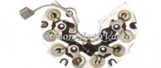
A generator diode bridge is present exclusively in “on-board power plants” of alternating current. Since most passenger cars are equipped with alternating current generators, a rectifier with diodes and a zener diode is present in each of them. Usually this unit is built into the generator, but there are remote diode bridges for convenient service, repair and replacement of diodes.
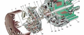
Rice. 1 The generator rectifier is a diode bridge with a zener diode
Purpose of the rectifier
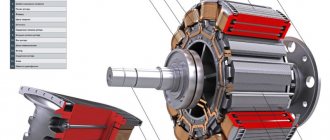
Since alternating current generators are more advanced, compact and repairable compared to direct current modifications, a generator diode bridge is added to the design by default to convert alternating current to direct current.
Rice. 2 Connection diagram of the diode block
In other words, without a rectifier assembly, electricity will be generated by the generator windings, but will become unusable for the on-board network and battery. Headlight lamps, air conditioning compressor windings and electrical circuits of other consumers will burn out, and the engine will not be able to start.
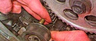
Disassembly
This section describes a step-by-step process that will help you correctly disassemble the Gazelle generator.
So, first you need to remove the plastic protective cover from the case. Then unscrew the brush block and the voltage regulator, having first disconnected the wiring from it. Next, you should unscrew the four tie rods of the generator housing and remove the housing cover together with the stator. Then, having disconnected the winding terminals from the diode bridge, you need to remove the stator, and, if necessary, the diode bridge itself.
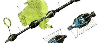
Next, remove the drive pulley and the cover with the rotor bearing from the shaft.
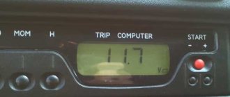
You can carry out the process of diagnosing generator parts using measuring instruments: E236 or a special test light.
Rectifier design
In the literal sense, a rectifier is not able to “straighten” alternating voltage. This unit received its name because of the operating principle of the diodes included in it:
- alternating current periodically changes the direction of movement in the circuit;
- diodes pass it in only one direction and cut off currents of reverse polarity;
- so that power surges in the network are invisible to the powered consumer, 3 diodes are installed in one direction, the remaining 3 in the other.
Rice. 3 Operating principle of the generator rectifier
Currently, high-power diodes have a classic design; low-power semiconductor devices of this type are made in the form of a silicon junction on a board. However, to remove high temperatures from the body or silicon junction, both modifications are either embedded in the heat sink plate or equipped with their own individual radiators.
Rice. 4 Power 1 and additional 2 diodes are assembled on a heat-sinking horseshoe
If a silicon junction or a full-fledged diode in the housing breaks down, the diode bridge of the generator or individual semiconductors included in its composition must be replaced.
Main diode bridge
The lower figure shows sinusoids and the direction of current movement in the generator and diode bridge.
Rice. 5 Voltage direction in AC graph and rectifier circuit
The positive value is conditionally taken to be the voltage directed to the 0 point of the stator winding. After the rectifier, the current in the consumer load flows only in the positive direction, that is, from the “+” of the generator to its mass “-”.
Therefore, the power diode bridge (main) uses large-sized 25 - 30 A diodes, the power of which can be further increased due to the additional rectifier arm discussed below.
Unlike other components of the “auto power plant”, a visual inspection does not allow us to identify any faults in the diode bridge of the generator. The rectifier requires only hardware diagnostics with a multimeter.
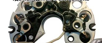
Rice. 6 Main diodes
The diodes are located on a horseshoe-shaped heat sink plate under the back cover of the generator. On remote rectifiers, the diode bridge is located near the generator; instead of plates of the classical configuration, a regular board can be used. In this case, a finned radiator is placed on the body of each diode.
Additional diodes
The main difficulty in the design of a car generator is that the excitation winding of its armature is also a consumer of constant voltage. This coil uses the generator's own diode bridge:
- 3 additional diodes cut off the battery current when the engine is not running;
- negative diodes are taken from the main (power) bridge of the generator.
Rice. 7 Additional diodes
Instead of powerful semiconductor devices, small-sized 2 A diodes are used.
Zener diode
Since the amount of voltage generated by the machine’s generator directly depends on the speed of the crankshaft, which transmits torque to its pulley, “spikes” of up to 20 V are possible in the on-board network, which is harmful for consumers. To eliminate frequent repairs, the easiest way is to connect the rectifier diode bridge via a zener diode:
- this semiconductor device cuts off current of reverse polarity by analogy with a diode, but only up to a certain value called stabilization voltage;
- when the voltage from the stator windings increases to 25 - 30 V, the zener diode begins to pass excess voltage, but in the opposite direction;
- At the “+” terminal of the generator, the correct current value for the on-board network and battery charging is maintained.
Rice. 8 Zener diode
When diagnosing a rectifier, checking the diode bridge of the generator with a multimeter is carried out indirectly:
- a normal diode should have “infinite” resistance in one direction, 500 - 700 Ohms in the opposite direction;
- If, when moving the tester probes, the ohmmeter readings do not change, the indicator displays 0 or infinity, the diode is broken and needs to be replaced.
The check is described in more detail in the following paragraphs of this manual.
Additional rectifier arm
Phase voltages are characterized by a deviation of the voltage graph from a sinusoid. Therefore, a generator circuit with an additional rectifier arm is only possible when the stator windings are connected in a star:
- the shape of the phase voltages in this case differs from the sinusoid by the harmonic value;
- this characteristic (third phase harmonic) is present only in phase voltage and is absent in linear voltage;
- The harmonic power can be used as an additional arm by adding diodes at the 0 point of the stator phase windings.
Rice. 9 Circuit with an additional rectifier arm
The magnitude of the shoulder is 5–15% of the generator power, but it occurs only at speeds above 3000 rpm. The durability of the rectifier also depends on the performance of the voltage regulator. But repairs are available to the owner of the car after disassembling the generator.
Schemes of rectifier blocks for automobile generators.
In rectifier blocks of domestic automobile generators, diodes D104-20, D104-25, D104-35 are usually used, designed, respectively, for maximum permissible currents of 20, 25, 35 A. In three-phase generators, the maximum generator current should not exceed triple the maximum permissible current through diode. So, if diodes are used with a maximum permissible current of 20 A, then when using a rectifier bridge with six such diodes, the maximum generator current cannot exceed 60 A. If a generator with a higher current is required, then you can use a rectifier unit with diodes for a higher maximum permissible current or a rectifier unit with twelve diodes.
Figure 8.1 – Diagram of a rectifier unit with twelve diodes.
It should be noted that doubling the generator current when doubling the number of diodes does not occur, since the current is distributed unevenly between two parallel diodes. From the rectifier unit shown in Figure 8.1 with 20 A diodes, you can get a current of 90-100 A. In order to provide a larger generator output current, you can increase the number of stator winding phases. The number of phases is chosen odd, for example 5,7,9 and so on. When using an even number of phases, the number of rectified voltage ripples decreases by 2 times compared to an odd number of phases, and their amplitude increases, which negatively affects the quality of the generator output voltage.
On special vehicles, a five-phase generator is used with a five-phase main rectifier bridge and a three-phase additional rectifier to power the field winding.
Figure 8.2 – Diagram of a rectifier block for a generator with five phases and an additional rectifier.
The currents in the field winding are small, so it is not advisable to use a five-phase rectifier. To power the excitation winding, a three-phase rectifier bridge is used, connected so that the voltage at its output is maximum.
Modern generators sometimes use three-phase rectifier bridges with 4 arms.
Figure 8.3 – Features of the operation of a rectifier with an additional arm.
The fourth arm is connected by input to the neutral of the stator winding and is used to rectify higher harmonics. The fact is that in a real generator the shape of the phase voltage differs from the sinusoid. It represents the sum of harmonics - the first, the frequency of which coincides with the frequency of the phase voltage, and the highest, for three-phase generators, mainly the third.
Figure 8.4 – Phase voltage
as a sum of sinusoids of the first and third harmonics.
A shift of 120° between the phases of the generator for the first harmonic corresponds to a shift of 360° for the third harmonic, 720° for the sixth harmonic, and so on for harmonics that are multiples of three. Therefore, third harmonics and harmonics that are multiples of three different phases of a three-phase generator have vectors directed identically (
and in Figure 8.3, a
). In line voltages, which are the vector sum of two phase voltages, harmonics that are multiples of three are destroyed ( ). A conventional rectifier does not rectify third harmonics as it rectifies line voltage.
In order to use the power developed by the third harmonic, an additional arm is added to the rectifier. This arm is connected to the neutral point of the stator winding (see Figure 5.8, b
). Thus, phase voltages are supplied to the input of the rectifier unit, which contain harmonics that are multiples of three. Therefore, the rectifier shown in Figure 5.8b additionally rectifies harmonics that are multiples of three. The use of an additional arm increases the generator power by 5–15%.
Expensive cars are equipped with complex electronics that are very sensitive to overvoltages. To get rid of overvoltages, instead of diodes in the rectifier block, zener diodes are used, the stabilization voltage of which is 1.5 times greater than the generator voltage.
Rectifier faults
Since the generator rectifier assembly consists of several semiconductor devices and is protected by a cover in 90% of cases, diagnostics will require electrical tools and partial disassembly of the generator. However, in some cases, the driver can hear signs of a diode bridge malfunction:
- when pulsations occur (alternating voltage is supplied to the on-board network instead of direct voltage), the electric motors of some consumers can reproduce sounds by analogy with a speaker;
- Most often, the drive of the power windows and stove “squeaks”, and the tone changes when the speed of these devices changes, and not the crankshaft speed.
In all other cases, malfunctions of the vehicle generator in the rectifier assembly are diagnosed exclusively by instruments. To do this, you will need a diagram for connecting the diode bridge in a specific modification of the generator, since the symptoms of a mechanical failure are completely similar to the breakdown of electrical parts.
Diagnostics of breakdowns
The rectifier assembly is assembled using various technologies - some parts are attached mechanically, small diodes are soldered into the circuit, large ones are usually pressed in. Therefore, repair of the rectifier may be required, not only if the semiconductor elements fail, but also if they are installed incorrectly on the “horseshoe” of the heat sink plate.
Before ringing a circuit or individual semiconductor, you should visually inspect the structure. Even in the absence of a tester, ohmmeter, or voltmeter, you can use a light bulb and a special battery connection diagram to understand whether the diode is faulty or working correctly.
The diagnostic technique is as follows:
- the back cover is removed from the generator to provide access to the diodes;
- the plate is supplied with a “–” wire from the battery, it is pressed against the housing on the generator, one wire of the lamp touches the diode at the point where the stator winding is connected, the second – to the “+” of the battery, if there is a breakdown, the light will light up;
- The tester is set to 1 kOhm ohmmeter mode; if you swap the multimeter probes, the readings should change from 0 to 400 - 800 Ohms in different directions.
Rice. 10 Diagnostics of the rectifier with a lamp
Rice. 11 Diagnostics with a multimeter
In most cases, the diode bridge burns when moisture penetrates.
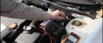
Diagnostics
Replacing the diode bridge of the generator on a VAZ 2112.
A often burnt-out diode bridge of the generator creates many problems. Because of this, the battery does not receive the required amount of current or, on the contrary, it receives much more of it than it should, and overcharging occurs. Before replacing this component of the generator, it is advisable to carry out proper diagnostics.
Diode bridge diagnostics
Note. It is important to know that alternator rectifier diodes are like a one-way valve that allows charge to flow in only one direction. Thus, the access of current from the on-board network to the starter windings is closed.
- If a semiconductor diode conducts current in both directions or does not conduct charge at all, then it is faulty.
- The cause of diode burnout may be moisture or improper battery charging in the winter.
Check algorithm
Replacing the diode bridge on a VAZ 2112 generator.
We remove the diode bridge to carry out the test - this is extremely important. How to do this will be described in detail below:
Generator rectifier block
- Take a multimeter and set it to diode test mode.
- First, we connect the plus probe to the common bus of auxiliary diodes. As for the negative terminal, it should be connected to the terminal of the diode being tested.
- The result will be positive (implying the health of the diode) if the device readings tend to infinity.
- Now you need to swap the probes. If the diode is working properly, the multimeter readings will show several hundred ohms.
Note. In the same manner we check two additional diodes of the unit.
- The minus probe is placed on the plate of the diode bridge, in the place where the diode is pressed in. The positive probe should go to the diode terminal.
- The result can be called positive if the diode does not allow charge to pass through, and the multimeter readings tend to infinity.
- Again we swap the probes.
- A positive result if the device shows a resistance of several hundred ohms.
VAZ 2112 diode bridge generator
Note. The remaining power diodes are checked in the same way.
Repair and replacement of diode bridge
Since the rectifier device is simple, and the cost of the entire unit is low, the choice of repairing or replacing diodes depends mainly on the availability of free time from the car owner:
- You will have to remove the rectifier assembly in any case;
- Replacing a generator with your own hands will cost a little more, but it will be faster;
- knocking out and pressing in new diodes takes longer, but is cheaper financially;
- if moisture gets on the rectifier assembly regularly, it is easier to remove the diode bridge and take it to a separate unit under the hood, protecting it with a homemade housing, since a working on-board network is worth the time spent.
The main mistake when replacing the “horseshoe” of the generator rectifier is shorting the two plates with a bolt. This fastener is swapped from the old diode bridge, and the insulator remains in the square mounting hole. It must be removed and moved to a new location before replacing the diode bridge.
Rice. 12 The insulator under the bolt must be moved to the seat
There are dielectric spacers (getinax or textolite) on the three screws securing the stator windings. The fourth screw without a similar washer is attached to a hole specially designed for it, so it is better to remember its location before removing it.
Rice. 13 One screw is installed without a dielectric washer
When purchasing diodes secondhand on the market or after installing a set of semiconductor devices from your own supplies, their malfunction may be detected:
- in a cold state, the diode “rings” normally (resistance 500 - 700 Ohms in one direction, infinity in the opposite direction);
- After starting the internal combustion engine, when the bridge is heated, the diode “breaks through” and does not cut off the negative voltage value.
Therefore, before checking the diode bridge of the generator with a multimeter, it is better to do it in a state heated to 50 - 80 degrees.
Design features
- In the factory version, diode bridges for the VAZ 2110 are monolithic structures that are distinguished by their reliability, affordability, and compact size;
- The factory diode bridge has only one significant drawback - if one diode burns out, it is not possible to replace one element. You have to buy a new factory rectifier and replace it with the old one;
- If the diode bridge fails, you can try to assemble it yourself from different diodes;
- In the factory version, the rectifier has 4 or 6 diodes, and if you manufacture it yourself, you can add one additional one. Many people do this;
- When installing an additional diode, they do not use factory elements, but more powerful ones. This allows them to not burn out for a longer period of time.
Pinout of Lada Priora comfort block
It is difficult to check the quality of operation of a homemade rectifier, which is why interfering with the factory design can only harm the generator. Then, instead of buying cheap consumables, you will have to change almost the entire assembly.
Location on generator
Installing a dynamo on the engine
Installation on the engine is carried out in compliance with a certain technological process.
First, unscrew the fastening nuts of the generator brackets to the crankcase. Next, install the dynamo and secure the front mounting bolt. Then we move the front bracket and achieve alignment of the crankshaft ratchet with the drive flywheel of the part and the pump drive. By moving the bracket, we achieve elimination of the gap between the generator loop. Install the rear mounting bolt and firmly tighten the mounting nuts of the brackets to the engine crankcase. Next, we put the drive belt on the pulleys and tighten it using a tension bracket. We carry out a control check of the tightness of all threaded connections. We connect the part to the car's electrical network and put the terminals on the battery.
Therefore, solving such an issue is not particularly difficult, and besides, the process itself takes a small amount of time. You can save a lot on auto mechanic services.