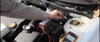
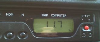
The electrical equipment of a modern car is a complex set of instruments and devices. The on-board power supply is supplied from the battery, and after starting the engine - from the generator. This device, in good condition, provides a voltage within 14 - 14.2 V. Checking the VAZ 2107 generator will not only help identify its malfunctions, but also avoid battery failure.
If the voltage is insufficient, its charge becomes incomplete, which causes a drop in the density of the electrolyte. At low temperatures, this phenomenon can cause the liquid to freeze. The formation of ice crystals leads to the gradual destruction of the battery plates. To establish the output voltage parameters of the generator, you can ring it with a conventional multimeter.
Checking the generator with a multimeter
The electrical equipment of a modern car is a complex set of instruments and devices. The on-board power supply is supplied from the battery, and after starting the engine - from the generator. This device, in good condition, provides a voltage within 14 - 14.2 V. Checking the VAZ 2107 generator will not only help identify its malfunctions, but also avoid battery failure.
If the voltage is insufficient, its charge becomes incomplete, which causes a drop in the density of the electrolyte. At low temperatures, this phenomenon can cause the liquid to freeze. The formation of ice crystals leads to the gradual destruction of the battery plates. To establish the output voltage parameters of the generator, you can ring it with a conventional multimeter.
In what situations is replacement necessary?
Wear of the element is characterized by such manifestations as cracks or tears in the canvas, worn teeth and uneven edges. If you ignore such a deplorable state of a very important element, it will come back to haunt you with overheating and boiling of the engine, independent operation of the battery, which will lead to its rapid discharge.
If the belt is severely worn, it also shows signs of noise to the owner - it begins to whistle, especially at low speeds. The next reason for a whistling belt may be water getting on its surface, which occurs due to worn-out pipes of the cooling system - antifreeze begins to leak.
Some belts - oak ones - whistle when the car starts in frosty weather, and after warming up the sound is lost. A weak tension is expressed by a whistle, but in this case it is quite easy to overtighten.
how to remove the generator
from a
VAZ
of the traditional model range.
More details: 2107
.html Subscribe!
Checking the voltage regulator relay
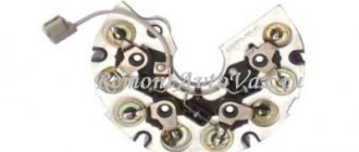
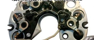
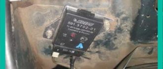
If everything is in order with the stator winding, then we move on to checking the voltage regulator, which is usually attached to the generator itself and is usually a dark box with terminals and often looks like this:
When you remove it, you will see the black carbon brushes of the generator; you also need to visually inspect them to see if they are purposeful and press them inward with your hand. Serviceable brushes should move freely along the channels and should protrude outward by about 5 mm; if their protrusion is much less than 5 mm, then they are worn down and the voltage regulator needs to be changed.
There are two ways to test the voltage regulator.
1) Check without removing the generator from the car (an assistant is needed) 2) And by removing the generator and disconnecting the regulator from it
The first way to check, with an assistant
You can check the generator without removing it from the car. To do this you need to start the car. Then we take a multimeter and turn it on to measure the voltage (select a measurement limit of 20 Volts or more). We measure the voltage at the battery terminals with the device; at idle it should be within 14 Volts, plus or minus 0.3 Volts. Now we ask the assistant to press the gas pedal. And again we look at the multimeter readings. The voltage on the device screen should not change by more than 0.5-0.6 Volts. If the difference is much greater, then the regulator is faulty and needs to be replaced.
Second way to check (with the generator removed)
To do this we need two additional voltage sources. One with a voltage of 12-13.5 Volts, and the second with a voltage of 16-20 Volts. For the first of them, a car battery is suitable, and the second source can be obtained using the same battery if you connect a couple of ordinary AA batteries in series with it.
Something like this picture:
Be careful when doing this check! Or use fuses in the circuit to prevent short circuits and fire. . 1) Connect the plus of the battery to the regulator terminal, and the minus of the battery to the regulator body
And we connect a 12 volt car light bulb to the brushes. If the regulator is working, then we will see that the light will light up
1) Connect the plus of the battery to the regulator terminal, and the minus of the battery to the regulator body. And we connect a 12 volt car light bulb to the brushes. If the regulator is working, then we will see that the light comes on.
2) The second stage of testing: we take the same battery, connect a pair of batteries in series to it, observing the polarity, so that the output voltage is from 16 to 22 Volts. And we do the same thing as in point 1. This time, the light bulb connected to the brushes should not light up. If it does not light up, then the regulator is working. And if the light comes on again, then the generator needs to be replaced with a new one.
If you have any questions, this video will help you understand how to do this check correctly:
We checked the stator coil and the relay regulator, now we also need to check the diode bridge.
Checking the serviceability of the generator rotor of VAZ 2108, 2109, 21099 (37.3701) cars
A malfunction of the generator rotor of VAZ 2108, 2109, 21099 (37.3701) cars primarily leads to the disappearance of the charging current and discharge of the battery. On the instrument panel after starting the engine, the battery discharge light will be constantly on, indicating that there is no charging current. The voltmeter needle is in the red zone or on the border with it. If you check the voltage at the battery terminals with a voltmeter (multimeter, tester, etc.) while the engine is running, it will be below the required 13.6 V. Tools required to check the rotor
Multimeter, tester, voltmeter, etc.
If they are not there, then the control lamp is a 1-5 W, 12 V light bulb with wires soldered to it .
Checking the generator rotor of VAZ 2108, 2109, 21099 cars
Checking for short circuits and open circuits can be done without removing the generator from the engine or removing the rotor. We remove the voltage regulator and, through the window that opens, carry out the manipulations described below.
Checking the short circuit of the rotor excitation winding to ground
— We press the plus of the multimeter in ohmmeter mode one by one against the slip rings, and the minus on the generator housing (“ground”).
If the rotor is working properly (there is no short to ground), the resistance should tend to infinity.
When using a test lamp, it is necessary to pass through it, in turn, the plus from the battery to each of the contact rings of the “excitation” winding of the rotor. The minus will be the generator housing, since it is installed on the car and connected to the battery negative. If the rotor is working properly, the control lamp should not light up - plus and minus do not appear anywhere. Otherwise it will burn.
checking the excitation winding of the generator rotor 37.3701 of VAZ 2108, 2109, 21099 cars for a short circuit
Next, we check the “excitation” winding for a “break”.
The plus of the multimeter (in ohmmeter mode) is on one contact ring, the minus on the other.
When the excitation winding is in good condition, the resistance is in the range of 5-10 Ohms.
If a test lamp is used, then we connect the plus from the battery through it to one contact ring, and the minus with another wire to the second contact ring. The lamp should be on. If this is the case, then the “excitation” winding is working.
checking for a “break” in the excitation winding of the generator rotor 37.3701 of VAZ 2108, 2109, 21099 cars
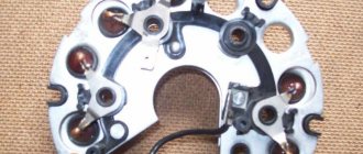
The rotor winding leads that have come off the slip rings can only be seen after removing and disassembling the generator. In some cases they can be soldered. Most often, the faulty generator rotor 37.3701 of VAZ 2108, 2109, 21099 cars should be replaced.
winding terminals and contact rings of generator 37.3701 for VAZ 2108, 2109, 21099 cars
Notes and additions
— Usually, when looking for problems in the operation of the generator, the fault of the rotor is the last thing to start sinning. Similar symptoms (the discharge light is on, the voltmeter needle drops, low voltage) can occur if the voltage regulator or diode bridge is faulty. First of all, you should check them, then start checking the rotor.
Five more articles on electrical equipment of VAZ cars
Types of relay-regulator
To exaggerate, there are only two types, but each works on the same principle, namely, “cuts” or increases the voltage to the desired level.
Combined with brush assembly. Usually it is mounted on the generator itself, in the housing where the brushes are located, there is also a relay regulator.
Separate. Usually it is mounted on the car body, the wires go from the generator to it, and only then to the battery.
The housings are non-separable and tight and of a different type (often filled with sealants or special adhesives), that is, they cannot be repaired. To be honest, they are quite cheap, especially for our VAZs, so it’s easier to buy a new one than to tinker with an old one.
These are the most common types, of course, previously there were so-called ones combined with terminals, but they didn’t catch on because the device is not very convenient, so I won’t talk about them.
If your relay is “broken” and is constantly recharging, then it’s worth changing it, but first you need to make sure that this is the problem. Now there are only two ways to check: - without removing it on the car itself, and checking an already removed relay. Let's look at both options.
How to increase on-board voltage
Where and how is a diode placed in the LV circuit on the generator in order to increase the voltage in the car network and better charge the battery? Here I propose a simple solution, raising the on-board voltage, without going anywhere in the car and its circuits. I searched in my archives and did not find the material from which I read this decision. “Structurally, voltage regulators have an upper limit of 13.6V. This is due to the “old” connection diagram, from which the new one was copied and “successfully improved”. In it, the necessary voltage from the on-board network, supplied to the regulator for comparison, passed through a chain of wires. On them it dropped to normal. According to the new scheme, we have a chronic undercharge of the battery. Which, with the arrival of winter, makes starting the engine in the cold quite problematic. But if you install a pre-heater, starting the engine will be much easier.
It should also be noted that the battery begins to absorb energy (charge) only when its temperature is above zero. Therefore, in winter, if you make short runs and the battery does not have time to warm up under the hood to at least zero (plus charging time), it will be constantly discharged. And soon it will die... It is believed that after starting the engine, in order for the battery to recover, you need to drive for at least 20 minutes. Just go, and not stand in traffic jams! How to increase the voltage in the network?
Very simple! It is necessary to make the regulator “think” that we have low voltage in the network. Thus, the generator will give us the missing volts. A diode will help us do this. In a generator with a built-in voltage regulator, you need to place a diode in the circuit, as shown in the figure.
Common breakdowns
Generator faults can be electrical or mechanical. These include:
- loss of functionality of the voltage regulator;
- breakdown of the rectifier unit (diode bridge);
- short circuit of stator windings;
- current short circuit in the rotor winding;
- wear of bearings and brushes.
Read also: B20100g datasheet in Russian
Voltage regulator
The purpose of this unit is to normalize the voltage before feeding it into the automotive electrical circuit. You can check the serviceability of the regulator by checking the voltage that it supplies to the battery terminals. This indicator depends on the model and brand of the vehicle and varies between 13.5-15.5 V. Therefore, you should find out in advance what voltage your particular type of regulator produces. This can be done by studying the manual for using the machine. For example, you can take a VAZ 2107 or 2110 car, since these vehicles have the most typical faults associated with the integral and relays.
Using a Multimeter
To check the VAZ 2110 generator with a multimeter, you need to switch the device to voltmeter mode. Then you need to connect its probes to the battery terminals. The most important thing is to observe the polarity and turn off the car engine. The voltage normally varies from 12 to 12.8 V. Next, the procedure should be repeated, but with the engine running. The voltage readings should rise to 13.5-15.5 V. Lower and higher voltage values indicate a malfunction of the generator.
Checking the generator without removing it from the car
A bridge of diodes performs the functions of a kind of alternating current converter. It contains three negative and three positive diodes.
Before checking the bridge, you need to disconnect all the wires coming from it and from the voltage regulator. You also need to remove the ground anchor from the battery in advance. First you need to check the rectifier for short circuits. We activate the ohmmeter mode on the multimeter and connect the red (positive) probe to the positive contact of the diode bridge, and the negative probe to the surface of the housing of the generator itself. If the rectifier is fully operational, then the readings of the measuring device will go to infinity. In other cases, the rectifier will be inoperative.
Testing of stator and rotor windings
A common breakdown of a car generator is a short circuit in the windings. It occurs when current surges are too intense, brushes wear out and liquid gets in.
So, you need to remove the rotor and find a pair of slip rings on its structure that will need to be ringed. Having started the ohmmeter mode on the multimeter, we connect the probes to these rings. Normal resistance is 2-6 ohms. If you get large values, then there is a loss of contact between the slip rings. If the device shows lower values, then an interturn short circuit has occurred.
Then you should measure the resistance between zero and the terminals of the windings. The normal value is no less than 0.3 Ohm.
Wear of brushes and bearings
If you have already disassembled the generator, then it is advisable to check the condition of the brushes. They can wear out or break due to misalignment of the rotor shaft. If the brushes are damaged, they should be replaced with new ones.
Inside a car alternator there is a pair of bearings. One is fixed on the rotor shaft, the other is in the center of the cover. The whistling and hum of the generator when the engine is running is a clear sign of bearing wear. In this case, the generator housing can become very hot. If you notice such signs, it is better to replace the bearings immediately, otherwise you may encounter more serious problems.
You can check the bearing by removing the belt from the generator and trying to rotate its shaft with your own hand. If the part rotates freely and easily, then everything is in order. If it is difficult to rotate the rotor, then you should not delay replacing the bearings.
How to check the generator for performance? Self-check and repair of the generator
A generator is a typical electrical station that provides energy to all engine systems: power, cooling, ignition, so its failure will inevitably lead to other malfunctions. To prevent breakdowns, you need to systematically diagnose it, and if problems cannot be avoided, repair it immediately.
In this article we will talk about how to check the generator for performance without resorting to the help of professionals. But before that, let's look at the symptoms of its possible defects.
Read also: How to make a snowmobile from a trimmer with your own hands
What generators can be installed on the “seven”
The design of the VAZ 2107 allows the installation of not only the G-221A generator. Therefore, if necessary, the driver can install a more efficient device, but in this case some changes will have to be made to the electrical circuit of the car. The question arises: why should a motorcyclist even change his “original” generator?
The G-221A was the optimal device for equipping cars at the beginning of mass production. However, a lot of time has passed since the 1980s, and today almost every motorist uses modern electronic devices:
- sound systems;
- navigation systems;
- additional lighting devices (tuning), etc.
Accordingly, the G-221A generator cannot cope with heavy loads, so drivers begin to look for more powerful units.
At least three more powerful units can be installed on the “seven”:
- G-222 (generator from Lada Niva);
- G-2108 (generator “eight”);
- G-2107-3701010 (Car injection model with carburetor).
It is important that the last two models do not require changes in the design of either the generator housing or its mountings. If you are installing a Niva generator, you will have to make some changes.
Video: principle of operation of the generator
Connection diagram G-221A
As an electronic device, the generator must be used correctly. Accordingly, its connection diagram should not cause misunderstandings. It is worth noting that the “seven” drivers can easily connect all the generator terminals on their own, because the circuit is accessible and understandable to everyone.
Many car owners wonder where to connect which wire when replacing the generator. The fact is that the device has several connectors and wires, and when replacing it is easy to forget which wire goes where:
- The orange one is useless for wiring, you can leave it as is or connect it directly to the gray one to start automatically;
- a thick gray wire goes to the brushes from the voltage regulator;
- the gray thin wire goes to the relay;
- yellow wire - coordinate indicator lamp on the control panel.
How to test a generator with a multimeter
The diode bridge of the generator can be checked with a multimeter, but you can also use the stand that was used to check the regulator.
But before that, first of all, without removing the rectifier bridge from the generator, connect the red wire of the tester to terminal 30 of the generator, and the black wire to the housing. Set the tester operating mode to dial (diode icon). If it is not there, then set it to 1-2 kOhm. The multimeter should show infinity. If the readings are different, the diode bridge is faulty.
Then check the current rectifiers for breakdown. Leave the positive (red) probe on terminal 30, touch the negative one to the bridge mounting bolts one by one. The multimeter display should show infinity in all cases; any others mean a breakdown.
Next, connect the positive probe to the axle mounting bolts, and the negative probe to the generator housing. In this case, the tester should also output infinity.
But in practice, such verification is most often not enough. In most cases, it is necessary to ring the generator in more detail.
Careful testing
To do this, unscrew the fastening bolts of the rectifier unit, disconnect the copper wires of the stator winding and remove the diode bridge from the generator. Now you can test each semiconductor individually. Before checking, it is advisable to rinse the stabilizer with running water using a medium-hard brush, and then dry thoroughly. For quick drying, a hair dryer is quite suitable.
Attach one of the tester probes to the diode plate, connect the second to the central terminal of each diode fixed to this plate. Then swap the probes. In one case, the multimeter should show infinity, in the other - a nominal resistance of approximately 570-590 Ohms. Rectifiers are considered faulty if:
- In the first and second measurements (when the polarity was changed), the multimeter readings are the same;
- Diode resistance is greater or less than nominal values.
Perform the same actions with the second plate of the diode bridge. If a fault is detected in one or more diodes, it will be easier to replace the entire rectifier unit. True, there are craftsmen who replace failed diodes individually, but such work requires a certain skill and dexterity.
Checking the armature and stator windings
Further inspection requires completely disassembling the generator. First of all, visually check the anchor. Brush rings should not show any blackening, chipping or wear on the treadmills. Blackening and slight wear can be smoothed out with zero-grade emery cloth. Rings with deep grooves must be replaced or, if the thickness of the rings allows, turned on a lathe.
The armature winding should not clearly smell like burning. The color of the winding must be uniform and free of damage and breaks. To check the armature winding for a break, you will need a multimeter. Set the operating mode to continuity testing or resistance measurement and connect the probes to the brush rings. The winding resistance should be within 3-5 Ohms. Then leave one probe on the ring, connect the other to the body. The multimeter display should show infinity.
The generator stator is diagnosed after removal from the housing. First of all, carry out a visual inspection. There should be no visible damage to the wire or its insulation. Then connect the tester wire to the stator housing. With the second wire, touch the terminals one by one. There are only three of them. The tester must be in dialing mode. If the display shows infinity, this indicates that the stator is working properly.
Further testing consists of diagnosing the windings. The resistance of all three windings must be the same.
Before assembling the generator, you need to check and, if necessary, replace the bearings. When turning, they should not jam or make a creaking sound. This means that they are very worn out and will soon fail. Therefore, it is better to replace them immediately.
Description of the generator armature
An assistant will be needed to perform this operation. Sequence of actions to check the functionality of the generator:
- Set the digital or indicator multimeter to DC voltage measurement mode. We check the parameters at the battery terminals. According to the instruction manual, the voltage should be in the range from 11.9 to 12.6 V, perhaps a little less, taking into account the fact that the network consumes a small amount of energy.
- The assistant starts the engine and leaves it running at idle speed, we check the voltage again. If it drops, this means that the generator either does not work completely, or the parameters are insufficient to charge the battery.
- Exceeding the voltage value of 14.5 V for a long time will lead to boiling of the electrolyte in the banks.
If a generator malfunction is detected, you will need to check the diode bridge, electronic voltage regulator, stator and rotor windings, as well as the condition of the brush assembly.
To perform this operation, it is necessary to remove the device from the vehicle and clean it of dirt. The verification procedure is as follows:
- We switch the multimeter to resistance measurement mode. We install the positive probe on terminal “30”, and the negative probe on ground. Readings close to zero indicate that the bridge or generator stator has failed.
- Positive diodes are checked by installing a positive probe on the terminal of one of the rectifier unit mounting bolts, and a negative probe on ground. Zero or close to zero instrument readings indicate that the diode bridge is faulty.
- To check the rotor, it is necessary to measure the resistance between the slip rings. In working condition it should be within a few ohms. If the resistance is near zero, then a short circuit has occurred in the winding.
The diode bridge and other faulty elements of the generator must be replaced with new ones from spare parts.
There are hardware and visual ways to check a car's generator. However, the owner must know the design and purpose of this electrical device in order to diagnose correctly. This guide will help you avoid a trip to the service station and save your operating budget.
Rice. 1 Checking the car generator
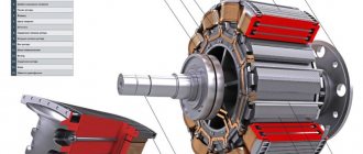
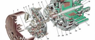
Before you test the generator with a multimeter on your own, you need at least minimal knowledge about the design of the electrical appliance:
- the belt transmits rotation from the engine crankshaft to the generator pulley
- mechanical energy is converted into electrical energy
- diode bridge changes alternating current to direct current
- The regulator relay is responsible for recharging the battery when it is discharged during engine startup
- the rest of the voltage is spent on electrical appliances of the machine
Rice. 2 Design of a car generator
Both undercharging and overcharging are harmful to the battery, so the voltage at the terminals must have stable characteristics at any speed. At the same time, the connecting unit, dimensions, layout and quality of manufacture of generators may differ significantly from different manufacturers and for specific car modifications.
Circuits and terminals
Before you check the generator on your car on your own, you need to know the electrical diagram of this unit and the purpose of the terminals on its body. The most popular are 6 schemes; for example, one of them is shown in the bottom photo.
Rice. 3 Example of electrical circuit
For ease of reference, the digital designations on all diagrams are the same:
- generator block
- exciting winding
- stator winding
- rectifier
- switch
- warning lamp relay
- voltage regulator
- indicator lamp
- noise suppression capacitor
- transformer/rectifier unit
- battery
- zener diode
- resistor
The terminals on the case are not designated the same, which may interfere with correct diagnostics with a multimeter (tester):
- positive terminal of the power rectifier - VAT; IN ; thirty; B or ""
- exciting winding – FLD; E; EXC; F; DF; 67 or Ш
- output for the control lamp from the backup rectifier – IND; W.L.; L; 61; D or D
- phase – STA; R; ͠ or W
- zero – MR or “0”
- output for "" battery - B; 15 or S
- terminal for connection to the on-board computer – F or FR
- output to ignition switch – IG
Rice. 4 Location of pins on the housing
In the Russian Federation, generators are most often used, the exciting winding of the voltage regulator of which is connected to the on-board network by the negative side. Although there are variants attached to it with “ ”.
In cars with diesel internal combustion engines, two-level 14/28 V power plants can be installed. Checking these generators is more difficult; it is better to carry it out at a service station.
The simplest option for checking a generator at home without a trip to the service center is a visual inspection and searching for extraneous sounds. However, these methods cannot identify all existing defects.
For example, the glow of a lamp on the dashboard indicates that the battery is not being recharged. In this case, the battery itself may be faulty or the generator is supplying insufficient voltage to its terminals.
Therefore, it is better to arm yourself with a tester or its more modern version of small dimensions - a multimeter for high-precision diagnostics. Most breakdowns can be identified locally; to find and repair the rest, you need to check the removed generator by partially disassembling it.
In order for diagnostics to be safe for the user and the electrical part of the car, the following conditions must be met:
- using a tester, multimeter or instruments to measure current, voltage and resistance separately
- additionally disconnecting the battery from the on-board network and from the generator
- when replacing wiring, maintain the length and cross-section of the cable as the original parts
- make sure the belt tension is normal
It is prohibited to perform the following actions:
- use sources with voltages greater than 12 V
- turn off consumers when the engine is running and the generator belt drive is connected
- connect to ground or terminal D (67) pin B (aka 30)
- check the spark to the body with a short circuit
General recommendations and nuances
It often happens that the generator stops functioning only when the engine is warm. This phenomenon is due to the natural expansion of the metal with increasing temperature or a change in the properties of semiconductors (diodes) for the same reason. In this case, you should first check the functionality of the generator on a warm car, and if this does not bring results, then dismantle the device and check it after heating it with a hair dryer. In conclusion, it is worth noting that independent replacement of generator components such as stator or rotor windings and bearings in domestic conditions is advisable only if you have the appropriate equipment, tools, and experience. If it is not there, then if the battery is not charging, limit yourself to trying to replace the relay-regulator combined with the brush assembly. To do this, you don’t have to buy a new device: you can install a known good one and evaluate the result.
Self-diagnosis
So we smoothly approached the issue of verification. If you don’t know how to check the functionality of a unit in your car, then first of all carry out a visual diagnosis of the device’s condition. If the check shows that there is no external damage, then a more thorough diagnosis is needed. Initially, you should check the winding for insulation damage; you will need a multimeter or a test lamp to check.
Before checking, one wire from the lamp must be connected to the armature shaft, and the other wires must be touched in turn to the collector plates. Please note that when checking, the wire tips must be reliably insulated. In the event that the armature winding shorts to ground, the light should blink.
To check the turn-to-turn short circuit you will need a special induction device. The core of the device in this case is made of metal, and the coil is powered using industrial alternating voltage. The armature is installed in the prism of the core, after which it must be rotated around its axis, and an iron plate must be connected to the metal. In the absence of short circuits, there will be no current in the winding (the author of the video is the Ramanych channel).
If there is a short circuit, then an electromotive force will be recorded in the closed turns. In this case, the alternating voltage will contribute to the formation of another magnetic field, so if there is one, then vibration will appear in the iron plates connected to the armature. The presence of vibration may indicate that there is a short circuit in the turns; if this is the case, then the only option to solve the problem is to rewind the armature.
Checking with a multimeter without dismantling
You can check the condition of the relay using a multimeter. In this case, the generator is not dismantled. Before starting diagnostics, it is enough to clean the battery terminals (their oxidation can affect the operation of the car and the readings of the measuring device).
The diagnostic procedure is as follows:
- First you need to start the engine and let it warm up for a few minutes.
- Next, you need to connect the multimeter probes to the battery terminals. The device displays a value of 20V.
- After this, the voltage is measured. It should be within 13.2-14V. Such readings are considered normal for most cars.
- Now you need to increase the engine speed (up to 2-2.5 thousand). The voltage should increase by about 0.2V.
- If it exceeds 3,500 rpm, the multimeter should show 14-14.5V, but no more.
Serious deviations in the readings of the device indicate the presence of breakdowns of the relay regulator.
General useful information
Checking and repairing the VAZ 2107 generator
The VAZ 2107 generator converts the mechanical energy of rotation of the engine crankshaft into electrical energy. It is also intended to power the entire on-board network, and is also necessary to recharge the battery. To convert alternating current to direct current, the unit is equipped with a rectifier unit, which consists of six diodes. A special relay-regulator serves to maintain the voltage at a given level. This device is located outside the generator.
When the ignition is turned on, the voltage, passing through the vehicle's warning lamp, reaches the regulator, and from it is transmitted to the excitation winding. It is powered by three diodes. They are located in the rectifier block. If the warning lamp continues to light during startup, this means that the battery is not sufficiently charged. You need to check the voltage status of the on-board network. If it is below normal, it means:
- a short circuit has occurred in the network;
- there are faults in the battery;
- a malfunction of the automobile relay-regulator has occurred;
- malfunction of the VAZ 2107 generator.
In this situation, you should check the belt tension, as well as the condition of its bearing, and see if the relay regulator is working. It would be a good idea to look again at the expiration date and actual condition of the battery. If everything is normal, but the voltage is not enough, you need to contact a specialist auto electrician. The generator of the presented car model does not require special care. You just need to make sure that water and dirt don’t get on it.
You should also check the condition of the belt (it needs to be tensioned, approximately as in the video), and it is also important that the bearing is constantly lubricated and does not create noise during operation
Types and location of voltage regulators
As you know, the VAZ 2107 car began to be produced a very long time ago. And over the years, not only different motors were installed on it, but also different voltage regulators. On the earliest models, the relay regulators were external. On later “sevens” the regulators were internal three-level. Let's take a closer look at these devices.
External voltage regulator VAZ 2107
It is the external voltage regulator that many motorists in the old fashioned way call a “relay-regulator”. Today, external voltage regulators can only be seen on very old “Sevens” produced before 1995. These cars were equipped with an old generator model 37.3701, which was equipped with external relays.
External relay regulators were installed on the very first VAZ 2107 models
The external regulator was located under the hood of the car; it was mounted on the left front wheel arch of the car. As a rule, external relays were made on the basis of a single semiconductor, although after 1998 on some VAZ 2107 there were external regulators made on a common printed circuit board.
The external regulator was not built into the generator, but was located under the hood of the car
External relays had certain advantages:
- Replacing the external regulator was fairly easy. It was held on by only two bolts, which were not difficult to reach. The only mistake that a beginner could make when replacing this device is to mix up terminals 15 and 67 (they are located next to each other on the regulator);
- the cost of the external regulator was quite affordable, and they were sold in almost all car stores.
Of course, the device also had disadvantages:
- bulky design. Compared to later electronic regulators, the external relay seems very large and takes up too much engine compartment space;
- low reliability. External VAZ regulators have never been of high quality. It is difficult to say what is causing this: the low quality of individual components or the poor build quality of the device itself. But the fact remains a fact.
Internal three-level voltage regulator
Internal three-level voltage regulators began to be installed on the VAZ 2107 starting in 1999.
The internal regulator began to be installed on the VAZ 2107 after 1999
These compact electronic devices were built directly into car generators.
The internal regulator is mounted directly into the VAZ 2107 generator
This technical solution had its advantages:
- compact sizes. Semiconductors were replaced by electronics, so now the voltage regulator fits in the palm of your hand;
- reliability. It’s simple: there’s nothing special about electronic devices that breaks. The only reason why a three-level regulator could burn out is a short circuit in the on-board network.
There are also disadvantages:
- difficulty of replacement. If there were no particular problems with external regulators, then to replace the internal relay the car owner first needs to get to the generator. To do this, he will have to remove the air filter and a couple of air ducts, which requires patience and time;
- difficulty of acquisition. As you know, the VAZ 2107 has long been out of production. So getting new components for the “seven” is becoming more and more difficult every year. Of course, this rule does not apply to all details. But internal three-level voltage regulators for the VAZ 2107 are among the parts that are not so easy to find today.
This is interesting: Checking diesel engine injectors, malfunctions and cleaning
Rectifier block
| Control and signaling panel for the filter unit ARS-250 (400.| Boost-rectifier unit with high-voltage switchgear. |
The rectifier unit is assembled from selenium rectifiers using a single-phase bridge circuit, each arm of which consists of 39 blocks of 70 rectifier washers with a diameter of 30 mm with a permissible voltage of 20 V and a current of 300 mA. The high-voltage switchgear (RU-80), designed for a voltage of 80 kV and a load current of up to 1000 mA, is intended for connecting high-voltage circuits of an electrostatic precipitator. The device body is mounted on the cover of the boost-rectifier unit.
The rectifier unit and transformer are cooled by a fan.
The rectifier unit consists of a transformer with a 110 V primary winding and a selenium rectifier composed of several groups of selenium washers.
| Tractor valve generator. / — regulator block. 2 - stator. 3-rotor. 4-excitation winding. 5 - rectifier block. |
The rectifier unit of a tractor VG with a power of 1 kW or more is fixed on the rear cover and cooled by its own centrifugal fan mounted on the generator shaft.
The rectifier unit, just like a car VG, is fixed in the internal cavity of the generator, and the voltage regulator is on its back cover.
The rectifier block (see Fig. 2.2, block 7) is the main power source for the current circuit of the measuring circuit. It is a full-wave selenium rectifier and consists of a transformer, a selenium column, a U-shaped filter and a switch at the output of the rectifier. The primary winding of the rectifier transformer unit is supplied with a current of 220 V from the ferroresonant stabilizer SNE-05-220.
The rectifier unit includes three monoblocks connected into a full-wave three-phase rectifier circuit. Each monoblock, which is both a radiator and a conductive midpoint clamp, contains two semiconductor silicon washers.
The rectifier unit is designed to control the incandescence of emitters 13, 27 and supply the voltage to the stabilization unit.
The rectifier unit is made according to a three-phase bridge circuit. Due to the presence of a rectifier unit and the supply of constant voltage to the generator lamps, the efficiency of the installation increases.
Rectifier unit 2, mounted in the cover /, differs from traditional ones in that three additional direct conduction diodes are mounted in it (see diagram in Fig. 2.18), through which the excitation winding is powered from the generator. The rectified voltage from the additional diodes is supplied to plug terminal 10, designated pin 61 in the diagrams, and by a conductor to plug terminal / / of voltage regulator 12, which is marked V.
The rectifier unit is made according to a three-phase bridge circuit and consists of three parallel-connected selenium columns with plates measuring 100xx400 mm.
The rectifier unit consists of two rectifiers assembled in a bridge circuit on diodes 6 and 7 (D7Zh) with U-shaped inductor-capacitor filters and electronic voltage stabilizers.
The 1000 A rectifier unit consists of six valve arms. The rectifier unit is made in the form of a cabinet with double-sided doors. The cabinet contains 36 valves with coolers.
Check Features
When checking the generator of a VAZ 2110, 2107 and others for serviceability, the following conditions must be met:
- An accurate multimeter should be used for diagnosis.
- The normal voltage is 12 V.
- If it is necessary to replace the wiring, you must use wires with the same cross-section as the original.
- Before checking, you should check that all fasteners are connected correctly and the belt tension is correct. If necessary, the connections should be adjusted to normal, the belt should be loosened or tightened.
During the verification process it is prohibited:
- short circuit the wires;
- connect terminals that differ in purpose and parameters, connect terminal 30 or B+ to ground;
- diagnose a generator without connected consumers.
Purpose of the regulator relay VAZ 2107 injector and carburetor
The main purpose of the voltage regulator relay on the VAZ 2107, and any other car, is to maintain a stable and sufficient charging current for the on-board network and the car battery, as well as to level out voltage surges in the generator. Variations in the generated voltage would occur as the generator rotates at different frequencies. When the power drops below 12V, the battery stops charging, and the entire bot network no longer functions at 100%. If the voltage exceeds 16 Volts, this can lead to boiling of the battery, as well as failure of on-board devices.
On early production VAZ cars of the carburetor type, the voltage regulator is located on the left arch of the engine compartment. Such devices are also called external, since they were installed outside the generator structure. To be more precise, a brush mechanism was installed in the generator, and control was carried out via a printed circuit board, which was installed outside the product.
Most VAZ 2107 cars of the carburetor and injection type are equipped with generators with built-in charging relays. The charging relay on such VAZ 2107 vehicles is located directly on the side of the generator opposite the pulley.
To maintain an acceptable battery charge, the alternator requires 13.6 to 14.6 volts of power. The voltage regulation circuit is carried out using an electrical circuit, which is located on a printed circuit board (chocolate board) or in the form of a single semiconductor module (tablet) with brushes. The switch located inside the generator is usually not able to adequately respond to the ambient temperature due to its location close to the running engine. The built-in relay is sometimes replaced with a three-level voltage regulator, which is due to the greater efficiency of the product due to manual adjustment of the output voltage.
How to check the charging relay on a VAZ 2107
If you suspect a faulty operation of the voltage regulator relay, then you must first check the voltage at the battery terminals with the car running. The power supply must be no lower than 13 and no higher than 14.6 Volts. The reasons for such increased or decreased voltage can be caused by the following factors:
- charging regulator malfunction;
- failure of the generator itself;
- lack of contact in the electrical connections of the battery or generator.
To check the serviceability of the chocolate bar, it is necessary to remove it from the generator. This must be done by unscrewing two bolts.
To check the serviceability of the product, you need to connect a voltmeter or test lamp, as well as an adjustable power source of 12-22 Volts. You can use a power supply with a variable resistor. The control check of the regulator relay is carried out by connecting the minus wire from the regulated source to ground or terminal “Ш”. The positive wire of the power supply must be connected to terminal “B”. A voltmeter or lamp is connected to the brushes or relay output. If the product is in good working order, then when a voltage of 12 to 14 Volts is applied to it, the light will light up or the voltmeter will show similar values. If you apply power above 16 Volts, the light should go out. If the light bulb is constantly glowing, you can judge that the product is broken. The absence of a light bulb indicates a break in the relay. In both cases, the regulator cannot be repaired, so it needs to be replaced.
How can you check the product for serviceability without removing it from the car? To do this, you need to connect a voltmeter to the battery terminals, and then start the engine. If the voltmeter readings are below 12.7V or above 14.6V, then the probability of the chocolate bar failing is 95%. Replace the product with a new one, then check the voltage.
Typical faults
Among our compatriots there is an opinion that one of the main faults of the armature is the lack of resistance. It should be noted that the resistance is checked on the rotor winding, and the rotor, in turn, can be installed instead of an inductor, and a stator will stand instead of an armature. This is done in order to provide higher power, so the resistance can only be diagnosed at the rotor.
As for the anchor specifically, it is characterized by the following malfunctions:
- Most often, do-it-yourself repair of the generator armature is carried out as a result of wear of the slip rings;
- also, the need to repair the unit may arise as a result of failure of the shaft bearing;
- not so often, but the problem of winding short circuit still occurs.
It should also be noted that there are breakdowns that cannot be repaired:
- wear of the collector to a diameter of 8.6 cm;
- wear of keyways.