Previously, generators installed in cars operated exclusively on alternating current. Gradually, companies producing devices decided to modernize them.
Since it turned out that such generators do not have the necessary power and are outdated models. It is for this reason that the need arose to somehow convert alternating current.
For this purpose, they began to use conventional diode bridges. We will now talk about them in more detail.
What is a diode bridge?
Diode bridge - a unit of a vehicle's electrical generator;
an assembly of semiconductor rectifier diodes that provides rectification of the alternating current generated by the generator. The electrical systems of cars, tractors and other vehicles mainly use three-phase alternating current generators. Such generators are simple in design, reliable and efficient, but they produce three-phase alternating current, which cannot power electrical appliances installed on the car. To obtain direct current from alternating current, generators use a diode bridge or a rectifier module.
The diode bridge is connected to the stator windings of the generator and ensures the conversion of three-phase alternating current to direct current. From the output of the diode bridge, current flows to the battery and to all consumers present in the automotive electrical system. A malfunction of this module often makes the vehicle impossible to operate. In order to properly carry out repairs, it is necessary to understand the types, designs and features of diode bridges of modern generators.
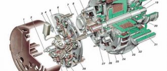
Design of rectifier modules
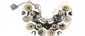
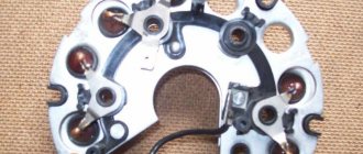
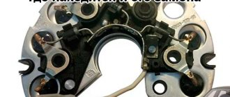
Structurally, diode bridges are made in the form of a removable rectifier module, which is mounted on the rear wall of the generator. The module uses power semiconductor diodes of various types and designs - it all depends on the characteristics of the generator. The module is based on two horseshoe-shaped aluminum plates (heat sinks), between which 6 or 8 power diodes and, if available, three additional diodes are installed in one way or another. The plates play the role of common wires (buses) for one row of power diodes (“positive” and “negative”). All electrical connectors for connecting to the stator windings and the voltage regulator are located here.
Diodes can have different designs - in the form of tablets, cylinders with leads, etc. These parts are sandwiched between the radiators or tightly inserted into holes drilled in the radiators. All electrical connections are made with large cross-section plates and wires. The assembled module is mounted on the generator using screws or other fasteners.
Why are there radiators in the rectifier module? The fact is that during operation of the generator, currents of tens of amperes pass through the diodes, which leads to heating of these devices. When heated, the characteristics of the diodes change, and at high temperatures their thermal breakdown can occur - the semiconductor device completely loses its properties. To prevent these consequences, diodes are installed on radiators to remove excess heat.
What you need to know about diode bridges
First, we will look at what they are and what is inside a diode bridge. These circuit elements are available in two versions:
- From discrete (separate) diodes. Usually soldered on the board and connected by tracks in the correct circuit.
- Diode assemblies. The assemblies can be either single-phase bridges for rectifying both half-cycles of alternating voltage, or assemblies of two diodes connected in a circuit by a common cathode or anode, and other connection options.
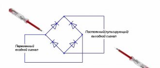
In any case, the rectifier single-phase diode bridge consists of four semiconductor diodes connected to each other in a series-parallel manner. Alternating voltage is supplied to two points at which the anode and cathode are connected (opposite poles of the diodes). Constant voltage is removed from the connection points of like poles: plus from the cathodes, minus from the anodes.
In the diagram, the connection point for alternating voltage is indicated by the symbols AC or “~”, and the outputs with constant voltage are “+” and “-“. Draw this diagram for yourself, it will be useful to us when checking.
If you imagine a real diode bridge and combine it with this circuit, you get something like:
Video: operating principle of a diode bridge
Causes of diode bridge failure and its symptoms
The diode bridge of the generator is structurally designed as a separate module. The forming elements may fail during ongoing operation. This happens for the following reasons:
- moisture entering the electrical circuit when washing a car or engine;
- penetration of dirt and oil into the generator housing with broken seals (occurs when driving at high speed on dirt roads);
- reversing the polarity of the battery contacts while “lighting” another car.
Indirect signs of bridge failure are manifested in the fact that
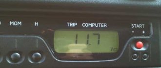
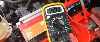
- the voltage at the generator output does not exceed 13.5 V or the ammeter needle is in the red sector;
- spark power decreases;
- the brightness of the headlights changes noticeably with changes in engine speed;
- the performance of the cooling system fan decreases;
- the starter does not develop the required number of revolutions;
- the normal functioning of the on-board air conditioning is disrupted.
We are looking for a diode bridge on the board
You can check both the diode bridge installed on the board and the one soldered from it; the second option is considered more accurate, since the test is not affected by other circuit elements, but it should be remembered that some testing methods can only be implemented in a working device. If the design of the device is quite complex or the board is overcrowded with parts, it is advisable to look for a diode bridge in the following locations:
- in power supplies;
- in secondary circuits of transformers;
- at the output of generators;
- in front of the batteries.
After detecting a diode bridge, it is necessary to inspect its housing or each diode individually. An experienced electrician will automatically notice the location of the inputs, but if it is difficult for you to focus on memory, you can draw a diagram in relation to your situation. On such a diagram you need to display the positive terminal and the negative terminal, the AC voltage input terminals.
It should also be noted that the malfunction may not only lie in the diode bridges, so during the inspection it is worth carefully inspecting all elements and parts, and when checking, do not exclude the integrity of the object.
Testing the diode bridge with a multimeter
Any part on the board can be desoldered for testing or ringing without desoldering. However, the accuracy of the check in this case is reduced, because perhaps a lack of contact with the board tracks, with visible “normal” soldering, the influence of other circuit elements. This also applies to the diode bridge; you don’t have to desolder it, but it’s better and more convenient to desolder it for testing. A bridge assembled from individual diodes is quite convenient to check on the board.
Almost every modern multimeter has a diode test mode, usually it is combined with an audio continuity test of the circuit.
This mode displays the voltage drop in millivolts between the probes. If the red probe is connected to the anode of the diode and the black probe to the cathode, this connection is called forward or conductive. In this case, the voltage drop across the PN junction of the silicon diode is in the range of 500-750 mV, which you can see in the picture. By the way, it shows a test in resistance measurement mode, this is also possible, but there is also a special diode test mode, the results will be, in principle, similar.
If you swap the probes - red to the cathode, and black to the anode, the screen will show either one or a value of more than 1000 (about 1500). Such measurements indicate that the diode is working; if the measurements differ in one of the directions, then the diode is faulty. For example, if the continuity test is triggered - the diode is broken, there are high values in both directions (as with reverse switching on) - the diode is broken.
Important!
Schottky diodes have a lower voltage drop, about 300 mV.
There is also an express check of the diode bridge with a multimeter. The procedure is as follows:
- We place probes at the input of the diode bridge (~ or AC), if the continuity test works, it is broken.
- We put the red probe on “–”, and the red one on “+” - a value of about 1000 appears on the screen, swap the probes - on the screen 1 or 0L, or another high value - the diode bridge is working. The logic of this test is that the diodes are connected in series in two branches, pay attention to the diagram, and they conduct current. If the positive power supply is applied to – (anode connection point), and the power supply minus is applied to “+” (cathode connection point), this is what happens during dialing. If one of the diodes is broken, current may flow through the other branch and you may make erroneous measurements. But if one of the diodes is broken, the voltage drop across one diode will be displayed on the screen.
The video below clearly shows how to check a diode bridge with a multimeter:
Checking the diode - how to do it right
Based on the fact that a diode is a semiconductor device that passes current only in one direction, let’s begin the test.
· The diode bridge must be removed. Diodes need to be checked individually, disconnected from the general circuit. The test must be performed in the “diode check” position.
· We touch the bottom of the diode with one of the probes, and its terminal with the other. The amount of resistance depends on the power of the semiconductor. The resistance should be in the range of 400 - 800 Ohms, that is, the diode passes current in this direction.
· Swap the probes. A unit on the multimeter screen is evidence that there is no conductivity in this direction. This means the diode is locked and intact.
· Otherwise, if the tester shows the presence of resistance (current flow) in both directions during testing, this indicates a diode malfunction.
Important to remember. When checking diodes located on the same plate, the resistance should not differ. The permissible maximum is 5 Ohms, no more. The presence of a diode with a large difference in readings indicates its poor performance and subsequent charging problems. Therefore, it is advisable to change the diode.
Checking diodes with a tester is very conditional; you can more accurately verify the integrity of the diode only under load, for example, by connecting a lamp to the circuit or on a diagnostic test bench at a service station.
Checking with an indicator screwdriver
This is the simplest test option, which will give a general idea of the condition of the diode bridge and the entire circuit as a whole. To operate, you only need an indicator; the entire procedure is performed under voltage, so extreme caution should be used:
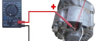
- Touch the tip of the screwdriver to each AC voltage terminal of the diode bridge in turn. If the light does not light, this indicates a fault in the circuit up to the diode bridge - a broken winding, a broken charger, etc. If the light is on, then voltage is supplied to the bridge normally.
Rice. 2. Testing with an indicator screwdriver
- Also touch the positive terminal with a screwdriver - if the light comes on, then the diode bridge normally passes positive half-cycles, respectively, there is potential at this pin. If it does not light, there is damage to the diode bridge.
- Repeat the same procedure with the negative terminal. Be sure to divide the test into both terminals of the rectifier unit, since a fault may be present in any diode and in any branch.
As you can see, in this example an insulated blade screwdriver was used. This is due to the need to perform work under voltage, when you can cover different parts of the electrical installation with a metal part, which will entail extremely unpleasant consequences. A significant disadvantage of the method is its low information content and the limitation on the operating voltage - since the indicator is designed for a nominal value of 220 V, it cannot be used for low-voltage circuits.
Video: Diode bridge. Examination
How to determine the health of the generator
Information about the operating status of the main unit responsible for generating electrical energy in the car is displayed on the dashboard for the convenience of motorists. The icon on the instrument panel that resembles a battery should go out after starting the vehicle’s power unit. This means that the power to the main electrical components has been switched from the battery to the generator. If the indicator does not go out, this indicates a breakdown in the electrical circuit. Problems may also be indicated by insufficient battery charge due to the lack of normal current rating.
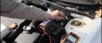
How to check without dismantling
You can diagnose the device on site without disassembling the generator or desoldering the part. To do this, unscrew all the wires on the generator and voltage regulator, set the tester to ohmmeter mode, and connect the lamp to the battery in the manner described above.
This method allows you to check the serviceability of the entire bridge and individual groups.
Short circuit
For this test, the positive electrode is applied to output 30 of the generator (“plus” of the power rectifier), and the negative electrode is applied to the housing. A resistance value of 1 indicates that the bridge is in good condition.
One end of the lamp is connected to the negative terminal of the generator, the other to the positive terminal. A lit lamp indicates a short circuit.
Negative group
The negative electrode of the tester is connected to the frame of the generator, the positive electrode is connected to one of the diode bridge mounting bolts. The negative group is operational if the resistance is infinity.
To check with a lamp, connect its minus to the generator casing, and the plus to the axle mounting bolt. The lamp lights up or flashes when there is a malfunction in the negative group of elements.
Positive
The positive probe of the multimeter is connected to the positive terminal, the negative one to the bridge mounting bolt. With a working group, the resistance is infinite.
The negative of the lamp is connected to the bridge mounting bolt, the plus is applied to the positive terminal. A lit lamp indicates a short circuit in the positive semiconductors.
Minor group
The positive electrode of the tester is pressed to terminal 61 (usually the “plus” of the additional rectifier), the negative electrode is connected to any bridge mounting bolt. The diodes are serviceable with a resistance value of 1.
The negative end of the lamp is connected to the bridge mounting bolt, and the positive end is connected to terminal 61. A lit lamp indicates a malfunction in this group.
Bridges can be made of individual diodes or made as a monolithic structure (diode assembly)
How to repair a diode bridge?
Before repairing the generator rectifier, preparation and a general check of the performance of the diodes should be carried out. The mechanism is checked in several stages:
- Disconnecting the voltage regulators and protective casing from the bridge.
- Check for short circuit using the battery and an incandescent lamp (in case of damage to the diodes, a short circuit occurs when an incandescent lamp is connected to the terminal of the battery and the generator housing).
- Checking the condition of positive and negative elements (by connecting the plus and minus terminals of the battery and generator).
- Checking the diode bridge circuit.
- Repair or replacement of non-working elements.
Since the generator diode bridge has a low cost, every car enthusiast can repair the equipment. However, manual repairs will take a lot of time, and in order not to waste extra hours searching for information on the Internet, we suggest drivers adhere to the following recommendations:
- During the repair process, you will still have to remove the diode bridge assembly.
- The constant ingress of water into the unit causes its increased wear resistance, so it is advisable to move the rectifier to another place - less susceptible to moisture ingress. Experienced experts advise protecting the on-board network with a reliable housing under the hood.
- Pressing and unpressing the rectifier yourself will be more expensive than at a service station, but the car owner will be confident in its reliability.
- Buying diodes on the spontaneous market will be cheaper, but there is a risk of parts malfunctioning.
- Before replacing the rectifier, it is necessary to remove the insulator and the old fastener element, and be sure to transfer them to the new diode bridge.
If you want to upgrade the rectifier and install three levels of a generator relay, buy three more pairs of diode bridges that will create an independent “plus”.
Important! Checking the serviceability of parts purchased on the market is quite simple: if the “ringing” of the diode in a cold state shows from 500 to 800 Ohms, and when the engine starts, a thermal “breakdown” occurs, the design is faulty.
Useful tips
As practice shows, the diode bridge of the generator often burns out precisely as a result of the carelessness of the car owner himself. If there is an incorrect connection of the battery terminals, the load on the generator is prohibitively high, then the diodes burn quickly.
It is also important to understand that active use of the car, as a result of which dirt and water gets on the generator, does not add resource to the diode bridge. As a result, in order to increase service life, you need to properly wash the engine, follow the rules for connecting terminals to the battery, know how to light a car, etc.
We also recommend reading the article on how to quickly check the functionality of the generator. From this article you will learn what signs indicate that the generator is faulty, as well as how to check the generator with a multimeter without removing it.
In the case where there is no new diode bridge, then the solution is to replace the failed individual elements. To replace, you need a powerful soldering iron, as well as known-good diodes in stock.
Please note that replacing the entire diode bridge at once is also not always advisable. If the generator has been in service for a long time, then it is optimal to change the diode bridge assembly, but this will be a more expensive solution.
In cases where the generator is not old, and the breakdown occurred due to an accidental mistake by the owner (for example, after lighting the car), you can limit yourself to only repairing the generator. Often, in this case, there is no need to fear that other diodes will also begin to burn out quickly (provided that the rules are followed during further operation).
How is the replacement performed?
Let's say checking the diode bridge shows that there is a problem. It is necessary to disconnect all wires from the generator, remove and disassemble the device. In some models, the part is attached directly to the unit with bolts, but there are devices in which the housing must be removed to access the rectifier.
Next, as part of the repair, faulty diodes are replaced - if this is economically feasible and it is difficult to find the required generator model on sale. Or they change the component entirely. Upon completion of work on the stand, the serviceability of the component and the electrical system as a whole is checked using a multimeter, and the part is assembled and installed on the car.
You can check the diode bridge yourself if you have the time and skills to disassemble the generator. But even after checking and detecting faulty diodes, you will need to select and correctly install a new element instead of the faulty one. Remember that a faulty generator can cause failure of expensive electrical equipment, short circuits and spontaneous combustion of the car. Therefore, it is better to trust repairs and diagnostics to car service technicians, who will definitely be able to call you correctly!
What causes the need to replace diodes
Someone will say that it is much easier to take and replace the diode bridge completely. However, the cost of a diode bridge for a foreign car varies from 1000 to 4000 rubles, sometimes the price is even higher. Depends on the brand of the car, the type of generator, whether it is an analogue or an original. New diode bridge or under contract. You ordered a diode bridge online, you thought it was new and original, but an unscrupulous storekeeper put a Chinese equivalent in your package. Go figure it out right away.
Many, having replaced the diode bridge on their generator, prefer not to throw away the old one, but to repair it and leave it in their stash.