The working cycle of an internal combustion engine is a periodically repeating series of sequential processes occurring in each working cylinder. The main task of the work process is to convert thermal energy from the combustion of the working fluid into mechanical work, in particular into the rotational movement of the crankshaft. Car engines most often operate on a four-stroke cycle, which is completed in two revolutions of the crankshaft or four strokes of the piston and consists of intake, compression, expansion and exhaust strokes.
In a carburetor four-stroke engine, the operating cycle occurs as follows.
The first stroke is intake.
The structure of a modern engine
|
The piston moves from TDC to BDC, and purified air enters the cylinder through the open intake valve (due to the vacuum created by the piston). The air is mixed with a small amount of exhaust gases remaining from the previous cycle, the temperature rises and at the end of the intake stroke reaches 300-320 K, and the pressure 0.08-0.09 MPa. The cylinder filling coefficient is 0.9 or higher, i.e. more than that of a carburetor engine.
Marine internal combustion engines (SICE)
Diesel engine is a piston internal combustion engine operating on the principle of self-ignition of atomized fuel
IA Neftegaz.RU.
The first marine internal combustion engines (ICEs) appeared at the beginning of the 20th century. The Danish ship Zealand, built in 1912, had a diesel installation with 2 diesel engines with a power of 147.2 kW each.
Currently, the bulk of the main power plants installed on ships are internal combustion engines.
Only ships with engine power from 14,700 to 22,100 kW have steam turbine installations.
A diesel power plant consists of one or more main engines, as well as the mechanisms that serve them.
Depending on the method of implementing the working cycle, internal combustion engines are divided into 4-stroke and 2-stroke.
An additional increase in power is achieved through supercharging.
According to the rotation speed, internal combustion engines are divided into: low-speed diesel engines with a rotation speed of 100-150 rpm, which directly drive the ship propulsion system; medium speed - 300-600 rpm, which drive the ship's propulsor through a gearbox.
Until the end of the 60s, reversible main engines were installed on ships, allowing the ship to reverse. Only at low power, special devices (reversing gearboxes) were used to reverse the internal combustion engine, allowing maneuvering.
In the 60s, simultaneously with the advent of adjustable pitch propellers, non-reversible internal combustion engines began to be used as the main engine, first on small ships, trawlers and tugs, and then on large merchant ships. Due to this, the design of the engines has been simplified.
The third stroke is the working stroke.
At the end of the compression stroke (20-30 degrees of rotation angle of the crankshaft before the piston reaches TDC), a portion of fuel is injected in a finely atomized form through a nozzle into the cylinder under high pressure (15-20 MPa) using a pump. Fuel evaporates when it comes into contact with heated air, its vapors mix with the heated air and ignite. When fuel burns, due to the supply of a large amount of heat, the depletion and temperature of the resulting gases sharply increase. At the beginning of the expansion stroke, the gas pressure is 7-8 MPa. and the temperature is 2100-2300 K. Under the influence of pressure, the piston moves from TDC to BDC, performing useful work. The volume of the cylinder increases, the pressure and temperature of the gases decrease and when the piston approaches BDC they are 0.2-0.4 MPa.
Turbofan engine
A turbofan engine is something of a compromise between a turbojet and a turboprop. It works like a turbojet, but there is one peculiarity: the turbine shaft rotates an external fan, which has more blades and spins faster than the propeller. This helps this engine remain efficient at high altitudes where the air is thin.
Sources: www.animatedengines.com
- Ultimate Visual Dictionary, DK Publishing Inc., 1999
- Building the Atkinson Cycle Engine, Vincent Gingery, David J Gingery Publishing, 1996
- The Stirling Engine Manual, James G. Rizzo, Camden Miniature Steam Services, 1995
- Modern Locomotive Construction, J. G. A. Meyer, 1892, reprinted by Lindsay Publications Inc., 1994
- Five Hundred and Seven Mechanical Movements, Henry T. Brown, 1896, reprinted by The Astragal Press, 1995
- Model Machines/Replica Steam Models, Marlyn Hadley, Model Machine Co., 1999
- Air Board Technical Notes, RAF Air Board, 1917, reprinted by Camden Miniature Steam Services, 1997
- Internal Fire, Lyle Cummins, Carnot Press, 1976
- Toyota Web site Prius specifications
- Steam and Stirling Engines you can build, book 2, various authors, Village Press, 1994
- Knight's New American Mechanical Dictionary, Supplement Edward H. Knight, A.M., LL. D., Houghton, Mifflin and Company, 1884
- Thomas Newcomen, The Prehistory of the Steam Engine LTC Rolt, David and Charles Limited, 1963
- An Introduction to Low Temperature Differential Stirling Engines James R. Senft, Moriya Press, 1996
- An Introduction to Stirling Engines James R. Senft, Moriya Press, 1993
UPD:
I added Wankel and CO2 engines, they seemed to me the most interesting and practically useful.
UPD2:
Added a description of a whole family of jet engines: rocket, turbojet, turboprop, turbofan.
The fourth measure is release.
The piston moves from BDC to TDC. Through the open exhaust valve, the exhaust gases are pushed out through the exhaust pipe into the environment. At the end of the exhaust stroke, the gas pressure is 0.11 -0.12 MPa, the temperature is 850-1200. After this, the diesel operating cycle is repeated. In two-stroke engines, the time allotted for the working cycle is used more fully, since the exhaust and intake processes are combined in time with the compression and power stroke processes. The operating cycle occurs over 360 degrees (one revolution of the crankshaft).
When the piston moves from TDC to BDC, expansion and exhaust processes occur simultaneously with purging of the cylinder, and when the piston moves back from BDC to BDC, intake and compression occur. Changes in cycle parameters (pressure and temperature) correspond to changes in four-stroke engine parameters. A comparison of the operating cycles of four- and two-stroke engines shows that with the same cylinder dimensions and crankshaft rotation speed, the power of two-stroke engines is 1.5–1.7 times higher. It is simpler in design and more compact. The disadvantages of a two-stroke engine include the limited gas exchange time, which impairs the cleaning of the cylinder from exhaust gases, increases the loss of part of the fresh charge, and reduces efficiency.
Diesel engine operation, more details
Duty cycle of a four-stroke carburetor engine
Internal combustion engines differ from each other in the duty cycle in which they operate.
The work cycle is a set of sequential work processes that are periodically repeated in each cylinder during engine operation.
The working process occurring in the cylinder during one stroke of the piston is called a stroke.
Based on the number of cycles that make up the operating cycle, engines are divided into two types:
– four-stroke, in which the working cycle is completed in four piston strokes,
– two-stroke, in which the working cycle is completed in two strokes of the piston.
Passenger cars typically use four-stroke engines, while motorcycles and motorboats two-stroke engines. We’ll talk about traveling across expanses of water sometime later, but we’ll deal with the four strokes of a car engine now.
The operating cycle of a four-stroke carburetor engine consists of the following strokes:
– inlet of the combustible mixture,
– compression of the working mixture,
– working stroke,
– exhaust gas release.
Rice. 8. Operating cycle of a four-stroke carburetor engine: a) intake; b) compression; c) working stroke; d) release
The first stroke is the intake of the combustible mixture (Fig. 8 a
).
A combustible mixture is a mixture of finely atomized gasoline and air in a certain proportion. The carburetor or injector prepares the mixture in the engine, which we will talk about a little later. In the meantime, you should know that a gasoline to air ratio of approximately 1:15 is considered optimal to ensure a normal combustion process.
During the intake stroke, the piston moves from top dead center to bottom dead center. The volume above the piston increases. The cylinder is filled with a combustible mixture through an open inlet valve. In other words, the piston sucks in the combustible mixture.
The mixture continues to be injected until the piston reaches bottom dead center. During the first stroke of engine operation, the crankshaft crank rotates half a turn.
During the process of filling the cylinder, the combustible mixture is mixed with the remaining exhaust gases and changes its name; now this mixture is called the working mixture.
The second stroke is compression of the working mixture (Fig. 8 b
)
.
During the compression stroke, the piston moves from bottom dead center to top dead center. Both valves are tightly closed, so the working mixture is compressed.
Everyone knows from school physics that when gases are compressed, their temperature increases. The pressure in the cylinder above the piston at the end of the compression stroke reaches 9–10 kg/cm², and the temperature is 300–400°C.
In the factory instructions for the car, you can see one of the engine parameters with the name “compression ratio” (for example, 8.5). And what is it?
The compression ratio shows how many times the total volume of the cylinder is greater than the volume of the combustion chamber ( Vn/Vc - see Fig. 7). In gasoline engines, at the end of the compression stroke, the volume above the piston decreases by 8–11 times.
During the compression stroke, the engine crankshaft rotates another half-turn. From the beginning of the first beat to the end of the second, it will turn one turn.
The third stroke is the power stroke (Fig. 8c
)
.
During the third stroke, the energy released during combustion of the working mixture is converted into mechanical work. The pressure from the expanding gases is transmitted to the piston and then, through the connecting rod and crank, to the crankshaft.
This is where the force comes from that makes the engine crankshaft and, ultimately, the drive wheels of the car rotate.
At the very end of the compression stroke, the working mixture is ignited by an electric spark that jumps between the electrodes of the spark plug. At the beginning of the power stroke, the burning mixture begins to actively expand. Since the intake and exhaust valves are still closed, the expanding gases have only one way out - to press on the movable piston.
Under the influence of pressure reaching 50 kg/cm², the piston begins to move to the bottom dead center. At the same time, a force of several tons presses on the entire area of the piston, which is transmitted through the connecting rod to the crankshaft crank, creating torque.
During the power stroke, the temperature in the cylinder reaches more than 2000 degrees.
During the working stroke, the crankshaft makes regular half turns.
The fourth stroke is the release of exhaust gases (Fig. 8 d
).
As the piston moves from bottom dead center to top dead center, the exhaust valve opens (the intake valve is still closed), and the exhaust gases are expelled from the engine cylinder at great speed.
This is why you hear that loud rumble when a car drives down the road without a muffler, but more on that later. In the meantime, let's pay attention to the engine crankshaft - during the exhaust stroke it makes another half a revolution. And in just four strokes of the working cycle, he made two full revolutions.
After the exhaust stroke, a new working cycle begins, and everything is repeated: intake - compression - power stroke - exhaust... and so on.
Now, I wonder how many of you have noticed that useful mechanical work is performed by a single-cylinder engine only during one stroke - the power stroke! The remaining three strokes (exhaust, intake and compression) are only preparatory and they are performed due to the kinetic energy of the crankshaft and flywheel rotating by inertia.
The flywheel (Fig. 9) is a massive metal disk that is mounted on the engine crankshaft. During the power stroke, the piston spins the engine crankshaft through the connecting rod and crank, which transfers a reserve of rotational energy to the flywheel.
Rice. 9. Engine crankshaft with flywheel: 1 – connecting rod journal; 2 – counterweight; 3 – flywheel with toothed ring; 4 – root (supporting) neck; 5 – engine crankshaft
The rotational energy stored in the mass of the flywheel allows it to carry out the preparatory strokes of the engine operating cycle in reverse order through the crankshaft, connecting rod and piston. The piston moves up (during the exhaust and compression strokes) and down (during the intake stroke) precisely due to the energy given off by the flywheel.
If an engine has several cylinders operating in a certain order, then the preparatory strokes in some cylinders are performed due to the energy developed in others, and the flywheel, of course, also helps.
As a child, you probably had a toy called a top. You spun it with the energy of your hand
(
working stroke
)
and joyfully watched how long it rotated.
The engine's massive flywheel is exactly the same - once it spins, it stores energy, but only much more than a child's toy, and then this energy is used to move the piston in the preparatory strokes. Internal combustion engines differ from each other in the duty cycle in which they operate.
The work cycle is a set of sequential work processes that are periodically repeated in each cylinder during engine operation.
The working process occurring in the cylinder during one stroke of the piston is called a stroke.
Based on the number of cycles that make up the operating cycle, engines are divided into two types:
– four-stroke, in which the working cycle is completed in four piston strokes,
– two-stroke, in which the working cycle is completed in two strokes of the piston.
Passenger cars typically use four-stroke engines, while motorcycles and motorboats two-stroke engines. We’ll talk about traveling across expanses of water sometime later, but we’ll deal with the four strokes of a car engine now.
The operating cycle of a four-stroke carburetor engine consists of the following strokes:
– inlet of the combustible mixture,
– compression of the working mixture,
– working stroke,
– exhaust gas release.
Rice. 8. Operating cycle of a four-stroke carburetor engine: a) intake; b) compression; c) working stroke; d) release
The first stroke is the intake of the combustible mixture (Fig. 8 a
).
A combustible mixture is a mixture of finely atomized gasoline and air in a certain proportion. The carburetor or injector prepares the mixture in the engine, which we will talk about a little later. In the meantime, you should know that a gasoline to air ratio of approximately 1:15 is considered optimal to ensure a normal combustion process.
During the intake stroke, the piston moves from top dead center to bottom dead center. The volume above the piston increases. The cylinder is filled with a combustible mixture through an open inlet valve. In other words, the piston sucks in the combustible mixture.
The mixture continues to be injected until the piston reaches bottom dead center. During the first stroke of engine operation, the crankshaft crank rotates half a turn.
During the process of filling the cylinder, the combustible mixture is mixed with the remaining exhaust gases and changes its name; now this mixture is called the working mixture.
The second stroke is compression of the working mixture (Fig. 8 b
)
.
During the compression stroke, the piston moves from bottom dead center to top dead center. Both valves are tightly closed, so the working mixture is compressed.
Everyone knows from school physics that when gases are compressed, their temperature increases. The pressure in the cylinder above the piston at the end of the compression stroke reaches 9–10 kg/cm², and the temperature is 300–400°C.
In the factory instructions for the car, you can see one of the engine parameters with the name “compression ratio” (for example, 8.5). And what is it?
The compression ratio shows how many times the total volume of the cylinder is greater than the volume of the combustion chamber ( Vn/Vc - see Fig. 7). In gasoline engines, at the end of the compression stroke, the volume above the piston decreases by 8–11 times.
During the compression stroke, the engine crankshaft rotates another half-turn. From the beginning of the first beat to the end of the second, it will turn one turn.
The third stroke is the power stroke (Fig. 8c
)
.
During the third stroke, the energy released during combustion of the working mixture is converted into mechanical work. The pressure from the expanding gases is transmitted to the piston and then, through the connecting rod and crank, to the crankshaft.
This is where the force comes from that makes the engine crankshaft and, ultimately, the drive wheels of the car rotate.
At the very end of the compression stroke, the working mixture is ignited by an electric spark that jumps between the electrodes of the spark plug. At the beginning of the power stroke, the burning mixture begins to actively expand. Since the intake and exhaust valves are still closed, the expanding gases have only one way out - to press on the movable piston.
Under the influence of pressure reaching 50 kg/cm², the piston begins to move to the bottom dead center. At the same time, a force of several tons presses on the entire area of the piston, which is transmitted through the connecting rod to the crankshaft crank, creating torque.
During the power stroke, the temperature in the cylinder reaches more than 2000 degrees.
During the working stroke, the crankshaft makes regular half turns.
The fourth stroke is the release of exhaust gases (Fig. 8 d
).
As the piston moves from bottom dead center to top dead center, the exhaust valve opens (the intake valve is still closed), and the exhaust gases are expelled from the engine cylinder at great speed.
This is why you hear that loud rumble when a car drives down the road without a muffler, but more on that later. In the meantime, let's pay attention to the engine crankshaft - during the exhaust stroke it makes another half a revolution. And in just four strokes of the working cycle, he made two full revolutions.
After the exhaust stroke, a new working cycle begins, and everything is repeated: intake - compression - power stroke - exhaust... and so on.
Now, I wonder how many of you have noticed that useful mechanical work is performed by a single-cylinder engine only during one stroke - the power stroke! The remaining three strokes (exhaust, intake and compression) are only preparatory and they are performed due to the kinetic energy of the crankshaft and flywheel rotating by inertia.
The flywheel (Fig. 9) is a massive metal disk that is mounted on the engine crankshaft. During the power stroke, the piston spins the engine crankshaft through the connecting rod and crank, which transfers a reserve of rotational energy to the flywheel.
Rice. 9. Engine crankshaft with flywheel: 1 – connecting rod journal; 2 – counterweight; 3 – flywheel with toothed ring; 4 – root (supporting) neck; 5 – engine crankshaft
The rotational energy stored in the mass of the flywheel allows it to carry out the preparatory strokes of the engine operating cycle in reverse order through the crankshaft, connecting rod and piston. The piston moves up (during the exhaust and compression strokes) and down (during the intake stroke) precisely due to the energy given off by the flywheel.
If an engine has several cylinders operating in a certain order, then the preparatory strokes in some cylinders are performed due to the energy developed in others, and the flywheel, of course, also helps.
As a child, you probably had a toy called a top. You spun it with the energy of your hand
(
working stroke
)
and joyfully watched how long it rotated. The engine's massive flywheel is exactly the same - once it spins, it stores energy, but only much more than a child's toy, and then this energy is used to move the piston in the preparatory strokes.
Unit design
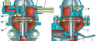
The camshaft of a four-stroke engine is located in the cylinder cover. It is driven by a drive wheel mounted in the crankshaft. The camshaft opens and closes one of the valves: exhaust or intake, depending on the location of the piston. The camshaft also contains cams that operate the valve rocker arms.
Once triggered, the rocker arms It is important that there must be a thermal gap (narrow gap) between the adjusting screw and the valve. When heated, the metal expands, so if the gap is too small or there is none at all, the valves cannot completely close the exhaust and intake passages.
at the intake valve should be smaller than at the exhaust valve, because the exhaust gases are hotter than the mixture. Accordingly, the intake valve heats up less than the exhaust valves.
In a four-stroke diesel engine, working processes occur as follows.
The piston moves from BDC to TDC. The intake and exhaust valves are closed, as a result of which the upward moving piston compresses the air present in the cylinder. For fuel to ignite, the temperature of the compressed air must be higher than the auto-ignition temperature of the fuel.
— Expansion stroke, or power stroke As the piston approaches TDC, diesel fuel is injected into the cylinder through an injector, supplied by a high-pressure fuel pump (HPF). The injected fuel, mixing with heated air, self-ignites and the combustion process begins, characterized by a rapid increase in temperature and pressure. Under the influence of gas pressure, the piston moves from TDC to BDC. A working process is taking place.
— Exhaust stroke The piston moves from BDC to TDC and through the open exhaust valve the exhaust gases are pushed out of the cylinder. After the end of the exhaust stroke, with further rotation of the crankshaft, the working cycle is repeated in the same sequence.
This video shows the operation of a real engine. The camera is built into the cylinder of the block.
Car design for dummies
Each pin has two connecting rods: on the first one - the connecting rod of the first and fourth cylinders, on the second - the second and fifth, on the third - the third and sixth cylinders. The crank mechanisms of V-shaped four-stroke engines and their operating diagrams are shown in Figure 3.
The order of operation of the cylinders in such an engine is 1-4-2-5-3-6.
In these engines it is impossible to achieve uniform alternation of cylinder strokes. They pass through 90˚ and 150˚.
If the first cylinder moves, the fourth cylinder starts at an angle of 90°, the second cylinder at an angle of 150°, the fifth at 90°, and the sixth at 150°, which is a significant drawback of this design solution for the arrangement of cylinders in a six-cylinder engine.
Operating principle and main characteristics
The operating cycle of an internal combustion engine (ICE) consists of a series of processes that increase the power of the engine acting on the crankshaft. The work cycle consists of several stages:
In an internal combustion engine, the piston moves in one direction (up or down). The crankshaft makes one revolution in two strokes. The working stroke of the piston is the one during which useful work is performed and the burnt gases expand.
Two-stroke engines are those in which the cycle is completed in one revolution of the crankshaft or in two strokes. Four-stroke units are characterized by completing a working cycle in two revolutions of the crankshaft or in four strokes .
Main characteristic indicators of a 4-stroke engine:
Story
Around 1854-1857, the Italians Felicce Matoczi and Eugene Barsanti created a device that, according to the information available today, was similar to a four-stroke engine . The invention of the Italians was lost only in 1861. Alphon de Rocher patented an engine of this type.
The first workable four-stroke engine was created by the German engineer Nikolaus Otto . The four-stroke cycle of operation was named in his honor as the Otto cycle, and a 4-stroke engine using spark plugs is called an Otto engine.
Features of a 4-stroke engine
In a two-stroke engine, lubrication of the piston and cylinder pins, crankshaft, piston, bearing and compressor rings is carried out by pouring oil into gasoline. The crankshaft of a 4-stroke engine is located in an oil bath, which is a significant difference. That is why there is no need to mix fuel and add oil. All the car owner needs to do is fill the fuel tank with gasoline.
The car owner, therefore, has no need to purchase special oil, without which a two-stroke engine cannot function. In addition, with a four-stroke engine, the amount of carbon deposits on the piston mirror and on the walls of the muffler is reduced. Another important difference is that in a two-stroke engine, a flammable mixture splashes into the exhaust pipe, which is due to its design.
It should be recognized that four-stroke engines also have minor disadvantages. For example, their working moments for regulating the thermal valve clearance are not particularly high-quality.