It so happened that in order to install the dashboard from the GAZ 3110 in my beloved VAZ 2105 (with a torpedo and wiring from the 2107), I needed a pinout of the instrument cluster from the VAZ 2107. To my great surprise and horror, a search in Google and Yandex did not give a single clear result , the information is fragmentary everywhere and not always correct, so I decided to put everything together and write a small post-instruction for myself, in case it’s useful to someone else
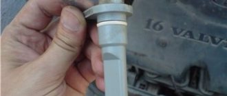
In fact, the confusion arises due to the fact that there are at least 2 most popular types of these devices: the old type with an oil pressure indicator, and the newer one with an econometric indicator. In general, to find out which one you have, look at the upper left device: if an oil can is drawn there, it means you have an older one, and if it says ECON, it means a new one. By the way, in my photo there is a tidy device with an econometer (you can see its piping sticking out on the right).
Pinout of the old instrument cluster (with oil pressure indicator)
In addition to the presence of an oil pressure indicator, it is worth noting that this instrument panel does not have an air damper indicator lamp (choke), and the emergency oil pressure lamp is located next to the pressure indicator. Because of this, it contains lamps for low brake fluid levels and fog lamps.
White 6-terminal block X1:
- Gasoline level sensor
- Turn signal indicator lamp
- Battery charge sensor (voltmeter -)
- Gasoline level warning lamp
- Overall plus (+)
- Battery charge sensor (voltmeter +)
White 8 terminal block X2:
- Fog lamp warning lamp
- High beam warning lamp
- Dimensions indicator lamp
- Empty
- Battery charge indicator lamp
- Brake fluid level warning lamp
- Empty
- Parking brake warning lamp (handbrake)
Orange 6-terminal block X3:
- General minus (-)
- Tachometer
- Instrument lighting
- Oil pressure sensor
- Oil pressure warning lamp
- Coolant temperature sensor
Pinout of the dashboard of VAZ2110, 2111, 2112
- fuel reserve warning lamp;
- dashboard lighting lamps;
- right repeater indicator lamp;
- left repeater indicator lamp;
- VAZ plug block;
- coolant temperature sensor;
- indicator lamp for external lighting;
- carburetor air damper warning lamp;
- oil pressure warning lamp;
- handbrake indicator lamp;
- battery charge indicator lamp;
- VAZ tachometer;
- indicator light “CHECK ENGINE”;
- speedometer dashboard;
- brake fluid level warning lamp;
- hazard warning lamp;
- high beam indicator lamp;
- fuel level indicator.
Pinout of the new instrument cluster (with econometer)
Here, everything is the other way around - there is no oil pressure indicator (instead there is an econometer), instead of a brake fluid level lamp there is a suction lamp (or an engine management system lamp on injectors), and instead of a fog lamp lamp there is an oil pressure lamp.
White 6-terminal block X1:
- Gasoline level sensor
- Turn signal indicator lamp
- Battery charge sensor (voltmeter -)
- Gasoline level warning lamp
- Overall plus (+)
- Battery charge sensor (voltmeter +)
White 8 terminal block X2:
- Dimensions indicator lamp
- High beam warning lamp
- Oil pressure warning lamp
- My dash is empty, but there is a terminal in the wiring that goes to the brake fluid level sensor
- Battery charge indicator lamp
- Indicator lamp for the air damper (choke) or engine control unit for injectors
- Empty
- Parking brake warning lamp (handbrake)
Orange 6-terminal block X3:
I decided not to list the colors of the wires here, so as not to completely confuse anyone, because the colors are generally different in all circuits. If you have any questions, I will be happy to help!
Repairing auto parts yourself is a responsible task that should be taken as seriously as possible. Sometimes a faulty spare part takes the driver by surprise, forcing him to spend a lot of time and money searching for a good service station, but there is an alternative solution to the problem; this requires a small amount of knowledge and a set of tools.
When repairing the connection diagram of the VAZ 2105 Zhiguli instrument cluster, you need to be extremely careful and not neglect the little things. To get acquainted with the issue, car enthusiasts often use various Internet portals dedicated to auto parts. Some of them use narrowly focused forums. But, as a rule, only generalized information is provided there, which is known initially. Where can you find a reliable source that offers really useful things? Our portal is open for this 24 hours a day. Online mode allows us to help clients at any time convenient for them. Moreover, a mobile version has been developed that is available to everyone.
A detailed description of such a unit as the connection diagram of the VAZ 2105 Zhiguli instrument cluster has a good structure with thematic headings. In addition, there is always the opportunity to familiarize yourself with the intricacies of installation. There are often situations when a driver is confident in his abilities, but when he gets down to work, questions begin to arise. Thanks to our portal, such moments can be easily avoided. The site is a database that is updated regularly. By using it as a support during repair work, the car enthusiast receives a serious advantage. Each of the articles has reliable support, tested in practice.
In addition to the repair manual, the owner of a personal car will be able to prevent a lot of breakdowns that occur due to the human factor, thanks to the information located on the site. Users are presented with a lot of useful recommendations for proper operation, which will help significantly extend the life of the unit and avoid many negative consequences.
Online support is an excellent and most convenient way to obtain the necessary information. Another significant plus is that articles are written for people. We understand that the reader will do everything with his own hands, and we try to make it as convenient and efficient as possible. Use the resource at any time of the day and find the answer to any question you may have regarding cars.
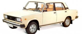
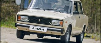
The VAZ 2105 model first appeared on city streets in 1980 and immediately became extremely popular. The fact is that the design of the car repeated the features of European models of those years: front and rear headlights, aluminum bumpers, and a modern instrument panel.
All this required the designers to rework the usual electrical circuit of the car.
The original diagram published in the article will make it easier for car owners and service station technicians to find faults in the electrical system of a Zhiguli family car.
The VAZ 2105 wiring diagram together with a verification tester will allow you to:
- determine the causes of circuit failure;
- identify which sensor or relay has stopped performing its functions;
- establish a breakdown in the ignition system;
- identify the circuit whose fuse has blown;
- check the on-board voltage supplied by the generator;
- find the cause of failure of incandescent lamps, etc.
Historical reference
The VAZ 2101 platform was taken as the basis for production. At its core, it was the same rear-wheel drive five-seater sedan car. The VAZ 2105, with its design, practically copied the models of cars produced in Europe in the early 80s, and cost an order of magnitude lower, which predetermined its popularity in Western countries.
Abroad, the car was named Lada Riva and Lada Nova (depending on the country of sale). Under these names he was shown in video advertisements.
The car plant produced several modifications of the VAZ 2105:
- With the VAZ-2105 index, the car was equipped with a 4-speed gearbox. gearbox and 1290 cc carburetor engine. cm (63 hp);
- The VAZ-21050 was equipped with a 5-speed checkpoint;
- The VAZ-21051 was equipped with an engine from the VAZ 2101 (volume 1200 cc, power 58 hp) with a 4-speed. checkpoint;
- The VAZ-21053 was equipped with a VAZ-2103 carburetor engine (volume 1450 cc, power 71 hp);
- The VAZ-21053-20 was equipped with an injection engine from the VAZ-2104 (volume 1450 cc, power 71 hp), which met Euro-2 requirements. It also came with 5 tbsp. Transmission.
For reference: the electrical wiring of the VAZ 21053 was distinguished by a different form of terminals in the engine compartment. This was caused by the installation of an ECM - an electronic engine management system and additional sensors.
VAZ 2105 models
- VAZ 2105 is a small passenger car with a monocoque 4-door sedan-type body. Engine of the VAZ 2105 model with a displacement of 1.3 liters and a power of 63.6 hp. Has a maximum speed of 145 km/h;
- VAZ 21051 - differs from the VAZ 2105 car in the engine of the VAZ 2101 model with a power of 58.7 hp and a displacement of 1.2 liters. The car has a top speed of 142 km/h;
- VAZ 21053 - differs from the base model VAZ 2105 in the engine, which has a displacement of 1.5 liters. The car has a maximum speed according to its passport of 150 km/h. The car is equipped with a VAZ 2103 engine with a power of 70.2 hp.
Features of the electrical equipment of the VAZ 2105 car
The electrical equipment of the VAZ-2105 car is made according to the classic single-wire circuit for the Zhiguli family, in which:
- the metal body of the car plays the role of a second wire;
- the negative terminals of all electrical devices and components are connected to ground;
- electrical circuits are protected by fuses;
- the operation of the main systems is activated through the vehicle's ignition switch.
For reference: the ignition switch controls electrical networks by supplying power from the battery or generator. The contact group of the lock is designed in such a way that when the engine starts, the electrical wiring of the VAZ 2105 secondary circuits is turned off.
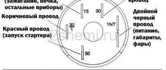
Egnition lock
The ignition switch was used as a control system for the vehicle's electrical systems, which had four main positions:
For reference: the factory instructions inform you that, regardless of the position of the key, the interior lighting lamps, brake light lamps (when the brake pedal is pressed), the horn and the connector for connecting a portable lamp remain energized.
Fuse and relay box
To protect electrical circuits and devices, a fuse circuit is used to break the electrical connection. This happens when the voltage increases - the fuse-link melts due to temperature and the circuit is disconnected.
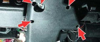
The photo shows:
- From 1 to 17 – fuses;
- Relay 18 is responsible for turning on the low beam headlights;
- Relay 19 is responsible for turning on the high beam headlights;
- Relay 21 activates the headlight cleaner and washer;
- Relay 22 is responsible for turning on the heated rear window.
For reference: under No. 20 the jumper is indicated. The wiring diagram of the VAZ 21053 in the export version is distinguished by the installation of a relay for turning on sound signals in this place.
Headlight unit
The main and most noticeable difference from the classic Zhiguli models of the VAZ 2105 were the headlights. It was their massive appearance that gave the car a modern look. And the ability to remotely adjust the direction of the light beam was completely new.
For these purposes, several main and additional devices were used, among which a new product was the hydraulic headlight corrector.
His role was as follows:
- When the car was loaded, the rear part of the body lowered;
- The luminous flux of high and low beam headlights began to blind oncoming vehicles;
- With the help of a hydraulic corrector, the driver could lower (tilt) the headlights without leaving the car.
Thanks to this, the problem of driving safety in the dark was solved.
Electrical part of the VAZ 2105: how to understand the interweaving of wires?
The electrical circuit of VAZ cars, in principle, is not particularly complicated, but some faults can simply confuse the car owner. In this article we will talk about the VAZ 2105 car - a schematic diagram of the electrical equipment, as well as recommendations for repairing the system are also given below.
The VAZ electrical circuit consists of many components. We are talking about the generator, battery, optics, fuse blocks, warning lamps, as well as the instrument panel and other components.
We are talking about both injector and carburetor engines.
The system wires are marked in different colors, they correspond to those marked on the diagrams, this allows the car owner not to get confused during circuit diagnostics and repairs.
Complete wiring diagram for the domestic “five”
The wiring diagram of a VAZ 21053 carburetor or injector as a whole gives a complete picture of the circuit, without any specifics or explanations.
Accordingly, the service manual for the vehicle should contain additional appendices explaining the purpose of electrical devices. In any case, one of the main components of the circuit is the ignition system.
In general, there is nothing complicated about it, but during repairs it is easy to get confused in the wiring that goes from the relay to the fuse block and from the ignition switch to the block.
The wiring system also includes the electrical circuit for the instrument panel and engine start. Almost all equipment of the “five” is indicated by separate applications in the service manual, which greatly facilitates the repair and diagnostic procedure. For example, car owners often face the problem of direction indicators and fog lights not working correctly.
It is quite possible that devices refuse to function normally if the generator is not working correctly. Of course, if you have a diagram, it will be much easier to detect a malfunction. It should be noted that injection versions, unlike carburetor versions, are more complex due to the presence of additional sensors and regulators, injectors and other components.
Signs of trouble
There are several types of condition of the “five” electrical circuit when car owners have to look for a malfunction:
- The car can't move. In principle, there can be many reasons for this. This could be a breakdown of certain components and mechanisms, or problems in the operation of the electrical circuit.
- The car can be driven, but the electrical equipment is not functioning correctly.
Description and location of indicators and instruments on the panel
In order to fully use the information that the dashboard provides, you need to know the location and purpose of its instruments and indicators, and their characteristics. The instruction manual provides a description of the device. A standard panel consists of a set of measuring and control instruments, as well as alarms.
Instrument panel VAZ 2105
The dashboard typically contains the following components:
- speedometer – speed indicator with trip meter;
- coolant temperature and fuel level indicators;
- indicator lights for battery charge, oil level, fuel reserve;
- control lamps, turning on side lights, high beams, direction indicators;
- voltmeter;
- signaling unit;
- switches for heated rear window, rear fog lights;
- switches for exterior lighting and electric heater fan.
When installing an on-board computer, it becomes possible to monitor more than 20 parameters that allow you to control the operation of components and systems of the machine. The information is reflected on the display (the author of the video is RusLan 404).
Video: INSTALLATION FROM VAZ 2110 TO VAZ 2107 | CONNECTION (part 1)
Video: Tidying 2110 on a VAZ 2105
Signs of trouble
There are several types of condition of the “five” electrical circuit when car owners have to look for a malfunction:
- The car can't move. In principle, there can be many reasons for this. This could be a breakdown of certain components and mechanisms, or problems in the operation of the electrical circuit.
- The car can be driven, but the electrical equipment is not functioning correctly.
Connection diagram for the instrument panel for the “five”
If you try to start the engine, this does not work, but gasoline flows into the unit without problems, most likely, the problem must be looked for in the circuit:
- As mentioned above, injection versions are more complex in terms of electrical wiring and equipment. As practice shows, in most cases the problem lies precisely in the internal combustion engine control system. For example, if the vehicle system cannot process signals from the regulators and, accordingly, transmit signals to auxiliary mechanisms, most likely the problem is in the circuit.
- If you have a carburetor “five”, then first you need to diagnose the spark plugs, as well as high-voltage circuits. It happens that high-voltage wires become bent or their contacts oxidize, which leads to problems in the operation of the car. In addition, it is advisable to check the functionality of the ignition coil and distributor.
In fact, on any version of the VAZ 2105, be it an injector or a carburetor, one of the main reasons for the incorrect operation of the equipment is contacts. They oxidize or burn, which can result in difficulties in the operation of equipment, in particular, interior lighting or external optics (video author - Max Rublev).
What you will need:
- Leather substitute or leather, a piece of at least 2x2 meters.
- Hot melt adhesive or other suitable adhesive for leatherette and leather, for example, Kleiberit.
- Construction hairdryer.
- Brushes and knife.
Of course, covering a dashboard with genuine leather is very expensive, but it is resistant to mechanical damage and has a more presentable appearance than other materials. But you can also make tuning of the dashboard using artificial coatings. The main thing is to choose the right color and texture so that the car looks stylish and not like a gypsy car. The ideal option would be leatherette. It is easy to work with and has a fairly wide selection of colors.
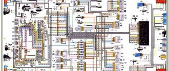
Scheme of carburetor VAZ 2105
This is a color diagram of the electrical equipment of the VAZ 2105. At the top of the image on the right are the colors of the wires, at the bottom are the designations of the elements.
1 – block headlights, 2 – side direction indicators, 3 – battery, 4 – starter activation relay, 5 – electro-pneumatic valve for the carburetor forced idle economizer, 6 – starter, 7 – carburetor microswitch, 8 – generator 37.3701, 9 – headlight cleaners , 10 – sound signals, 11 – spark plugs, 12 – engine compartment lamp, 13 – oil pressure warning lamp sensor, 14 – coolant temperature indicator sensor, 15 – ignition distributor, 16 – brake fluid level sensor, 17 – ignition coil, 18 – windshield wiper, 19 – electric headlight washer motor, 20 – electric windshield washer motor, 21 – control unit for the electro-pneumatic valve of the carburetor forced idle economizer, 22 – ignition switch, 23 – ignition relay, 24 – relay-interrupter for direction indicators and hazard warning lights, 25 – reverse light switch, 26 – brake light switch, 27 – windshield wiper relay, 28 – mounting block, 29 – socket for portable lamp, 30 – glove box lighting lamp, 31 – VAZ-2105 cigarette lighter, 32 – heater fan electric motor, 33 – parking brake warning lamp switch, 34 – carburetor air damper warning lamp switch, 35 – three-lever switch, 36 – hazard warning switch, 37 – instrument lighting switch, 38 – external lighting switch, 39 – lamp switches located in the door pillars, 40 – fog light circuit fuse, 41 – oil pressure warning lamp, 42 – rear fog light switch, 43 – fuel reserve warning lamp, 44 – instrument cluster, 45 – battery charging warning lamp, 46 – breaker relay parking brake warning lamp, 47 – interior lamps, 48 – parking brake warning lamp, 49 – carburetor air damper warning lamp, 50 – warning lamp block, 51 – rear fog light warning lamp, 52 – rear window heating warning lamp, 53 – brake fluid level indicator lamp, 54 – voltmeter, 55 – side light indicator lamp, 56 – turn signal indicator lamp, 57 – speedometer 2105, 58 – headlight high beam indicator lamp, 59 – heater fan switch, 60 – rear window heating switch, 61 – additional resistor for the heater electric motor, 62 – plug connector for connecting the bar, 63 – rear lights, 64 – license plate lights, 65 – fuel gauge sensor, 66 – rear window heating element.
Wiring diagram 2105 - full view:
Instrument panel and controls of VAZ-2107
1 — switch lever for windshield wipers and washers of the windshield and headlights. It is energized if the key in the ignition switch is in position I or III. At lever position:
2 — sound signal switch. Constantly under voltage. 3 — direction indicator switch lever. It is energized if the ignition key in the ignition switch is in position I. When the lever is moved to position “A”, the right turn indicators are turned on, and in position “B” - the left turn indicators. When the car enters the straight line after a turn, the lever automatically returns to its original position. This operation can also be performed manually. 4 — headlight switch lever. When you press the external lighting switch 17 to the second fixed position and if the key in the ignition switch is in position I or III, and the switch lever is in position:
5 - side nozzles of the interior ventilation and heating system. 6 — headlight hydraulic corrector. By rotating the handle, depending on the vehicle load, the angle of the headlight beam is adjusted so that oncoming drivers are not dazzled.
7 — engine hood lock drive lever. 8 — socket for connecting a portable lamp.
10 — alarm switch. When you press the button, all direction indicators and the warning lamp in the button itself turn on. The hazard warning lights turn off when the button is pressed again.
11 — clutch pedal. 12 — brake pedal. 13 — heater cover lever. 14 — switch (rheostat) for instrument lighting. Is energized when the external lighting is on. Rotating the handle turns on the lighting of the devices and adjusts their brightness. 15 — accelerator pedal. 16 - place for the radio. 17 — external lighting switch. When you press the upper arm of the key before the first fixed position, the side lights and license plate lights are turned on, and before the second, the headlight circuits are additionally energized. In a variant, a switch is installed. 18 - rear fog light switch. The lights in the rear lights are turned on in conditions of limited visibility (snow, fog, etc.) by pressing the upper arm of the button with the headlights on. In this case, the lamp in the key itself signals that the lights are turned on and simultaneously illuminates the key. 19 — parking brake lever. By moving the lever up, the brake pads of the rear wheels are activated. To return the lever to its original position, you must press the button at the end of the lever handle. In case of emergency, the parking brake can be used while the vehicle is moving to slow down, or used simultaneously with the service brakes. 20 - backup warning lamp. In the variant version, if the car is equipped with seat belts with an alarm for driver unfastened seat belts, a “Fasten seat belts” warning lamp is installed. 21 - backup warning lamp. On a car equipped with a fuel injection system, the “CHECK ENGINE” warning lamp is connected (check engine). A short-term lighting of the lamp when the ignition is turned on indicates a self-test of the system and is not a sign of its malfunction. 22 - rear window heating switch. The rear window heating is turned on by pressing the upper arm of the button with the ignition on. 23 - plug. 24 — gear shift lever. The gear shift diagram is printed on the lever handle. 25 - hours. To move the hands, pull the handle towards you and rotate it counterclockwise. 26 - cigarette lighter. To use, you need to press the button on the cartridge, which after about 15 seconds automatically returns to its original position, ready for use. When the instrument lighting is turned on, a special lamp illuminates the cigarette lighter socket. 27 - indicator lamp for turning on the heated rear window. Lights up orange when the rear window heating is turned on.
28 — control lamp for the fluid level in the hydraulic brake reservoir. The lamp lights up with a constant red light if the fluid level in the reservoir has dropped below the permissible limit due to fluid consumption or due to system damage. To check the serviceability of the lamp itself, it lights up if the parking brake lever is raised. 29 - ashtray. 30 — glove box cover. To access the glove box, you need to turn the lock handle clockwise and open the lid. If the key in the ignition switch is in position I or III, the inside of the box is illuminated with a special flashlight. 31 - storage shelf.
LED lighting for VAZ-2105 devices
So we buy these BLUE LEDs (you can either white or green, to your taste)
Pay attention to the LED lens made in the form of a funnel; such a lens scatters the light of the LED and it is advisable to use just such diodes. Why blue? With blue LEDs there is a very interesting effect - it seems as if the needle and instrument scales are glowing - like in foreign cars. There is no such effect with white diodes. I don’t know about the other colors. How many diodes will be required? I have a modified instrument cluster (it costs a tachometer and oil, gasoline, temperature from a VAZ 2106, you can read about it HERE) for small instruments I used one diode each, and for large ones (speedometer and tachometer) 4 diodes and one diode lamp. A diode lamp looks like this
they are inserted instead of standard light bulbs. But it makes no sense to insert them into devices instead of ordinary lamps (they will not shine normally). So, we take out the devices and disassemble them. To do this, use a screwdriver to bend the chrome ring around the perimeter. So that it can be removed from the device. The ring will of course be damaged, but it won’t be visible from behind. We remove the ring. And remove the glass from the device. There are two nuts or screws on the back of the device; unscrew them and remove the device from the housing. Next, we study small instruments (in the case of a five-piece torpedo, this is a voltmeter), the visible part of the scale, or rather the scale and the black pad above it. There is a distance between them into which we will push the diode. We take a drill with a drill bit of 7 and make a hole like this from the very bottom of the scale.
And we glue the LED onto the second black cover with sealant. Like this
Instrument panel VAZ 2101
The dashboard makes driving a car more comfortable, so it should be convenient and simple to use, displaying important information to the driver.
The standard dashboard of the VAZ 2101 has a limited number of instruments and indicators and is characterized by rather dim backlighting
The instrument panel of the VAZ “kopek” consists of the following elements:
- 6 indicator lights;
- 3 pointer instruments;
- 1 digital indicator.
Instruments and indicators of the VAZ 2101 instrument panel: 1 - fuel reserve warning lamp; 2 — fuel level indicator; 3 — speedometer; 4 — liquid temperature indicator in the engine cooling system; 5 - warning lamp for turning on the parking brake and signaling an insufficient level of brake fluid in the reservoir; 6 — control lamp for oil pressure in the engine lubrication system; 7 — battery charge indicator lamp; 8 — trip counter; 9 — control lamp for turning on the direction indicators; 10 — control lamp for turning on the side light; 11 — control lamp for turning on the high beam headlights
The panel equipment also includes:
- speedometer;
- odometer;
- coolant temperature gauge;
- fuel level indicator;
- fuel reserve warning lamp;
- block of warning lamps: activation of the parking brake and signaling of insufficient level of brake fluid in the reservoir;
- oil pressure in the engine lubrication system;
- battery charge;
- turning on the direction indicators;
- turning on the side light;
- turning on the high beam headlights.
Which one can I put?
If you are not satisfied with the design of the VAZ 2101 dashboard, it can be replaced or updated as follows:
- buy and install a more modern version, which is equipped with an on-board computer, which will not be cheap;
- update the dashboard by replacing instrument scales and arrows;
- install a device from another car.
When choosing an instrument panel, you need to take into account that the configuration may differ significantly and is not at all suitable for the “classics”. In this case, you will need to make adjustments according to the seat in the front panel.
From another VAZ model
On a VAZ 2101, it is possible to install a homemade dashboard using instruments from a VAZ 2106. It can use a speedometer, tachometer, temperature and fuel level indicator, which will look more informative compared to the standard instrument panel. Connecting the indicators should not raise any questions, with the exception of the tachometer: it must be connected in accordance with the “six” diagram.
Generator circuit 37.3701 VAZ 2105
| Position number on the diagram | Explanation of the position on the diagram |
| 1 | current storage |
| 2 | negative diode |
| 3 | additional diode |
| 4 | magneto |
| 5 | positive diode |
| 6 | stator winding |
| 7 | voltage regulator |
| 8 | rotor winding |
| 9 | RFI suppression capacitor |
| 10 | relay and fuse block |
| 11 | Electricity storage charge indicator light on the instrument panel |
| 12 | voltmeter |
| 13 | ignition relay |
| 14 | ignition switch |
Connection diagram for generator G-222 VAZ 2105
Electrical circuit for checking the voltage regulator of the generator 37.3701 VAZ 2105
Electrical circuit for checking the voltage regulator of the generator G-222 VAZ 2105
Removing the dashboard of a VAZ 2107
“Tidy” VAZ 2107 is a set of indicators and instruments that help the driver monitor the condition of the car, performance of systems and speed. The dashboard also includes the heating and ventilation control panel of the “seven”.
Before removing the dashboard, be sure to disconnect the battery ground terminal.
Further operations are performed in the following sequence:
- remove the plastic handles from the heating and ventilation control levers;
- pull out the handle of the daily mileage reset button;
- remove the decorative trim of the self-tapping screw securing the instrument panel;
- Unscrew the fastening screw using a Phillips screwdriver and pull out the panel;
Installation of a tachometer from a VAZ 2106 on a VAZ 2105
At one time, having successfully equipped the dashboard of the VAZ 2103 with such an important device as a tachometer, the developers of subsequent VAZ modifications began a series of incomprehensible experiments, as a result of which the truly successful VAZ 2105 model was left without this convenient device. However, not all owners of the “five” are ready to put up with such a defect, especially since with some effort and skillful hands, the tachometer from the kit of the later VAZ 2106 can not only be successfully installed on the dashboard of the VAZ 2105 (at the location of the combination water-gasoline indicators and battery-oil lights), but will also fully perform its functions.
So, to complete the task you will need:
- “Beard” modification of the VAZ 2107. However, another one will do, the main thing is that it provides for the placement of instruments;
- A set of instruments from a VAZ 2106, namely indicators for oil, gasoline and water and, of course, the tachometer itself;
- Wires with a total length of 9m. In our case, it will be 1 m of white wire for the general minus, 1 m of red for the general positive, 1 m of green wire to connect the temperature sensor, one meter of yellow wire to provide general illumination, 1 m of pink wire for the gasoline sensor and three gray wires of 1 m each for connection emergency fuel reserve lamps, oil sensor and oil pressure (the oil pressure circuit is created by analogy with the VAZ 2106 and, if desired, can be abandoned);
- Connection block for 8 contacts assembled “male” and “female”;
- An additional oil pressure sensor and, accordingly, a tee for connecting it (again, to introduce a successful oil pressure alarm as on the “six”).
After all the necessary components are at hand, we carry out preliminary wiring of the wires going to the devices, gasoline, water, oil, for which we solder them together:
- White wires with a black stripe, intended for connecting the common negative (marked as “BN” on the device terminals);
- Red wires are common positive (labeled “C”);
- White backlight power wires (marked as “B” on devices).
- As a result, at the output of the instrument cluster we should receive one red “positive” wire, one white wire with a black stripe of a common “minus” and one white wire for connecting the backlight.
Next, we insert the three wires of the combined circuits we received into the contact block of the “male” version that we purchased (indicated by number 1 in the diagram). After that, we pack in the same part of the 8-pin block:
Possible faults
Dismantling and repair of the device may be required for the following malfunctions:
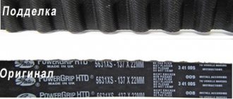
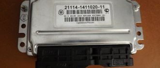
When repairing or replacing the instrument panel (instrument panel) of VAZ cars with a more modern and convenient version of VDO, made with LEDs, you will need connection diagrams and pinouts for the connectors. panels for this, the editors of 2SHEMI.RU have prepared a collection complete with pinouts of panel contacts for all popular models of this car.
The main symbols that are found on the dashboard of absolutely any car of the VAZ family are: speedometer, fuel gauge, tachometer and sensors to indicate engine temperature.
Malfunctions of the ignition coil of VAZ 2106
There are individual malfunctions of the ignition coil that lead to replacement of the product. These include external mechanical deformations of the product and breaks in the coil windings. A malfunction of the VAZ 2106 ignition coil is classified as a condition when the ignition coil heats up to a high temperature.
Slight heating of the product is the normal state of this part when the ignition is turned on and the distributor contacts are closed with a contact ignition system. If you doubt the functionality of this part of the ignition system, we recommend checking the coil for the resistance of both windings of the product.
Pinout of the dashboard of VAZ2105, 2107, 2106
Old panel (with pressure indicator except)
oil presence of an oil pressure indicator, it is worth noting that in this instrument panel there is no lamp indicating the air damper (choke), and the emergency oil pressure lamp is located next to the pressure indicator. Because of this, it contains lamps for low brake fluid level and fog lamps.
White 6-block terminal X1:
- Gasoline level sensor
- Turn signal indicator lamp
- Battery charge sensor (Control -)
- voltmeter gasoline level lamp
- General Sensor (+)
- plus battery charge (voltmeter +)
White 8-block terminal X2:
- Fog lamp warning lamp
- high beam warning lamp
- Indicator lamp Empty
- dimensions
- Battery charge indicator lamp
- Brake fluid level indicator lamp
- Empty
- Parking brake warning lamp
Orange 6-terminal Common X3:
- block minus (-)
- Tachometer VAZ
- Backlight Sensor
- oil pressure gauges
- Oil pressure warning lamp
- Coolant temperature sensor
New instrument panel (with econometer)
White 6-pin Sensor X1:
- gasoline level block
- Turn signal indicator lamp
- Battery charge sensor (voltmeter -)
- Gasoline level control lamp
- Overall plus (+)
- charge Battery sensor (voltmeter +)
White 8-pin Control X2:
- size lamp block
- High beam warning lamp
- Oil pressure warning lamp
- wiring, but in the Empty there is a terminal going to the brake fluid level sensor
- Charge indicator lamp
- Battery lamp of the air damper (choke) of the unit or engine control for injectors
- Control
- Empty parking brake lamp (handbrake)
Terminal 6-Orange block X3:
option of the Second connection scheme
Pinout of the dashboard of VAZ2113, 2115, 2114
There are 26 contacts on the VAZ-2114 instrument panel, each of which is responsible for the operation of this panel indicator. If each contact is supplied to the panel, then the plus contact demonstrates information about which state the car is currently in.
White block (X1)
Red block (X2)
In addition, special indicators and feed sensors are installed on the instrument panel, and the signals are controlled by the panel using a special electronic unit. Having disassembled the instrument panel, you can see that there are two pads inside it: red and white. And all inputs, fuses and outputs are connected to the plug. If the sensors fail, they will need to be replaced. It is also better to replace damaged or oxidized wires. Controls, like light bulbs and any others, sometimes burn out. it is necessary to undoubtedly replace them with whole ones. Along with them, the lamp sensor often burns out.
VAZ 2114 panel instrument connection diagram
- rear window heating switch;
- rear fog lamp switch;
- light switch for headlights and direction indicators;
- mounting switch;
- windshield wiper unit;
- fog light switch;
- indication block of the on-board control system;
- instrument harness panel block to additional harness;
- combination block;
- instrument panel harness to harness block;
- on-board computer instrument panel harness to system ignition harness;
- instrument panel harness connector to side door harness;
- fuse 16 A;
- fuse 16 A;
- switch switch;
- ignition for lighting;
- heater electric motor;
- additional electric motor heater resistance;
- relay lock unloading relay;
- ignition of rear fog lights;
- relay socket;
- starter for connecting a portable lamp;
- cigarette lighter;
- harness of the instrument panel block to the glove box lamp lighting wiring harness;
- illuminator;
- illuminator;
- switch;
- heater light;
- instrument lighting regulator with switch;
- brake signal rheostat;
- sound switch;
- alarm signal;
- pablo heater control illumination lamp;
- fuse 16 A;
- heating relay Useful;
Another scheme for pinout of connectors
- checking the brake fluid level indicator. If you apply +, the brake light will come on. You can connect it to the red ignition wire of the lock, then, just like on the 2110/lamp 2114, the lamp will be checked when turned on.
- starter hazard warning lamp, the + lamp will light up.
- high beam supply, connect to the green-black wire.
- fuel level indicator, connect to the red-pink wire.
- to the speed sensor.
- signal speed output to the on-board computer. If it is there, then take the speed signal from this contact.
- Brake fluid level indicator, connect to the pink-blue lamp near the wire above the cigarette lighter. In the VAZ-2107, the lamp works the other way around: the sensor connects the lamp to the ground and lights up. You will have to either leave the lamp there where it is, or in the new unit, solder the lamp to + and swap places when (diodes in this case, to check the lamp, you need to connect 1 contact to ground, for example to a lamp or), connect the black wire to the handbrake sensor on the tank, and instead remove the orange one from the block or, EPHH blue from the ignition coil, while the diode in the wiring (between the beard and the glove compartment) must be disconnected, if this is not done, there will be a short circuit.
- left turn lamp, connect to the black-blue wire of the steering column switch pad.
- right turn signal lamp, connect to the blue wire of the steering column switch block.
- instrument lighting, connect to the white wire.
- ground, connect to the black wire.
- devices power supply, connect to the orange wire.
- if the device is simple (without microcircuits, etc.), then connect it to the blue-red wire (fuel reserve lamp), if the tachometer has a display, then connect it to the sensor (temperature from the VAZ-2114, one contact to the other, tidy to ground, place it either in the engine compartment or in the engine compartment, but so that it is far from the engine and so that the wind does not blow).
- ground, connect to the white-black wire.
- low voltage tachometer input (from the ECM), brown to connect-blue wire.
- high-voltage coil input (from the tachometer), connect to the brown-blue wire.
- If there is a display under the speedometer, then connect it to the white-red wire at the brake light switch.
- coolant temperature gauge, connect to the green-white wire.
- outdoor lighting lamp, connect to the yellow wire.
- Connect the choke cover lamp of the carburetor to the gray-orange wire.
- go to the ECM lamp. If the machine is injection, then connect one of the contacts to the orange wire, and the other to the remaining one.
- the lamp goes to the ECM. If the machine is injection, then connect one of the contacts to the orange wire, and the other to the power supply.
- connect the remaining devices to the orange-blue lamp.
- handbrake wire, connect to the brown lamp.
- battery charge wire, connect to the brown-white wire.
- Low oil pressure lamp, gray to connect-blue wire.
Instrument panels VDO VAZ (LED)
Dashboard indicators of the VAZ panel play an important role in informing the user about malfunctions. They help prevent errors in the operation of the system, so it is important to know what the indicator means. How's the panel? works If any problem occurs, the sensor immediately sends information to the panel, and the driver who lights up will see an orange signal.
The instrument panel of the earlier version also had some symbols, for example, emergency oil pressure, manual brake, Engine Chek signal and several others, indicating minor errors, but which are not used now.
Repair or replacement of VAZ dashboard
If none of the indicators installed on the instrument panel on the car (speedometer, odometer, tachometer, fuel level and coolant temperature indicators) work, then the first thing the driver will have to do is check the integrity of fuse F3, which is located in the mounting block . If it burned out, then before replacing it, you need to find the reason why it burned out, otherwise a new fuse installed again will have the same fate as the previous one. Most often, fuses burn as a result of a short circuit.
To replace the serviceability of the ignition relay, the probable working causes of the condition of the instrument panel, there are only two left: the ignition switch and the mounting block. Before the VAZ-2109 car was installed, the ignition relay and lock contacts often burned out and had to be cleaned by disconnecting the contact group from the lock itself. After changes were made to the principle of supplying voltage to the lock, the ignition contacts began to burn out; it is very likely, but rarely, that this phenomenon still remained. On the mounting block, in its board, the tracks may burn out; in order to see this, the mounting block will have to be removed from the car.
In addition to the reasons listed above, which can lead to a failure of the instrument panel, it is also necessary to check the reliability of the ground wire fastenings. The most common problems:
- burnout of incandescent lamps or failure of the output of the LED group;
- oxidation of connectors;
- electrical wiring malfunction;
- failure of the fuse box;
- general damage to the contact board;
- absence of mass on the minus (body) or damage to the dimensions system.
To find the fault, you must use a diagnostic tester, equipment or voltmeter. If any damage is found, repairs can begin.
Difficulties in repairing electrical equipment
The biggest problem that can arise during repair work on a VAZ-2105 is a mismatch in the color of the wiring with that indicated in the diagram.
If the car is many years old, then most likely the wiring has been replaced many times. The previous owner of the car was unlikely to be concerned that the wiring colors did not match the colors in the diagram. Most likely, if a car needed urgent repairs, the first wires that came to hand were installed on it. Therefore, a new car owner will have to face difficulties and figure out which wire is connected where. In this case, you can immediately make some adjustments for yourself in the future using felt-tip pens. During repairs, you can paint each wire in the desired color, this can save time for the next inspection or diagnosis. Another difficulty that a car owner may encounter when repairing a VAZ-2105 is partial replacement of the wiring. The previous owner could only replace part of the wires, thereby causing the current owner a lot of trouble. This situation causes even more confusion, and in this case it would make more sense to simply replace all the wiring.
The most common reason for a VAZ-2105 breakdown is damaged wire insulation or lack of contact. In this situation, it is necessary to test all sections of the wiring using a special device. The non-working electrical wiring is replaced with a new one, or part of the non-working wire can be replaced. If the insulation is damaged, then use electrical tape to eliminate this problem.
Removing the car dashboard
- using a Phillips screwdriver, remove the self-tapping screws that secure the central one;
- console trim, protrusion located at the bottom, remove the protrusion from the bracket;
- Using a nozzle, unscrew the five screws located in the console on the right, remove the screen;
- Disconnect the terminal with the (-) sign from the battery. If there is a radio receiver, you need to remove it, remove the shield from the plug;
- Disconnect the wires coming from the cigarette lighter and remove the cartridge;
- Using a narrow screwdriver, remove the handle from the levers;
- pull the handle towards the heating and fan switches;
- unscrew the two screws above the panel and the two located under it using a screwdriver;
- Unscrew the self-tapping screw with the panel facing it;
- Also unscrew the two self-tapping screws securing the cover;
- disconnect the harness and wire connectors. When installing the panel there is no confusion, the order of their connection should be marked;
- unscrew the bolts;
- the fastenings are two self-tapping screws, the ones that secure the bottom bracket using a size 8 wrench;
- unscrew the fastening screw of the light guide and remove it;
- Also unscrew the self-tapping screws securing the heating unit;
- remove lamp sockets;
- after removing the external parts, remove the decorative insert;
- unscrew all the hydraulic corrector nuts by 21;
- use a key to remove the lamp;
- unscrew which, the screws are attached to the cross member located on the left.
- At the end the panel itself is removed. The panel assembly is accordingly carried out in the reverse order.
Installation and repair instructions
Dismantling the control panel may be required for repairs, tuning the panel, replacing sensors, etc. The procedure is simple and can be performed at home.
Tools and materials
To disassemble and repair the dashboard, you must prepare the following tools and materials:
- a set of keys;
- Screwdriver Set;
- diagnostic tester;
- new sensors and parts needed for replacement;
- elements for tuning.
It is better to buy originals to avoid fakes.
Algorithm of actions
To dismantle the tidy, you need to perform the following steps:
- Turn off the power supply to the machine by disconnecting the negative terminal from the battery.
- After unscrewing the mounting bolts, you need to remove the casing from the steering column.
- By removing the plugs and unscrewing two screws, the instrument panel is removed.
- Next, the wire plugs are disconnected.
- After opening the glove compartment, you need to unscrew the mounting bolts. The bolts securing the shelf for things are unscrewed in the same way.
- By pulling the handle of the hydraulic light corrector, you need to remove it. Then, using a socket wrench, unscrew the mounting nut and push it in.
- In the glove compartment, disconnect the power cord for the backlight lamp.
- After unscrewing the two bolts, you need to move the heater control unit.
- Next, you should dismantle the air duct.
- The next step is to unscrew all the console fasteners.
- When the last two fastening nuts in the center are unscrewed, you need to carefully remove the panel from the studs and remove it from the interior.
Next, the necessary repairs, tuning, replacement of sensors are performed, and backlighting is installed. After completing all the manipulations, the assembly of the device is carried out in the reverse order of disassembly.
To make assembly easier, during disassembly you should mark the wires and sort the devices and sensors.