The collection of diagrams is intended for professional auto electricians and amateurs to help them perform small repairs on auto electronics with their own hands. At the end, see links to download useful literature on LADA.
I am posting a wiring diagram with explanations.
I am posting a wiring diagram with explanations.
Post by Wizard » 07 Feb 2014, 21:58
I am posting a wiring diagram with explanations. Maybe I should stick it up somewhere, in a separate topic?
1 – front lights; 2 – side direction indicators; 3 – headlight washer electric motor*; 4 – voltage regulator; 5 – battery charge warning lamp relay; 6 – battery; 7 – starter; 8 – generator; 9 – headlights; 10 – gearmotors for headlight cleaners*; 11 – sound signals; 12 – spark plugs; 13 – carburetor solenoid valve; 14 – ignition coil; 15 – windshield wiper gearmotor; 16 – coolant temperature indicator sensor; 17 – ignition distributor; 18 – windshield washer electric motor; 19 – oil pressure indicator sensor; 20 – oil pressure warning lamp sensor; 21 – brake fluid level warning lamp sensor; 22 – plug socket for a portable lamp; 23 – relay for turning on headlight cleaners and washer*; 24 – relay for turning on low beam headlights; 25 – relay for turning on the high beam headlights; 26 – windshield wiper relay; 27 – additional fuse block; 28 – main fuse block; 29 – additional resistor of the heater electric motor; 30 – reverse light switch; 31 – brake light switch; 32 – heater electric motor; 33 – relay-breaker for alarm and direction indicators; 34 – parking brake warning lamp switch; 35 – alarm switch**; 36 – cigarette lighter; 37 – switch for cleaners and headlight washers*; 38 – heater motor switch; 39 – external lighting switch; 40 – three-lever switch; 41 – ignition switch; 42 – instrument lighting switch; 43 – lamp switches located in the door pillars; 44 – interior lamps; 45 – oil pressure gauge with insufficient pressure warning lamp; 46 – fuel level indicator with reserve warning lamp; 47 – tachometer; 48 – parking brake warning lamp; 49 – battery charge indicator lamp; 50 – control lamp for the carburetor air damper; 51 – side light indicator lamp; 52 – turn signal indicator lamp; 53 – control lamp for high beam headlights; 54 – speedometer; 55 – switch for the carburetor air damper warning lamp; 56 – relay-interrupter for the parking brake warning lamp; 57 – coolant temperature indicator; 58 – brake fluid level warning lamp; 59 – differential lock warning lamp; 60 – switch for differential lock warning lamp; 61 – rear lights; 62 – license plate lights; 63 – sensor for level indicator and fuel reserve.
The order of conditional numbering of plugs in blocks:
a – windshield and headlight wipers, windshield wiper relay breaker; b – relay-breaker for alarm and direction indicators; c – three-lever switch; d – hazard warning switch.
* Installed on parts of manufactured cars; ** on cars produced in the 90s, due to the installation of breaker relays 33 without the fifth terminal, the brown wire connecting switch 35 to breaker relay 33 is missing.
Engine control system fuses
Purpose and parameters of fuses in the block (from left to right):
- 1 — ensuring the start of the electric motor of the right fan (rated 30 A);
- 2 — similar fuse-link for the left fan;
- 3 - fan relay, as well as the injection system control unit, control of injection nozzles and ignition coil (rated 15 A);
- 4 - system for reducing gas toxicity - heating of lambda probes, fuel vapor trap valve and sensor for measuring the volume of air entering the engine (rated 15 A);
- 5 - diagnostic connector for monitoring the operating parameters of the injection system.
On some VAZ 21214 with an ABS system, a fuse block with 7 inserts is installed.
Block Niva Urban
Assignment of fuses (numbering starts from the door opening).
| Number | Rated current, A | Purpose |
| PR01 | 15 | Sensors on the engine, gasoline vapor trap, starter |
| PR02 | 15 | Fans, engine operation systems (control unit, ignition, injectors) |
| PR03 | 30 | Fan starting system |
| PR04 | 15 | Gasoline pump |
| PR05 | 5 | ABS unit |
| PR06 | 40 | Likewise |
| PR07 | 25 | Likewise |
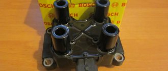
Engine Control Relay Box
The engine control relay diagram is shown in the photo.
Engine control relay
The block contains the following relays (from left to right):
- 1 — ignition activation;
- 2 - main relay, which serves to start all engine systems;
- 3 — starting the right fan on the radiator;
- 4 — start of the left fan;
- 5 — ensuring the operation of the fuel pump;
- 6 - safety element of the fuel pump power supply circuit with a rating of 15 A.
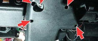
Relay block diagram above the gas pedal
The diagram of the block with the relay, which is located slightly deep in the instrument panel and is responsible for lighting the car, is shown in the photo.
The purpose of the relay in the block (from left to right) is given in the table.
| Position | Purpose |
| 01 | Rear fog lamps |
| 02 | Heated glass on the rear door |
| 03 | Low beam |
| 04 | High beam |
Wiring diagram VAZ 2131 Niva injector
VAZ 21 31 NIVA “Long”
Production since
1993
VAZ-213100 LADA 4×4 —
engine 21214 engineer
61.00 kW/83 hp catalyst, Euro-4, weight - 1425/max 1850 kg. (data from the car produced in 2012) hydraulic power steering, new “torpedo”, instrument panel 2115, front seats of the 12th series, plastic door trim and other changes. As of 2012, this version was the only one available for purchase through the AvtoVAZ retail network (among 5-door ones), while among the “short” ones there was a choice of configurations. VAZ-213102 is
a “civilian” modification with a 5-door body based on the VAZ-2131SP (213105).
It was equipped with a five- or seven-seater (on request) interior. Trunk volume 1900 l. Produced to order in 2001-2005; VAZ-213145 is
a modification of the VAZ-2131SP with a VAZ-21214-20 (-30) injection engine that complies with Euro-2 (Euro-3) standards.
Produced in small series since 2006. VAZ-2129 (“Cedar”) is
a small-scale model, extended by 500 mm, with a 3-door body based on the standard VAZ-21213.
It was produced in small batches at the AvtoVAZ production plant in 1992-1994, becoming the immediate predecessor of the VAZ-2131; VAZ-2130 (“Cedar”) is
a small-scale extended model with a 3-door body.
Unified with the VAZ-2129 model except for the interior layout: the rear seat of type 2108 was extended from the wheel arches; LADA-BRONTO-1922-50 “Marsh-Long” is
an all-terrain vehicle on ultra-low pressure wheels (pneumatic engines or “pneumatics”) using Niva components and assemblies and a 5-door VAZ-2131 body.
Produced to order by JSC SPA BRONTO since 2004; LADA-BRONTO-1922-51 “MARCH-RESCUER” is a
specialized snow and swamp-going vehicle on ultra-low pressure wheels (pneumatic propulsion or “pneumatics”) using Niva components and assemblies and a 4-door VAZ-2131SP body (without an extended rear overhang).
Designed for rescue and medical services. Produced to order by JSC SPA BRONTO since 2005; LADA-BRONTO-1922-55 "MARSH-COMBI" -
a cargo-passenger version of the "Marsh-Long" snow and swamp-going all-terrain vehicle with increased body volume.
Produced to order by SPA BRONTO OJSC since 2008. ANTEL is
an experimental model based on the VAZ-2131, the power plant of which runs on hydrogen.
Location of the diagnostic connector: 1The diagnostic connector is located to the left of the driver's feet.
ECU location: 1
The controller on Nivas is located in the same place as the diagnostic connector to the left of the driver’s feet. To access it you need to unscrew the plastic shield.
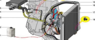
The engine cooling system is liquid, closed type, with forced circulation of liquid.
The exhaust system is a set of muffler elements connected to the exhaust manifold. It is possible to install an exhaust gas catalyst into the gap between the exhaust pipe and the resonator.
Single-disc, dry, with a diaphragm-type central spring.
Front suspension - independent, wishbone, spring, with hydraulic telescopic shock absorbers and anti-roll bar Rear suspension - wishbone, spring, with hydraulic telescopic shock absorbers
The front brakes are ventilated discs. The rear brakes are drum brakes.
BODY
4-door, sedan (5 seats)
Every modern car today is equipped with an electrical part. The electrical diagram of the VAZ 21214 Niva injector allows, if necessary, to find all the elements included in the on-board network, which is especially important when faults occur in the wiring. Everything a driver needs to know about electrics in domestic SUVs is described in this article.
Niva index designations
Differences in generators
Wiring differences
Photo gallery "Electrical systems of SUVs"
Video “Laying wiring in the sports version of the Niva”
Comments and Reviews
Dashboard
For subsequent modifications of the VAZ 2121, the instrument panel was thoroughly redesigned. In particular, the design and location of the warning lamps have changed, and new scales have appeared on the instrument panel indicators.
Original wiring diagram for VAZ 21214 – instrument panel and warning lamp harness
All control devices are interconnected. This combination consists in particular of:
- speedometer;
- tachometer;
- coolant temperature indicator;
- 12 indicator lamps;
- battery charge sensor;
- fuel level indicator.
DETAILS: VAZ 2131 Niva: price of VAZ 2131 Niva, technical characteristics of VAZ 2131 Niva, photos, reviews, video
All of them are located on the panel.
The schematic diagram shows the combinations available on the instrument panel:
- tachometer (1);
- stabilizer (2);
- panel illumination (3);
- coolant heating indicator (4);
- gasoline level (5);
- toxicity reduction systems (6);
- heated luggage door glass (7);
- fog lights (8);
- high beam (9);
- outdoor lighting (10);
- turn signals (11);
- TG level (13);
- oil pressure (14);
- differential locks (15);
- fuel reserve (16);
- seat belts (17);
- parking brake (18).
D1, D2 are diodes (type IN4002).
Cars manufactured before 1996 also have a voltmeter (12 in the diagram).
Finally, there are two resistors:
- R1 – at 470 Ohm (0.25 W);
- R2 –51 Ohm, (5 W).
Niva index designations
Detailed electrical diagram of Niva
The wiring diagram may vary slightly depending on the design features of the vehicle.
First, let's look at the index notation:
- VAZ 21213. This index designates a vehicle equipped with a carburetor. The volume of the power unit is 1.7 liters.
- 21214. In VAZ 21214 cars, the scheme involves the use of a similar engine with the same volume. The only difference is that the car is equipped with a fuel injection system.
- There is another model with the index 21213. In VAZ 21213 cars, the electrical circuit includes the same elements, only depending on the year of manufacture, the car can be equipped with a 1.8 liter engine.
- Version 21073. The SUV is equipped with either an injection engine with nozzles or a Solex carburetor engine. One of the features of these cars is a contactless ignition circuit.
- 21215. These SUVs were originally produced for export, so these cars are difficult to find on our roads. It is worth noting that they were equipped with Citroen diesel engines.
At the beginning of the article there is a diagram of the VAZ electrical equipment using the example of the Niva 2121 model. If you are the owner of version 2131 or any other, then there will be a difference in the circuit diagram, but not fundamentally. If we are talking about carburetor engines, then in this case the battery charging circuit, as well as the ignition, will not be protected (video author - Nail Poroshin).
Generator Differences
One way or another, the electrical diagram of any vehicle, be it model 2131 or 21073, is drawn up depending on the type of engine. If it is a carburetor, then the electrical wiring will have certain differences. For example, models characterized by fuel injection must be equipped with a more powerful generator, since they have a higher load on the electrical wiring.
Based on this:
- On version 21213, the manufacturer decided to install a generator device marked 371.3701.
- As for versions 21214, here we also had to use a more powerful generator. Its model is 9412.3701.
And also interesting: Niva VAZ 21213 engine: characteristics, malfunctions and tuning || Niva 1996 engine
It should be noted that despite the different models, these devices are similar in design. In essence, they are synchronous alternating current devices. They are also characterized by the presence of a built-in rectifier, as well as an output voltage regulator, which is important.
Features of electrical equipment
The electrical circuit of the VAZ model 21213 has certain differences with the model 2121, in particular:
- 21213 vehicles use more modernized foot fuses in the fuse box. Of course, the use of such devices led to the fact that the block site also became different.
- The power supply system of these vehicles additionally includes an idle speed saving device. For this option to work properly, another connector with wiring was added in the engine compartment.
- Another difference is that these cars use a non-contact ignition circuit, the main element of which is a microcontroller.
It should be noted that differences in the Niva circuit may lie both in the generator units and in the electrics themselves.
Differences in generators
In any case, the differences in the wiring diagram of the models will primarily depend on the power unit - carburetor or injection.
The main differences in carburetors:
- models 21213 use the generator unit model 371.3701;
- in the engines of models 21214, the manufacturer decided to install a more powerful generator device; it is marked with the numbers 9412.3701 (video author - Sergei Chekhonin).
And although these generators are different, they have certain similarities in design. In any case, it is a synchronous AC device. In addition, these units have a built-in rectifier and output voltage regulation mechanism.
Wiring differences
If we talk directly about wiring, then depending on the car model, it may also have differences. It should be noted that these differences greatly simplify do-it-yourself maintenance and repair of the system. As for injection modifications of SUVs specifically, in this case the system is equipped with three outputs intended for installing electronic ignition.
In addition, 21214 cars use two ventilating devices that perform the function of cooling the radiator assembly. Accordingly, due to the use of additional fans, the wiring also underwent, albeit not significant, differences. Of course, they are not fundamental.
Photo gallery "Electrical systems of SUVs"
Chevrolet Niva hub - replacement
Do-it-yourself improvements to Niva 2121
To replace the wheel bearing in the field, you need to pull out the hub. This is carried out according to the following plan.
1. Dismounting the conical bushing.
2. Unlocking the nuts. The problem may lie in the fact that they often lick off or turn sour. In this case, you can use a chisel and a light hammer.
3. Use the nineteenth socket or wrench to remove the lever clamps. They are located both front and back.
4. The locking plates are removed. These are metal perforated strips that are often overlooked.
5. The seventeenth and tenth keys require removing the circuit pipes.
6. A stop is installed under the lever. Using two twelfths keys, unscrew the nut fixed on the upper arm retainer bolt.
7. The lower block is also unscrewed in the same way.
8. When there are no fasteners left, it is possible to pull out the entire system at once.
9. By fixing the steering knuckle with a clamp, you can knock out the hub.
10. After this, the screws securing the knuckle to the lever mechanism are removed.
Knowing the structure of the front wheel hub of Niva 21213, you can carry out repairs yourself, without contacting a service center.
Summarizing
The need to understand the wiring diagram may arise if there are malfunctions in the operation of the system and they need to be eliminated. Of course, complex malfunctions associated with the operation of the generator unit and other devices that are not simple in terms of design will be problematic to solve in a garage without certain knowledge. However, even simple knowledge of the electrical circuit and the ability to decipher the symbols can greatly help the car enthusiast during repairs. In addition, the need to understand wiring may also arise if you decide to upgrade your speakers or install a more advanced audio system.
Other breakdowns
If no blown fuses are identified, then you need to check the integrity of the wires and the reliability of the connections of the terminals and connectors. Problems often arise due to battery discharge.
Fan failure is caused by incorrect connection of the alarm system or breakdown of the starter.
Also, the fuel pump often refuses to turn on if it fails:
- control relay;
- controller;
- wiring supplying this unit.
In general, the electrical circuit contains more than 70 elements, the malfunction of any of them can negatively affect the operation of the car.
https://youtube.com/watch?v=TYFkDkxAyJc
Video “Laying wiring in the sports version of the Niva”
You can learn more about this process from the video (author - Suprotec Racing channel).
Scheme of the first VAZ-2121
Years of manufacture: 1977-1993 content-27.foto.my.mail.r…ail/mr.chvans/79/s-94.jpg With tail lights and instruments from 2106
Scheme VAZ-21213 (Carburetor)
Years of manufacture: 1993-2009 content-25.foto.my.mail.r…ail/mr.chvans/79/s-97.jpg The diagram shows a relay for rear fog lights, used since 2000, before that they were turned on directly from the latching switch.
Since 2004, the car was renamed from NIVA to LADA 4x4
Since 2013, daytime running lights began to be used: a 2-filament lamp is installed at the side lights in the side light section. When the ignition is turned on, the power comes to the 21W thread (running lights mode), when the external lighting is turned on, the power switches to the 5W thread (side lights mode).
Schemes of the carburetor mixture control system are here www.drive2.ru/b/2168677/ There is a little information about the devices at the end of this article www.drive2.ru/b/1087776/
No more information available. I'll add what I find out. If you have anything to add or correct, write in the comments.
Location of fuse and relay blocks Niva 4x4
The main part of the fuses are located in the Niva's interior under the panel to the left of the steering column. Total 4 blocks:
1 – engine control system fuse block; 2 – windshield wiper relay; 3 – fuse blocks; 4 – engine control system relay block.
The fourth relay block is located above the gas pedal.
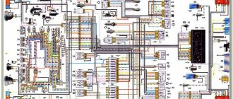
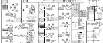
Electrical diagram of the NIVA car
A collection of several options for electrical circuits for the domestic Niva car. Color schemes are presented in good quality for Niva VAZ-21213, Niva VAZ-21214 and Niva VAZ 2121.
Wiring diagram Niva 21213
1. Front lights.2. Side direction indicators.3. Windshield washer motor. 4. Headlight washer motor*. 5. Switch. 6. Rechargeable battery. 7. Niva starter. 8. Generator. 9. Niva headlights. 10. Geared motors for headlight cleaners*.11. Sound signal.12. Spark plugs.13. Carburetor limit switch. 14. Carburetor solenoid valve.15. Ignition coil.16. Windshield wiper motor. 17. Carburetor solenoid valve control unit.18. Ignition distributor sensor.19. Coolant temperature indicator sensor.20. Insufficient oil pressure indicator sensor.21. Portable lamp socket. 22. Insufficient brake fluid level indicator sensor. 23. Windshield wiper relay breaker.24. Relay for turning on rear fog lamps. 25. Relay for turning on the rear window heating element. 26. Relay for turning on headlight cleaners and washer*.27. Relay for low beam headlights. 28. Headlight high beam relay.30. Starter activation relay.31. Relay-breaker for hazard warning lights and direction indicators. 32. Electric heater motor.33. Additional resistor for the heater motor. 34. Illumination lamps for heater control levers.35. External lighting lamp switch.36. Main fuse block. 37. Additional fuse block.38. Reversing light switch.39. Brake light switch. 40. Regulator for instrument lighting lamps.41. Ignition switch.42. Three lever switch. 43. Hazard switch.44. Switch for headlight cleaners and washers.45. Heater motor switch.46. Rear window heating element switch.47. Rear fog lamp switch. 48. Lamp switches located in the door pillars.49. Interior lighting lamps. 50. Cigarette lighter. 51. Switch for the carburetor air damper warning lamp. 52. Indicator lamp for closing the carburetor air damper.53. Switch for the differential lock indicator lamp. 54. Parking brake indicator lamp switch. 55. Level indicator and fuel reserve sensor. 56. Instrument cluster. 57. Rear window washer motor. 58. Tail lights. 59. Block for connecting additional brake lights.60. Blocks for connecting side marker indicators.61. Pads for connecting to the rear window heating element. 62. License plate lights. 63. Rear window wiper motor.
Electrical diagram of the car Niva 2121
1 — side direction indicators; 2 — front lights; 3 — headlights; 4 — electric motors for headlight cleaners; 5 — Niva sound signals; 6 — relay for turning on the headlight cleaners and washer; 7 — relay for turning on low beam headlights; 8 — relay for turning on the high beam headlights; 9 — electric motor for windshield washer; 10 — sensor of insufficient brake fluid level; 11 — plug socket of a portable lamp; 12 — oil pressure warning lamp sensor; 13 — oil pressure indicator sensor; 14 — coolant temperature indicator sensor; 15 — ignition distributor; 16 — spark plugs; 17 — electric motor of the windshield wiper; 18 — ignition coil; 19 - generator; 20 — carburetor shut-off valve; 21 - starter; 22 — headlight washer motor; 23 - voltage regulator; 24 — battery charge warning lamp relay; 25 - battery; 26 — windshield wiper relay; 27 — additional fuse block; 28 — main fuse block; 29 — parking brake warning lamp switch; 30 - switch for differential lock warning lamp; 31 — reverse light switch; 32 — switch for the carburetor air damper warning lamp; 33 — brake light switch; 34 — heater electric motor; 35 — relay-interrupter for direction indicators and hazard warning lights; 36 — additional resistor of the heater electric motor; 37 — instrument lighting switch; 38 — headlight switch; 39 — direction indicator switch; 40 — sound signal switch; 41 — wiper switch; 42 — windshield washer switch; 43 — ignition switch; 44 — external lighting switch; 45 — heater switch; 46 — switch for headlight cleaners and washer; 47 — cigarette lighter; 41 — alarm switch; 49 — lamp switches located in the door pillars; 50 — oil pressure gauge with insufficient pressure warning lamp; 51 — fuel level indicator with fuel reserve warning lamp; 52 — Niva tachometer; 53 — parking brake warning lamp; 54 - battery charge indicator lamp; 55 — control lamp for the carburetor air damper; 56 — speedometer; 57 — control lamp for external lighting; 58 — turn signal indicator lamp; 59 — control lamp for high beam headlights; 60 — relay-interrupter for the parking brake warning lamp; 61 — brake fluid level warning lamp; 62 — differential lock warning lamp; 63 — coolant temperature indicator; 64 — lampshades of VAZ 2121; 65 — sensor for level indicator and fuel reserve; 66 — rear lights; 67 — license plate lights.
Wiring diagram of Niva car harness connections
Instrument harness connection diagrams
List of elements of the electrical connection diagram of the instrument panel wiring harness assembly for cars of the LADA 4X4 family
1 - additional relay; 2 — relay-interrupter of direction indicators; 3 — windshield wiper relay; 4 — ignition switch; 5 — alarm switch; 6 — rheostat 2130; 7 — turn signal headlight switch; 8 — windshield wiper and washer switch; 9 — main fuse block; 10 — additional fuse block; 11 — instrument clusters; 12 — external lighting switch; 13 — rear window wiper switch; 14 — rear window heating switch; 15 — rear fog light switch; 16 — heater motor switch; 17 — additional resistor of the heater electric motor; 18 — heater electric motor; 19 — relay for high beam headlights; 20 — low beam headlight relay: 21 — rear window heating relay; 22 — rear fog light relay: 23 — cigarette lighter; 24 — differential engagement sensor; 25 — brake signal switch; 26 — reverse lamp switch; 27 — handbrake warning lamp switch; 28 — illuminator; 29 — illuminator; 30 — instrument panel harness block to the front harness: 31 — instrument panel harness block to the front harness; 32 — block of the instrument panel harness to the ignition system harness; 33 — instrument panel harness block to the rear harness: 34 — instrument panel harness block to the rear harness.