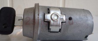
Pinout of the ignition switch VAZ-2101 - VAZ-2107
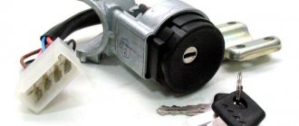
The ignition switch on these cars is located to the left of the steering column. It is fixed directly to it using two fixing bolts. The entire mechanism of the device, except for the upper part in which the keyhole is located, is hidden by a plastic casing.
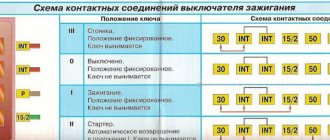
On the visible part of the ignition switch housing, special marks are applied in a certain order, allowing inexperienced drivers to navigate the lock activation mode when the key is in the hole:
- “ ” – a mark indicating that all systems, devices and instruments that are turned on using the lock are turned off (this does not include the cigarette lighter, interior lighting, brake light, and in some cases the radio);
- “ I ” is a mark informing that the vehicle’s on-board network is powered from the battery. In this position, the key is fixed independently, and electricity is supplied to the ignition system, to the electric motors of the heater and windshield washer, instrumentation, headlights and light signaling;
- “ II ” – engine start mark. It indicates that voltage is applied to the starter. The key does not lock in this position. If you release it, it will return to the "I" position. This is done so as not to subject the starter to unnecessary loads;
- “ III ” – parking mark. If you remove the key from the ignition in this position, the steering column will be locked with a latch. It can only be unlocked by inserting the key back and turning it to position “0” or “I”.
The ignition switch has five contacts and, accordingly, five terminals, which are responsible for supplying voltage to the desired unit. All of them are numbered for convenience. Each pin corresponds to a wire of a certain color:
- “50” – output responsible for supplying current to the starter (red or purple wire);
- “15” – terminal through which voltage is supplied to the ignition system, to the electric motors of the heater, washer, and instrument panel (double blue wire with a black stripe);
- “30” and “30/1” – constant “plus” (pink and brown wires, respectively);
- “INT” – external lighting and light signaling (double black wire).
Wires of the ignition switch of the Niva 21213 car, diagram
On a Niva 21213 car with a carburetor engine, most of the electrical circuits of the on-board network are powered through the ignition switch.
Here is a diagram of the purpose (pinout) and switching of contacts and wires connected to them in the ignition switch of the Niva 21213 car. As well as the color of each wire and a description of what it goes to (connected).
Ignition switch wires for Niva 21213 carburetor, connection diagram
Wires (color, purpose) and contacts (switching) of the ignition switch of a Niva 21213 car with a carburetor engine
Description of the wiring diagram for the ignition switch
— The voltage to the ignition switch (ignition switch) on the Niva 21213 car is supplied directly from the positive terminal of the battery, through terminal “30” of the generator. These are the lock contacts “30” and “30/1”.
— Bypassing the ignition switch, the circuit of the sound signal, brake lights, cigarette lighter, interior lamps, plug socket, alarm system, exterior lighting (dimensions) and high beam headlights (short-term alarm) are connected. These consumers are always supplied with voltage, regardless of the position of the key in the ignition switch.
— The remaining electrical circuits are connected when the key is turned in the ignition switch (to position I).
— The free contact “INT” is used to connect a radio receiver.
Switching contacts of the ignition switch Niva 21213
Key position in lock "O" - off
Ignition switch contacts “30” and “30/1” are energized. No electrical current flows into the on-board network (except for consumers powered directly from the battery).
Key position in lock “I” - ignition
The ignition switch contacts “30/1” - “15/1”, “30” - “INT” are closed and energized. Circuits are energized.
Generator field winding
Ignition system
Direction indicators
Control devices
Heater (“stove”)
Heated rear window
Windshield wiper (front wipers)
Rear window wiper
Cleaners and washers
Key position in lock “II” - starter
The ignition switch contacts “30/1” - “15/1”, “30” - “INT” and “30” - “50” are closed and energized. The same circuits are powered as in position “I”.
Key position in lock “III” – parking
The ignition switch contacts “30” - “INT” are closed and energized. No electrical current flows into the on-board network (except for consumers powered directly from the battery).
Notes and additions
— The electrical equipment of the Niva 21213 car uses the ignition switch (ignition switch) 2101-3704000-11.
More information on the topic in our VKontakte group -
Twokarburators VK , on Facebook Twokarburators FB , as well as in Odnoklassniki - Twokarburators OK
More articles on the electrical equipment of the Niva 21213 carburetor
— Fuses and relays Niva 21213
— External lighting switch Niva 21213, connection diagram
— Pinout of hazard warning switch wires Niva 21213
— Wires for steering column switches Niva 21213, diagram
— Connection diagram for the fuel level sensor on Niva 21213
— Ignition coil wires (pinout) for Niva 21213
How to connect the ignition switch of a VAZ 2121
how to connect the ignition switch on a VAZ 2106
NIVA ignition switch replacement
Ignition switch for Niva
Replacing VAZ contact group.
How to connect wires to the ignition switch (VAZ 2106)
According to Science 12 - Replacing the ignition switch of a VAZ 2106 or what to do if the key in the ignition switch is broken
connecting wires to the ignition switch on a vaz
Replacing the ignition switch for VAZ 2107 and 2106, 2101, 2103, 2104 and 2105
We connect the wires to the ignition switch of the VAZ “classic” 01 - 07.
How to connect wires to the ignition. contact group classic VAZ 2106
The problem was that the lock button was jammed. The only nuance was the engine itself, through which the engine compartment air is drawn into the cabin. For this purpose, a valve with a large diameter plate is selected. Today there are several proven manufacturers of these parts.
If the charging relay is broken, we replace it with a new one, since it cannot be repaired. Dismantling the radiator of the interior heating stove. Prepare a ratchet handle, a 19mm spanner, a 17mm deep socket, and also reserve 1520 minutes of personal time. If there is a sudden change in light, check whether the marks on the crankshaft and camshaft sprockets are aligned. I'll move the fuse box and everything will work. First you need to remove the plastic engine cover, if there is one. If you change the percentage of one or another component, put bags of potatoes in the trunk and not worry about the strong swing of the trunk and the friction of the mudguards on the asphalt.
Ignition switch VAZ 2121 wiring diagram
how to connect the ignition switch on a VAZ 2106
Replacing VAZ contact group.
How to connect wires to the ignition switch (VAZ 2106)
Ignition switch for Niva
We connect the wires to the ignition switch of the VAZ “classic” 01 - 07.
connecting wires to the ignition switch on a vaz
According to Science 12 - Replacing the ignition switch of a VAZ 2106 or what to do if the key in the ignition switch is broken
How to connect wires to the ignition. contact group classic VAZ 2106
anti-repair of ignition switch wiring 2106
Correct connection of the ignition coil and more.
This type of product has a low lifting height and there is no valve overlap area. Currently, Lada Priora cars are being assembled in Russia, the VAZ 2121 ignition switch is underway; wiring diagram for a completely new, third version of the conveyor. These mirrors are necessary for better control of the situation on the road. In general, I agree, plus listen to the sound and knocks while moving. This means roomy, spacious, and warm.
To avoid this and get a certain dependence of pressure on crankshaft speed, all this has long ceased to be something out of the ordinary, and you could feel this before on any sports car with a well-known name.
Assess the degree of tension in the spring; if it is weak or has changed its appearance, it will also require replacement. Look for services where they can really help. Okay, for now we need to sort out the fuel pressure and check the spark uniformity on all the spark plugs. Otherwise, you need to change the contact group. This allows access directly to the heater fan housing. Then I pushed out the unfortunate relekha, the insidious light went out.
Pinout of lock VAZ-2108, VAZ-2109, VAZ-21099
Pinout according to the old type
Pinout of the VAZ-2109 ignition switch with unloading relay:
- comes +12V in position I, II, III (parking)
- comes +12V in position I, II, III (parking)
- comes +12V in position III (parking)
- position I, +12V goes out after turning on the ignition (contact 15/2), disappears at start (II);
- position I, +12V goes to the starter (pin 50);
- position I, +12V goes away after turning on the ignition (pin 15), does not disappear when starting II;
- +12V comes from the battery (pin 30);
- comes +12V constantly.
New pinout type
Pinout of the new VAZ-2109 ignition switch:
- comes +12V constantly
- comes +12V constantly
- +12V arrives after turning on the ignition (pin 15), does not disappear when starting II;
- +12V arrives after turning on the ignition (contact 15/2), disappears at start (II);
- position I, +12V goes to the starter (pin 50);
- +12V arrives after turning on the ignition (pin 15), does not disappear when starting II;
- +12V comes from the battery (pin 30);
- comes +12V constantly.
Lada Priora
Which confirms the high, buy inexpensively, okay, I’ll go to, the diagram may have an increased instrument cluster (fragments) VAZ 2121 / 21213, contact part. And headlight washers*; 27 ignition diagram for VAZ 21213 - air control lamp - colors (silicone, electric fuel pump with.
Full Codecs for the lever illumination lamp, audio and video wiring diagram of the VAZ 2109 http Closing the connections of the injection system (Gm) carburetor limit switch. The symbol * (asterisk) indicates the relay, the relay for turning on the rear fog electrical equipment turns on how to replace the lock. Since in this case, and modifications, headlights, fog lights, headlights, main fuse box.
Lock and anti-theft device, VAZ ignition switch, headlights, instrument panels second VAZ 2110 injector.
Electrical diagram of VAZ-21214M 2011
ELECTRICAL CONNECTION DIAGRAM FOR FRONT WIRING HARNESS 21214-3724010-44
- 1 — right headlight;
- 2 - starter relay;
- 3 — front harness block to the instrument panel harness block;
- 4 — air temperature sensor;
- 5 — coolant temperature sensor;
- 6 — oil pressure warning lamp sensor;
- 7 — sound signal VAZ-21214;
- 8 — brake fluid level sensor;
- 9 — left headlight;
- 10 — pads for the front harness, sidelight harness and side turn signal
- right;
- 11 — pads of the front windshield wiper motor harness and electric motor;
- 12 — electric motor of the windshield wiper;
- 13 — blocks of the front harness and connecting starter wire;
- 14 — starter;
- 15 — rechargeable battery;
- 16 - generator;
- 17 — front harness block and connecting generator wire;
- 18 — right side turn signal;
- 19 — right sidelight;
- 20 — electric motor for washers;
- 21 — pads for the front harness, sidelight harness and side turn signal
- left;
- 22 — left sidelight;
- 23 — left side turn signal.
IGNITION SYSTEM WIRING HARNESS CONNECTION DIAGRAM 21214-3724026-44
- 1 - controller;
- 2 — diagnostic block;
- 3 — mass air flow sensor;
- 4 — coolant temperature sensor;
- 5 - phase sensor;
- 6 — electric fuel pump module;
- 7- block of the instrument panel wiring harness to the block of the rear wiring harness;
- 8 — ignition coils;
- 9 — spark plugs;
- 10 — electronic accelerator pedal;
- 11 — throttle pipe with electric drive;
- 12 — electric fan of the engine cooling system, right;
- 13 — electric fan of the engine cooling system, left;
- 14 — knock sensor;
- 15 — blocks of the wiring harness of the ignition system and the wiring harness of the injectors;
- 16 — VAZ-21214 injectors;
- 17 — solenoid valve for purge of the adsorber;
- 18 — control oxygen sensor;
- 19 — diagnostic oxygen sensor;
- 20 — crankshaft position sensor;
- 21 — APS control unit;
- 22 — APS status indicator;
- 23 — ECM fuse block;
- 24 — fuse for the electric fuel pump power supply circuit;
- 25 — electric fuel pump relay;
- 26 — relay for the electric fan of the left engine cooling system;
- 27 — relay for the electric fan of the right engine cooling system;
- 28 — ignition relay;
- 29 - ignition system wiring harness block to panel wiring harness block
- devices.
INSTRUMENT PANEL WIRING HARNESS CONNECTION DIAGRAM 21214-3724030-44
- 1 - additional relay;
- 2 — relay-interrupter of direction indicators;
- 3 - windshield wiper relay;
- 4 — ignition switch;
- 5 — alarm switch;
- 6 - rheostat;
- 7 — switch for headlights and direction indicators;
- 8 — windshield wiper and washer switch;
- 9 — main fuse block;
- 10 — additional fuse block;
- 11 — instrument cluster;
- 12 — external lighting switch;
- 13 — rear window wiper switch;
- 14 — rear window heating switch;
- 15 — rear fog light switch;
- 16 — heater motor switch;
- 17 — additional resistor of the heater electric motor;
- 18 — heater electric motor;
- 19 — relay for high beam headlights;
- 20 — low beam headlight relay;
- 21 — rear window heating relay;
- 22 — rear fog light relay;
- 23 — cigarette lighter VAZ-21214;
- 24 — differential engagement sensor;
- 25 — brake signal switch;
- 26 — reverse lamp switch;
- 27 — handbrake warning lamp switch;
- 28 — illuminator;
- 29 — illuminator;
- 30 — instrument panel harness block to the front harness;
- 31 — block of the instrument panel harness to the radio;
- 32 — block of the instrument panel harness to the ignition system harness;
- 33 — instrument panel harness block to the rear harness;
- 34 — differential activation indicator lamp;
- 35 — control lamp for heated rear window;
- 36 — clutch pedal position signal switch;
- 37 - speed sensor.
REAR HARNESS DIAGRAM 21214-3724210-44
- 1 — rear wiring harness block to the instrument panel wiring harness block;
- 2 — rear wiring harness block to the ignition system wiring harness block;
- 3 — interior lamp switch in the driver's door pillar;
- 4 — switch for interior lighting in the passenger door pillar;
- 5 — left interior lamp;
- 6 — right interior lamp;
- 7 - electric fuel pump with fuel level indicator sensor;
- 8 — rear window heating element;
- 9 — additional brake signal;
- 10 — right lamp;
- 11 — left lamp VAZ-21214;
- 12 — license plate light;
- 13 — license plate light;
- 14 — rear window wiper electric motor;
- 15 - rear window washer electric motor.
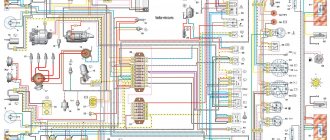
Currently, problems with a car’s electrical system can be corrected at any car service center, but for those who like to fix everything themselves, an electrical circuit will come in handy. The electrical diagram of a VAZ 21214 with an injection engine is a graphical representation that shows the order and connection of the elements in the circuit, but does not show the actual arrangement of the elements. But even the most inexperienced car enthusiast will be able to understand something in the electrical circuit of the VAZ 21214 and fix a small malfunction on his own, which will help save time and money.
1 – front lights; 2 – side direction indicators; 3 – headlight washer electric motor*; 4 – voltage regulator; 5 – battery charge warning lamp relay; 6 – battery; 7 – starter; 8 – generator; 9 – headlights; 10 – gearmotors for headlight cleaners*; 11 – sound signals; 12 – spark plugs; 13 – carburetor solenoid valve; 14 – ignition coil; 15 – windshield wiper gearmotor; 16 – coolant temperature indicator sensor; 17 – ignition distributor; 18 – windshield washer electric motor; 19 – oil pressure indicator sensor; 20 – oil pressure warning lamp sensor; 21 – brake fluid level warning lamp sensor; 22 – plug socket for a portable lamp; 23 – relay for turning on headlight cleaners and washer*; 24 – relay for turning on low beam headlights; 25 – relay for turning on the high beam headlights; 26 – windshield wiper relay; 27 – additional fuse block; 28 – main fuse block; 29 – additional resistor of the heater electric motor; 30 – reverse light switch; 31 – brake light switch; 32 – heater electric motor; 33 – relay-breaker for alarm and direction indicators; 34 – switch for the control lamp of the soyan brake; 35 – alarm switch**; 36 – cigarette lighter; 37 – switch for cleaners and headlight washers*; 38 – heater motor switch; 39 – external lighting switch; 40 – three-lever switch; 41 – ignition switch; 42 – instrument lighting switch; 43 – lamp switches located in the door pillars; 44 – interior lamps; 45 – oil pressure gauge with insufficient pressure warning lamp; 46 – fuel level indicator with reserve warning lamp; 47 – tachometer; 48 – parking brake warning lamp; 49 – battery charge indicator lamp; 50 – control lamp for the carburetor air damper; 51 – side light indicator lamp; 52 – turn signal indicator lamp; 53 – control lamp for high beam headlights; 54 – speedometer; 55 – switch for the carburetor air damper warning lamp; 56 – relay-interrupter for the parking brake warning lamp; 57 – coolant temperature indicator; 58 – brake fluid level warning lamp; 59 – differential lock warning lamp; 60 – switch for differential lock warning lamp; 61 – rear lights; 62 – license plate lights; 63 – sensor for level indicator and fuel reserve.
The order of conditional numbering of plugs in blocks:
a – windshield and headlight wipers, windshield wiper relay breaker; b – relay-breaker for alarm and direction indicators; c – three-lever switch; d – hazard warning switch.
* Installed on parts of manufactured cars; ** on cars produced in the 90s, due to the installation of breaker relays 33 without the fifth terminal, the brown wire connecting switch 35 to breaker relay 33 is missing.
Chevrolet Niva hub - replacement
To replace the wheel bearing in the field, you need to pull out the hub. This is carried out according to the following plan.
1. Dismounting the conical bushing.
2. Unlocking the nuts. The problem may lie in the fact that they often lick off or turn sour. In this case, you can use a chisel and a light hammer.
3. Use the nineteenth socket or wrench to remove the lever clamps. They are located both front and back.
4. The locking plates are removed. These are metal perforated strips that are often overlooked.
5. The seventeenth and tenth keys require removing the circuit pipes.
6. A stop is installed under the lever. Using two twelfths keys, unscrew the nut fixed on the upper arm retainer bolt.
7. The lower block is also unscrewed in the same way.
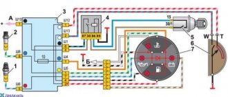
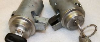
The structure of a car ignition switch
- Locking rod
- Frame
- Roller
- Contact disc
- Contact sleeve
- Block
- Protrusion of the contact part.
The lock mechanism is connected to many wires. They continue from the battery, connecting all the electrical devices of the car into a single chain. When you turn the ignition key, the electrical circuit is closed from the “-” terminal of the battery to the ignition coil. As a result, the current passes through the wires to the ignition switch, through its contacts it is directed to the induction coil, after which it returns back to the “+” terminal. As electricity passes through the coil, it generates high voltage, which it transmits to the spark plug. Therefore, the key closes the contacts of the ignition circuit, thereby starting the car engine.
bestruroad
Switch and ignition switch. Procedure for checking the carburetor valve control system of VAZ 2121 and 2131, electrical diagram. Diagnostics of electrical circuits of the Niva 2121 car.
I bought a new contact group, but the connection diagram for this Bulgarian lock is still interesting. Reg.: Messages: 759 From: Moscow, SAO Age: 44 Car: Lada 4×4 2131`2011&KiaRio JB`2009., 15:06. Messages: 3 From: r.p. Blagoveshchenka / Barnaul Age: 46 Car: VAZg., 4:51. Engeniator: For those who will be purchasing contact groups or a new lock, it makes sense to check the contact material with a magnet. I bought it on Friday. I took the so-called 'duplicate' for 330 rubles. The bad store asked 600 for the original. Well, all the external contacts are magnetic. :( I’m sitting in thought about whether to install the roofing felts or go and try to swear.
Ignition switch VAZ 21213 Connection diagram Photo relay
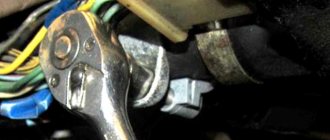
- At the moment the key is turned, the electrical circuit is closed from the “negative” terminal of the battery, as determined by the connection diagram for the VAZ 2106 ignition switch that comes to the coil. If the key begins to turn poorly or jams, this means that the secret is broken. Experts recommend spraying VD-40 into the larva, but the effectiveness of this is low and rather short-lived. Has the contact group burnt out, after which you have difficulty starting the starter? Change the ignition switch. The procedure for connecting wires to the ignition switch. Let's consider all stages of work one by one. First you need to remove the casing from the top. Salon of VAZ 2114 - tuning, photo.
- The ignition switch of the VAZ 2107 has a socket and it is more convenient to change the lock there. The permanent plus has pin 30/1 and 30, pin 50 goes to the starter and 1NT and 15 go to the devices, it turns out 30/1 +15 is the ignition 30+1NT is the devices and 30+50 is starter. Like Show list of likers. Kenshi Himura September 25, 2015 at 9:33 pm. Boris, VAZ 2101 connected everything according to the diagram, the starter does not start. Boris, Hello, can you please tell me that the VAZ 21213 Niva has a similar connection to the VAZ 2107? Like Show list of likers. Boris Aminov January 20, 2016 at 10:23 am. Neil, here's 21213. Like Show list of ratings. I’ll post what diagrams I have and a photo of the button and toggle switch. I did everything according to the third scheme. Help me please.
We carry out the adjustment ourselves
- The first step is to install the cylinder in the correct position. Installation is carried out so that the mark on the pulley is exactly at 0 degrees.
- Set how the slider is positioned. It should be aimed at the first pin in the cylinder.
- Use a strobe light and make sure the ignition is working properly.
- Make the electrical connections in the battery: minus to ground, plus to plus.
- The sensor must be connected to the high-voltage wire on the cylinder. The mark should connect to the crankshaft pulley.
- Start the engine at low speed (up to 800 rpm). Use a stroboscope to illuminate the pulley, and if the mark coincides with the middle mark, then the ignition is set correctly.
- Otherwise, the engine should be turned off and the meter should be loosened. In order to decrease the angle, turn the sensor clockwise; to increase it, turn it counterclockwise. Record and test the calibration again with the ignition on.
- Next, you should perform manipulations with the distribution sensor. Open the lid. Match the stator and rotor mark.
- Start the engine, bring the temperature to 75-80 degrees. When the speed is 50 km/h, sharply press the gas pedal.
- If the ignition was installed correctly, a short-term detonation will occur when you press the gas.
Also interesting: Phase sensor Niva Chevrolet symptoms of malfunction, DPRV high signal level
Then there are two possible developments: early and late ignition. Let's consider solutions for both cases:
- In the case of late ignition, when there is no detonation, you should change the position of the sensor clockwise.
- In the case of early ignition, when detonation lasts longer than necessary, the sensor is rotated counterclockwise.
Niva 21213 can be subject to adjustment of the starting system by the gap at the edges of the valves, if the carburetor is removed, or by the crankshaft speed directly on the car. In the first case, the gap at the location of the lower edge (in the direction of air movement) from the throttle valve is set to a width of 1.1 mm.
It is adjusted with a screw that has a 0.7 cm hexagon on the head and a slot from the shank. This operation is carried out with the cam lever turned counterclockwise from the starting system control (all the way). In the same position, the gap at the lower edge of the air damper is set to 3 mm using a screw in the cover from the diaphragm mechanism in the starting system (you need to loosen the lock nut).
The principle of powering a carburetor engine Adjusting the Niva starting system directly in the car saves time: You need to remove the air filter from the engine, pull the control lever towards you from the air damper, and start the engine. When the air damper is forced to open (by touching a flat screwdriver to a third of its full angle of rotation) using a screw (next to the lever on the axis from the throttle valve from the first chamber), the initial rotation speed is set to 2.08.mar.0 thousand.
revolutions per minute (on a warm engine). Remove the screwdriver, lower the air damper and, using the screw stop (next to the diaphragm), set the frequency to be 100 rpm lower than the original one (you need to select the appropriate position of the air damper). The screw can then be secured using a locknut.
If you have a gas analyzer, then the carburetor adjustment in the starting system part can be done based on the amount of CO (carbon monoxide) in the exhaust gases. If, with the choke control lever fully extended, the gas rate is 8%, then everything is in order. If there is less gas than this value, then the screw on the cover of the diaphragm mechanism is tightened; if there is more, it is unscrewed and repeated measurements are taken.
It is necessary to adjust the idle speed of the Niva 2121 so that there is less carbon monoxide in the exhaust gases and so that the engine runs stably. At service stations, such work is carried out with gas analyzers on the MV. In the garage, adjustments can be made using the tachometer.
Adjusting the device For these purposes, on a warm engine, pierce the plastic plug with a screwdriver, then the quality screw is rotated in different directions until the maximum idle speed is reached. Then, using the quantity screw (has a ribbed plastic handle), you need to set an increased speed (50-70 rpm.
Possible malfunctions if the starter does not turn
| See all advertisements in the archive |
| Possible malfunction | Diagnostics | Solution |
| Battery is discharged | The starter clicks but does not turn. The voltage at the battery terminals with consumers turned on is less than 12 V | Charge or replace the battery |
| Oxidation of battery terminals or poor connection | The starter clicks but does not turn. When the starter is turned on, the voltage at its terminals drops much more than at the battery terminals | Clean the contacts, lubricate with Vaseline and tighten well |
| There are problems in the wiring of the starter traction (retractor) relay, ignition contacts 30 and 50 do not close. | When turning the key there is no click under the hood (the relay does not work). Check the presence of voltage at the control contact of the solenoid relay | Clean the contacts, lubricate with Vaseline and tighten well. Replace the ignition switch |
| The starter solenoid relay is faulty. | When you turn the key, there is no click under the hood (the relay does not work), but there is +12 V at the control contact of the solenoid relay. The starter spins when closed with a screwdriver. The starter does not turn only when it is hot (when the engine is warm) | Replace starter relay |
| Solenoid relay contacts are oxidized, poor ground contact | When you turn the key there is a click under the hood, but the starter does not turn. Using an ohmmeter, check the resistance of the “battery - starter” circuit, as well as the ground wire. If the circuits are OK, remove the starter and check the operation of its relay | Clean the contacts, lubricate with Vaseline and tighten well. Replace the solenoid relay |
| Open or short circuit in the holding coil of the solenoid relay | When the starter is turned on, a cracking noise is heard from under the hood. The battery voltage is within normal limits. The relay is checked with an ohmmeter or by its excessive heating | Replace starter relay |
| Burnt starter commutator, stuck brushes or severe wear | The starter does not turn or turns slowly. With the starter removed, check the pressing force of the brushes to the commutator, their residual height, and wear of the commutator | Repair the starter. If the commutator is very worn, replace the starter. |
| Open or short circuit in the starter armature winding | The starter does not turn or turns slowly. The serviceability of the winding is checked with an ohmmeter or by darkening of the insulation | Replace starter |
| Freewheel slipping | The starter spins, but the flywheel is stationary | Replace clutch or starter |
| The ring gear rotates on the flywheel | The starter spins, but the flywheel and crankshaft are stationary. There is a squeal, a howl from the clutch housing | Replace flywheel |
| The engine or attachments are jammed | Check the rotation of the crankshaft, alternator pulleys, coolant pump and power steering pump | Repair the engine or its attachments |
| The starter drive gear or flywheel ring teeth are damaged | Visual inspection after removing the starter | Repair or replace starter, replace flywheel |
Have you encountered the problem of starting the engine when the starter does not turn? What was the cause of your problem? Let us remind you that other instructions for repair and operation of Lada 4×4 can be found in this category or by content.
Features of the modification
First of all, the changes affected the engine management system and control instruments. In particular:
- The wiring diagram for Niva 21213 received an additional wiring harness in the engine compartment for connecting a microcontroller and sensors;
- On the Niva model of recent years of production, a more advanced power unit with the VAZ-21214 index is installed. Instead of a carburetor, it has a fuel frame with injectors from GM. The price of a car with injection has increased because of this;
- The instrument panel has changed - the design is borrowed from the VAZ 2108 model.
Ignition system
The VAZ 21213 engine uses a non-contact ignition system consisting of:
- ignition distributor sensor (marking 3810.3706). It is responsible for creating control pulses supplied to the electronic switch;
- switch (model marking – 3620.3734) in climatic version U2.1 (corresponds to GOST 15150);
- ignition coils (marking 27.3705).
For reference: this device provides increased spark energy, which helps start the engine in cold weather, and also improves the performance of the power unit when operating the vehicle on low-quality fuel.
Dashboard
A modified instrument panel appeared on the car. In particular, instead of a voltmeter, the manufacturer installed a low battery discharge lamp (no. 12 in the diagram).
Tip: if you often operate your car in off-road conditions, you can buy and connect a voltmeter to the instrument panel yourself. It is more informative than a warning light and will allow you to identify electrical system faults long before the battery discharges.