3.9/5 — (65 votes)
The article will describe the pinout of the VAZ 2114 ECU and discuss all the modifications and features of this device. As you understand, any modern car is a whole arsenal of sensors and mechanisms. And they allow you to squeeze maximum power out of the engine without changing its volume. In order to independently repair electronics or carry out firmware, you need to know what a control unit is and on what principles it operates.
Car modifications 2114
VAZ-21140 . Modification with an 8-valve injection engine VAZ-2111, 1.5 liters and 77 horsepower. Serial production from 2003 to 2007
VAZ-21144 . Modification with an 8-valve VAZ-21114 engine, 1.6 liters and 81.6 horsepower. Years of serial production: 2007-2013.
VAZ-211440 . Another modification released in 2007, it was equipped with a VAZ-11183 engine with a volume of 1.6 liters and a power of 82 horsepower. The car was discontinued in 2013.
VAZ-211440-24 . Released in 2009, a modification with an injection 16-valve VAZ-21124 engine with a volume of 1.6 liters and a power of 89.1 horsepower. Discontinued in 2013.
VAZ-211440-26 . Modification with a 16-valve injection engine VAZ-21126, which complies with the Euro-3 environmental standard, with a volume of 1.6 liters and a power of 98 hp. The car was produced from 2010 to 2013.
Search this blog
Firmware and modification of Bosch ME7.9.7, Bosch M797(+), Kefico units
The control unit supports the following commands for reprog: Establish communication Read / Write FLASH Read / Write EEPROM / ECU passport (Bosch M797 and M797+ ECU only)
Attention! All operations during reprogramming are performed with the unit, which is switched to programming mode, after the “Establish communication” operation is performed, which is necessary to transfer the control unit from diagnostic mode to reprogramming mode.
To program the ECU on the table, it is necessary to modify the unit, which will be discussed below. Firmware file size for FLASH memory:
Bosch M797 – 512 KB (524288 bytes), EEPROM memory – 512 bytes. Bosch M797+ – 832 KB (851968 bytes), EEPROM memory – 512 bytes.
Due to the fact that the Kefico ECUs installed on KIA / HYUNDAI cars, as well as the M797 ECUs on Chery Amulet, Geely cars are schematically very similar to the Bosch M797, reprogramming these control units is similar to reprogramming the Bosch M797 ECU.
Wiring diagram VAZ-2114 for old models
Electrical diagram of car 2114: 1 - headlight; 2 [Installed on a part of the car] - fog lamp; 3 — ambient air temperature sensor; 4 — electric engine radiator fan; 5 — block for connection to the wiring harness of the engine control system; 6 — engine compartment lamp switch; 7 [Installed on a part of the car] - reserve block for connecting an audio signal with one terminal (the negative terminal is connected to the body); 8 — sound signal; 9 — liquid level sensor in the windshield washer reservoir; 10 [Installed on a part of the car] - brake pad wear sensor; 11 — low oil level sensor; 12 - generator; 13 [Installed on a part of the car] - engine compartment lamp; 14 — temperature indicator sensor; 15 — starter; 16 — battery; 17 [Installed on a part of the car] - relay for turning on fog lights; 18 — coolant level sensor in the expansion tank; 19 — sensor of insufficient brake fluid level; 20 — reversing light switch; 21 — windshield wiper gear motor; 22 — emergency oil pressure sensor; 23 — rear window washer electric pump; 24 — electric pump for windshield washer; 25 — instrument panel; 26 — mounting block of fuses and relays; 27 — brake signal switch; 28 — ignition relay; 29 - ignition switch (lock); 30 — glove box lighting lamp; 31 — switch for the glove compartment lighting lamp; 32 — rear window heating switch; 33 — rear fog light switch; 34 [Installed on a part of the car] - fog light switch; 35 - combined switch for side lights and headlights; 36 — alarm switch; 37 — steering column switches; 38 — brightness control for instrument lighting; 39 — illumination lamp for the headlight hydraulic adjustment control handle; 40 — socket for connecting a portable lamp; 41 — side direction indicator; 42 — interior lighting switch (front door open sensor); 43 — interior lamp; 44 — electric fan of the ventilation and heating system; 45 — additional resistor of the electric fan of the ventilation and heating system; 46 — switch for operating modes of the electric fan of the ventilation and heating system; 47 — illumination lamp for the handle of the operating mode switch of the electric fan of the ventilation and heating system; 48 — backlight lamp for the heater control unit; 49 — display unit of the on-board control system; 50 [Installed on part of the car] - trip computer; 51 — interior lighting switch (rear door open sensor); 52 [Installed on a part of the car] - block for connecting a clock; 53 — fuel module; 54 — ashtray illumination lamp; 55 — cigarette lighter; 56 — interior lamp; 57 — switch for the parking brake warning lamp; 58 — rear light; 59 — license plate light; 60 — additional brake light; 61 — heating element for heating the rear window; 62 — rear window wiper gear motor; A - numbers of pins in connecting blocks.
ECU BOSCH 21114-1411020-30 M 7.9.7+.
Dear customers, in order to avoid errors when sending an electronic engine control unit (ECU, ECM, controller), indicate your car model, year of manufacture and number of valves in the “Comment” line.
The Electronic Engine Control Unit (ECU) is the “computer” that controls the entire vehicle system. The ECU affects both the operation of an individual sensor and the entire vehicle. Therefore, the electronic engine control unit is very important in a modern car.
The controller firmware in the photo and availability in the warehouse may differ. When ordering, please specify the required firmware.
The following firmware versions are available:
Bosch controllers 21114-1411020-30 M7.9.7 and M7.9.7+
| Software ID | ECU | VAZ number | Engine | Toxic standards | Note |
| Bosch M7.9.7 | |||||
| B104DN15 | Bosch M7.9.7 | 21114-1411020-30 | 21114 | E-2 | 1 Serial version 1.6 Attention! "Glitchy" software. |
| B104DP16 | Bosch M7.9.7 | 21114-1411020-30 | 21114 | E-2 | 2 Serial version 1.6 |
Bosch M7.9.7 new hardware implementation (M7.9.7+)
| B104DQ17 | Bosch M7.9.7+ | 21114-1411020-30 | 21114 | E-2 | 1 Serial version for new hardware implementation |
| B104DR17 | Bosch M7.9.7+ | 21114-1411020-30 | 21114 | E-2 | 2 Serial version for new hardware implementation |
Product features: Electronic engine control unit (catalog designation “BOSCH”, 0 261 207 827, Motronic 1126 6716 B104DR17 France), using various signals from engine sensors, controls the composition and amount of fuel supplied to the engine.
INFORMATION LETTER No. 14-2005-I
Interchangeable controllers: January 7.2. 21114-1411020-32 Euro – 2, January 7.2. 21114-1411020-31 Euro – 2 .
VAZ 2113-2115 after 2006, VAZ-21101; VAZ-21104 their modifications.
Varieties of electronic engine control systems (ECM, controllers), which are installed on different models of the VAZ family car.
How does a malfunction of the electronic engine control unit (ECU, ECM, controller) manifest itself in a VAZ family car.
How to independently replace the electronic engine control unit (ECU, ECM, controller) on a VAZ family car.
With the AvtoAzbuka online store, repair costs will be minimal.
Don't forget to share the information you find with your friends and acquaintances, because they may also need it - just click one of the social networking buttons located above.
VAZ-2114 diagram (second option)
Electrical diagram of VAZ-2114 cars (without engine control system):
1 — block headlights; 2 — fog lights; 3 — air temperature sensor; 4 — electric motor of the engine cooling system fan; 5 — blocks connected to the wiring harness of the ignition system; 6 — engine compartment lamp switch; 7 — block for connecting to a single-wire type audio signal; 8 — sound signal; 9 — washer fluid level sensor; 10 — front brake pad wear sensor; 11 — oil level sensor; 12 - generator; 13 — engine compartment lamp; 14 — coolant temperature indicator sensor; 15 — starter; 16 - battery; 17 — relay for turning on fog lights; 18 — coolant level sensor; 19 — brake fluid level sensor; 20 — reverse light switch; 21 — windshield wiper gearmotor; 22 — oil pressure warning lamp sensor; 23 — block for connecting to the rear window washer electric motor; 24 — electric motor for windshield washer; 25 — instrument cluster; 26 — mounting block 2114; 27 — brake light switch; 28 — ignition relay; 29 — ignition switch; 30 — glove box lighting lamp; 31 — glove box lighting switch; 32 — rear window heating element switch; 33 — rear fog light switch; 34 — fog lamp switch; 35 — switch for external lighting lamps; 36 — alarm switch; 37 — steering column switches; 38 — switch for instrument lighting lamps; 39 — lamp for illuminating the headlight hydrocorrector scale; 40 — plug socket for a portable lamp; 41 — side direction indicators; 42 — lamp switch on the front door pillars; 43 — lamp for individual interior lighting; 44 — heater fan electric motor; 45 — additional resistor of the heater electric motor; 46 — heater fan switch; 47 — heater switch illumination lamp; 48 — lamp for illuminating the heater levers; 49 — on-board control system unit; 50 — trip computer; 51 — lamp switch on the rear door pillars; 52 — block for connecting the wiring harness of the engine control system; 53 — electric fuel pump and gasoline quantity sensor; 54 — front ashtray illumination lamp; 55 — cigarette lighter 2114; 56 — trunk lighting lamp; 57 — trunk light switch; 58 — interior lamp; 59 — parking brake warning lamp switch; 60 — rear external lights; 61 — rear internal lights; 62 — block for connection to the rear window heating element; 63 — license plate lights; 64 - additional brake signal located in the spoiler.
Conventional numbering of plugs in blocks:
- A — headlight blocks;
- B — electric fuel pump block;
- C — blocks of the mounting block, ignition switch, windshield wiper gearmotor;
- D — blocks for the interior lamp.
ECU January7.2
Pins 1, 4, 9, 11, 21-26, 28-30, 41-43, 49, 52, 54-56, 58, 60, 62, 72-74, 77, 78, 81 are not used.
The purpose of the rest is as follows:
- 2, 5 – control of the ignition coils of cylinders 2, 3 and 1, 4.
- 3 – ignition mass.
- 6, 7, 27, 47 – control of injectors of cylinders 2, 3 and 1, 4.
- 8 – tachometer connection.
- 10 – fuel consumption value.
- 12 – voltage from the battery.
- 13 – voltage from the ignition switch.
- 14 – turn on the main relay.
- 15 – contact A DPKV.
- 16, 17, 32 – signal, ground and supply voltage of the TPS.
- 18 – oxygen sensor (OS).
- 19, 20 – Power supply and mass of the knock sensor (DS).
- 31 – Check Engine indicator.
- 34 – contact B DPKV.
- 35, 39 – ground and signal wire DTOZH.
- 33, 36, 37 – power supply, ground and signal wire of the mass flow sensor.
- 40 – intake temperature control.
- 44, 63 – main relay, output voltage.
- 45 – supply voltage to DF.
- 46 – adsorber, purge valve.
- 48 – DC heater.
- 50 – activation of the starter relay.
- 51, 53 – controller mass.
- 57 – selection of calibration data options.
- 59 – speed sensor.
- 61 – mass
- 64, 65, 66, 67 – idle air control (IAC) contacts D, C, B, A.
- 68 – fan.
- 69 – air conditioner.
- 70 – electric fuel pump.
- 71 – K-line.
- 75 – air conditioner.
- 76 – power steering.
- 79 – DF.
- 80 – general.
The pinout of the M73 Itelma ECU on the VAZ 2114 is similar to that shown above. The differences between the controllers are only in the software.
Wiring diagram VAZ-2114 new models
The updated engine has a new injection scheme, so it was necessary to use some new devices, as well as replace the ignition coil with a more efficient one and adapted to Euro 3 conditions. In order to comply with them, the engine had to minimize the amount of CO at start-up. And for this it was necessary to lean the mixture. Since a lean mixture ignites worse, it needed a more powerful spark to spark. This explains the use of a coil of increased power.
- block headlights;
- gearmotors for headlight cleaners*;
- fog lights*;
- ambient temperature sensor;
- sound signals;
- engine compartment light switch;
- engine cooling fan electric motor;
- generator VAZ-2114;
- low oil level indicator sensor;
- washer fluid level sensor;
- front brake pad wear sensor;
- wire ends connected to the common windshield washer pump**;
- windshield washer pump;
- headlight washer pump*;
- wire ends for connecting to the rear window washer pump on VAZ-2113 and VAZ-2114 cars;
- low oil pressure indicator sensor;
- engine compartment lamp;
- wire lug for connecting to the engine management system wiring harness;
- windshield wiper gear motor;
- starter VAZ-2114;
- block connected to the wiring harness of the ignition system on carburetor cars;
- coolant temperature indicator sensor;
- reverse light switch;
- low brake fluid level indicator sensor;
- accumulator battery;
- low coolant level indicator sensor;
- relay for turning on fog lights;
- mounting block;
- brake light switch;
- plug socket for a portable lamp;
- hydrocorrector scale illumination lamp;
- parking brake indicator lamp switch;
- block for connecting a backlight lamp;
- switch for instrument lighting lamps;
- Understeering's shifter;
- hazard switch;
- front seat heating element relay;
- ignition switch;
- rear fog lamp circuit fuse;
- front seat heating elements circuit fuse;
- door lock circuit fuse;
- front ashtray illumination lamp;
- ignition relay;
- cigarette lighter VAZ-2114;
- glove box lighting lamp;
- glove compartment light switch;
- heater fan motor;
- additional heater motor resistor;
- heater fan switch;
- heater switch illumination lamp;
- heater lever illumination lamp;
- gear motors for electric windows of the front doors;
- right front door ESP switch (located in the right door);
- gear motors for locking front door locks;
- wires for connecting to the right front speaker;
- gear motors for locking rear doors;
- wires for connecting to the right rear speaker;
- door lock control unit;
- wires for connecting to radio equipment;
- headlight wiper switch*;
- rear window heating element switch;
- rear fog light relay;
- block for connection to the heating element of the right front seat;
- rear fog light switch;
- right front seat heating element switch;
- fog light switch*;
- switch for external lighting lamps;
- left front seat heating element switch;
- block for connection to the heating element of the left front seat;
- wires for connecting to the left front speaker;
- left front door power window switch (located in the left door);
- right front door power window switch (located in the left door);
- wires for connecting to the left rear speaker;
- side direction indicators;
- dome light switches on the front door pillars;
- dome light switches on the rear door pillars;
- lampshade VAZ 2114;
- individual interior lighting lamp;
- block for connecting to the wiring harness of the electric fuel pump;
- trunk light switch;
- instrument cluster;
- trunk light;
- on-board control system display unit;
- trip computer*;
- block for connecting the wiring harness of the engine management system;
- rear exterior lights;
- rear interior lights;
- pads for connecting to the rear window heating element;
- license plate lights;
- additional brake signal located on the spoiler.
Numbering order of plugs in blocks:
A - headlight units and headlight cleaners; B - cigarette lighter; B - mounting block, instrument cluster, ignition switch, windshield wiper and other electrical components (for blocks with a different number of plugs, the numbering order is similar); G — relay for turning on the rear fog light; D — alarm switch; E — electric window motors and door lock motors; F — interior lamp.
In the instrument panel wiring harness, the second ends of the white wires are brought together into one point, which is connected to the instrument lighting switch (except for the white wire, from plug “4” of block “X2” of mounting block 28 to display block 83 of the on-board control system). The second ends of the black wires are also brought together to points connected to ground. The second ends of the yellow wires with a blue stripe are brought together to a point connected to plug “4” of the “X1” block of the mounting block. The second ends of the white wires with a red stripe are brought together to a point connected to plug “10” of the “X4” block of the mounting block. The second ends of the orange wires are brought together to a point connected to plug “3” of the “X4” block of the mounting block.
Explanations for the 8-pin injector block: white-red and blue - for the check light bulb, blue-red - ignition, gray - speed sensor, brown-red - tachometer, blue-white - driver's door switch (for the immobilizer), green- red - K-line (may not exist), green - fuel consumption. Next to it is a pink wire - to the fuel level sensor.
ECU January-4
The January 4 electronic control unit has three connectors, which differ in color and number of contacts. The pinout is as follows:
Pink connector 24 pins:
- A1-A4 – common wire of the on-board network (ground);
- A8, A9 – ignition coil of cylinders 2, 3 and 1, 4;
- A11 – +5V output for powering sensors;
- A12, B8 – positive pole of the battery;
- B2 – tachometer signal;
- B3 – air conditioner clutch;
- B4 – speed signal;
- B5 – adsorber, purge valve control;
- B6 – mass air flow sensor;
- B7 – coolant temperature;
Pink connector 32 pins:
- C1 – positive voltage 12 V from the ignition switch;
- C2 – DD;
- C3 – fuel pump;
- C5 – L-line;
- C12, D8 – control of turning on the injectors of cylinders 2, 3 and 1, 4;
- C16, D16 – mass and signal of the λ-probe (oxygen sensor);
- D10 – air conditioner;
- D16 – DC;
- Blue connector 32 pins:
- C2 – fuel consumption;
- C5, C6 – idle, high and low levels A;
- C7, C8 – idle, high and low levels B;
- C9 – speed sensor;
- C12 – coolant mass;
- C16, D16 – DPKV. High and low levels;
- D1, D12 – TPS signal and mass;
- D2 – fan;
- D4 – k-Line;
- D5 – Check Engine indicator;
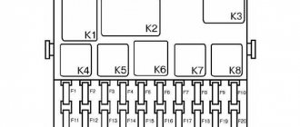
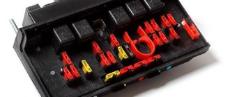
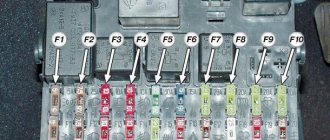
Relays and fuses VAZ 2114
F1 for 10 Amps (A) rear fog lights and rear fog light warning lamp. F2 for 10 A turn signal lamps, turn signal relay, hazard lights, hazard warning lights. F3 7.5 A lamps for interior lighting (both) and trunk, ignition lighting, powertrain control system control lamp, brake lamps, computer, if available. F4 20 A carrier, relay and rear window heating element. F5 20 A horn and its relay, cooling fan. F6 30 A power windows and their relays F7 30 A motor heater, headlight cleaner, windshield washer, cigarette lighter, glove compartment light bulb, rear window heating relay winding. F8 7.5 A right fog lamp. F9 7.5 A left fog lamp. F10 at 7.5 A left side marker, lamp signaling the inclusion of the side light, lamps for illuminating the sign, engine compartment, illumination of switches and instruments, instrument lighting switch. F11 at 7.5 A right side. F12 at 7.5 A right low beam. F13 at 7.5 A left low beam. F14 for 7.5 A left high beam and a light indicating that the high beam headlights are on. F15 at 7.5 A right far. F16 30 A - a light indicating insufficient oil pressure, brake fluid level, engagement of the parking brake, low battery, instrument cluster, relay for monitoring the health of lamps, indication of control systems, reversing lamps, turn indicators and their relays, as well as an alarm if turning mode is turned on, computer, generator excitation winding is turned on at the moment the engine starts.
Generalized ECU pinout
January-5.x:
- ECU pin 19 - Ground
- ECU pin 55 - K-Line
- ECU pin 27 - Turn on the ignition (+12V)
- ECU pin 18 - Non-switchable power supply (+12V)
- ECU pin 47 - Programming permission (+12V through a resistor of about 4KOhm)
- ECU pin 37 - Power from the main relay (+12V)
VS-5.1:
- ECU pin 19 - Ground
- ECU pin 55 - K-Line
- ECU pin 27 - Turn on the ignition (+12V)
- ECU pin 18 - Non-switchable power supply (+12V)
- ECU pin 47 - Programming permission (+12V through a resistor of about 4KOhm)
- ECU pin 37 - Power from the main relay (+12V)
Mikas-7.1:
- ECU pin 19 - Ground
- ECU pin 55 - K-Line
- ECU pin 27 - Turn on the ignition (+12V)
- ECU pin 18 - Non-switchable power supply (+12V)
- ECU pin 42 - Programming permission (+12V through a resistor of about 4KOhm)
- ECU pin 37 - Power from the main relay (+12V)
Mikas-7.6:
- ECU pin 19 - Ground
- ECU pin 55 - K-Line
- ECU pin 27 - Turn on the ignition (+12V)
- ECU pin 18 - Non-switchable power supply (+12V)
- ECU pin 47 - Programming permission (+12V through a resistor of about 4KOhm)
- ECU pin 37 - Main relay power supply (+12V)
Bosch MP-70:
- ECU pin 19 - Ground
- ECU pin 55 - K-Line
- ECU pin 27 - Turn on the ignition (+12V)
- ECU pin 18 - Non-switchable power supply (+12V)
- ECU pin 50 - Programming permission (+12V through a resistor of about 4KOhm) - must be applied only when writing FullFlash or calibration area. Reading - in the “diagnostics on the table” mode.
- ECU pin 37 - Main relay power supply (+12V)
Bosch 7.9.7:
- 51.53 ECU contact - Ground
- 71 ECU contacts - K-Line
- ECU pin 13 - Turn on the ignition (+12V)
- ECU pin 12 - Non-switchable power supply (+12V)
- ECU pin 43 - Programming permission (Ground)
- 44.63 ECU contact - Main relay power supply (+12V)
January 7.2:
- 51.53 ECU contact - Ground
- 71 ECU contacts - K-Line
- ECU pin 13 - Turn on the ignition (+12V)
- ECU pin 12 - Non-switchable power supply (+12V)
- ECU pin 43 - Programming permission (+12V, through a resistor of about 4KOhm)
- 44.63 ECU contact - Main relay power supply (+12V)
January 7.2+:
- 51.53 ECU contact - Ground
- 71 ECU contacts - K-Line
- ECU pin 13 - Turn on the ignition (+12V)
- ECU pin 12 - Non-switchable power supply (+12V)
- 44.63 ECU contact - Main relay power supply (+12V)
Mikas 10.3:
- 51.53 ECU contact - Ground
- 71 ECU contacts - K-Line
- ECU pin 13 - Turn on the ignition (+12V)
- ECU pin 12 - Non-switchable power supply (+12V)
- ECU pin 43 - Programming permission (+12V)
- 44.63 ECU contact - Main relay power supply (+12V)
Mikas 11 (GAZ cars):
- 51.53 ECU contact - Ground
- 71 ECU contacts - K-Line
- ECU pin 13 - Turn on the ignition (+12V)
- ECU pin 12 - Non-switchable power supply (+12V)
- 44.63 ECU contact - Main relay power supply (+12V)
Mikas 10.3+ (Mikas-11):
- 51.53 ECU contact - Ground
- 71 ECU contacts - K-Line
- ECU pin 13 - Turn on the ignition (+12V)
- ECU pin 12 - Non-switchable power supply (+12V)
- 44.63 ECU contact - Main relay power supply (+12V)
Siemens 5WY SIMK31 (2 connectors, Chery QQ cars):
- 1, 2 - ECU weight
- 21 - main relay power supply +12V
- 22 - switchable power supply +12V (ignition switch)
- 44, 63 - non-switchable power supply +12V (battery)
- 77 – K-Line
Bosch ME 7.9.9 (Chevrolet Captiva):
- 1,2,67,68 - ECU ground (any of the indicated contacts can be used)
- 18 - non-switchable power supply +12V (battery)
- 39 — switchable +12V power supply (ignition switch)
- 38 – K-Line
Bosch MG 7.9.8 (cars with automatic transmission):
- Connector A (small)
- 11, 56 - +12V
- 59 - K-Line, engine Connector B (large)
- 1, 2, 3 - ECU ground (just connect any of the indicated contacts)
- 84 K-Line, automatic transmission The appropriate K-Line must be connected depending on what operations need to be performed (with the automatic transmission or engine processor).
Siemens SIMK31:
- 1, 2 - ECU weight
- 21 - main relay power supply +12V
- 22 - switchable power supply +12V (ignition switch)
- 44, 63 - non-switchable power supply +12V (battery)
- 77 – K-Line
Siemens SIM2K-47 (boot mode):
- Connector B (large)
- 1, 3, 5 - ECU ground (it is enough to use any of the contacts)
- 2, 4, 6 — +12V
- 75 – K-Line
Views: 22
Engine management system
VAZ-2111 engine with distributed fuel injection to R83-02 toxicity standards with controller 2111-1411020-61 (January-5.1) or 2111-1411020-60 (M1.5.4N) on VAZ-2113, -2114, -2115 vehicles
| 1 – fragment of the mounting block; 2 – electric fan of the engine cooling system; 3 – status indicator of the car anti-theft system; 4 – control unit of the automobile anti-theft system; 5 – coolant temperature sensor; 6 – air flow sensor; 7 – throttle pipe; 8 – block connected to the throttle position sensor; 9 – block connected to the idle speed regulator; 10 – controller; 11 – block connected to the air conditioner wiring harness; 12 – oxygen sensor; 13 – knock sensor; 14 – crankshaft position sensor; 15 – speed sensor; 16 – adsorber; 17 – battery; 18 – main relay; 19 – block connected to the wiring harness of the anti-lock brake system; 20 – diagnostic block; 21 – fuse for protecting the main relay circuits; 22 – controller protection fuse; 23 – fuse for protecting the electric fuel pump and its relay; 24 – relay for turning on the electric fuel pump; 25 – relay for turning on the electric fan; 26, 27 – blocks connected to the instrument panel wiring harness; | 28 – ignition module; 29 – electric fuel pump with fuel level sensor; 30 – spark plugs; 31 – nozzles; F – front harness wire going to the “B+” terminal of the generator; G – wires of the front wiring harness. The order of conditional numbering of plugs in the blocks: A – controller; B – control unit of the automobile anti-theft system; B – indicator of the state of the automobile anti-theft system; G – pads 26; D – throttle pipe; E – air flow sensor; F – electric fuel pump and oxygen sensor; Z – speed sensor; And – ignition module. Purpose of the plugs in block 26 : 1 – to the low-voltage input of the tachometer in the instrument cluster; 3 – to the engine management system control lamp in the instrument cluster (from the controller); 4 – to the lamp switch located on the driver’s door pillar; 5 – to the control lamp of the engine management system in the instrument cluster (supply “+” power); 6 – to the trip computer (fuel consumption signal); 7 – to the instrument cluster (vehicle speed signal); 8 – to terminal “15” of the ignition switch (plug 4 of the switch block). |
VAZ-2111 engine with distributed fuel injection to Euro-2 emission standards with controller 2111-1411020-40 (MP7.0) on VAZ-2113, -2114, -2115 vehicles
| 1 – fragment of the mounting block; 2 – electric fan of the engine cooling system; 3 – status indicator of the car anti-theft system; 4 – control unit of the automobile anti-theft system; 5 – coolant temperature sensor; 6 – air flow sensor; 7 – throttle pipe; 8 – block connected to the throttle position sensor; 9 – block connected to the idle speed regulator; 10 – controller; 11 – block connected to the air conditioner wiring harness; 12 – oxygen sensor; 13 – knock sensor; 14 – crankshaft position sensor; 15 – speed sensor; 16 – adsorber; 17 – battery; 18 – main relay; 19 – block connected to the wiring harness of the anti-lock brake system; 20 – diagnostic block; 21 – fuse for protecting the main relay circuits; 22 – controller protection fuse; 23 – fuse for protecting the electric fuel pump and its relay; 24 – relay for turning on the electric fuel pump; 25 – relay for turning on the electric fan; 26, 27 – blocks connected to the instrument panel wiring harness; 28 – ignition module; 29 – electric fuel pump with fuel level sensor; | 30 – spark plugs; 31 – nozzles; F – front harness wire going to the “B+” terminal of the generator; G – wires of the front wiring harness. |
The order of conditional numbering of plugs in blocks:
A – controller; B – control unit of the automobile anti-theft system; B – indicator of the state of the automobile anti-theft system; G – pads 26; D – throttle pipe; E – air flow sensor; F – electric fuel pump and oxygen sensor; Z – speed sensor; And – ignition module.
Purpose of plugs in block 26:
1 – to the low-voltage input of the tachometer in the instrument cluster; 3 – to the engine management system control lamp in the instrument cluster (from the controller); 4 – to the lamp switch located on the driver’s door pillar; 5 – to the control lamp of the engine management system in the instrument cluster (supply “+” power); 6 – to the trip computer (fuel consumption signal); 7 – to the instrument cluster (vehicle speed signal); 8 – to terminal “15” of the ignition switch (plug 4 of the switch block).
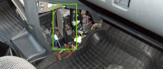
Repair and diagnostics of control units
The VAZ 2114 controller often breaks down. The system has a self-diagnosis function - the ECU queries all components and issues a conclusion about their suitability for operation. If any element fails, the “Check Engine” lamp will light up on the dashboard. It is possible to find out which sensor or actuator has failed only with the help of special diagnostic equipment. Even with the help of the famous OBD-Scan ELM-327, loved by many for its ease of use, you can read all engine operating parameters, find the error, eliminate it and delete it from the memory of the VAZ 2114 ECU.
Of course, it is wrong to simply delete errors. Be careful, because malfunctions don’t just appear. A good example is that a friend’s oxygen sensor broke down. And every other day he cuts down the mistake so that “it doesn’t become an eyesore.” But the reason lies in a faulty lambda. But what to do if the ECU does not want to respond to the scanner at all? Then check the following:
- Is there any mechanical damage to the housing, including oxidation and corrosion?
- The fuse is working properly, there is voltage and a connection to the power supply minus.
- Is the device overheating?
Deciphering the factory markings of VAZ firmware
The software of modern ECUs is marked by the manufacturer with an alphanumeric code, divided into 5 groups.
the first group – letter and number indicates the type (family) of the controller: J4 – control units (ECU) January‑4/4.1; J5 – control units January‑5.1/5.1.1/5.1.2; V5 – control units VS‑5.1 (NPO Itelma); M1 – Motronic control units M1.5.4 (M1.5.4N); N (New) – new hardware implementation of M7 – Motronik MP7 control units.
V – VAZ cars with front-wheel drive of the 2108, 2110 families; N – family of cars with all-wheel drive VAZ;
For some reason, the exception was firmware for classics, for example, J5V26L52, etc.
third group - two digits indicate the conditional configuration number (00...99); For front-wheel drive VAZ cars, the following numbers exist:
03 – Euro-2 toxicity standards, 8-valve 1.5L engine; 05 – Euro-2 toxicity standards, 16-valve 1.5L engine; 07 – Russian standards, 16-valve 1.5L engine; 13 – Russian standards, 8-valve 1.5L engine. 26 – Russian standards, 8-valve 1.45L engine. Rear-wheel drive (classic). the fourth group - letter, indicates the ordinal software level (A...Z), the further the letter in the alphabet, the newer the software level;
the fifth group – two digits, indicates the calibration version (00...99), the larger the number, the newer the calibration.
ECU Bosch M7.9.7, M10, January 7.2/7.2+
The first group in them is one letter - the manufacturer’s code
I – ItelmaB – BoschА – Avtel
second group – one digit – controller model
1 – M10 1 – M7.9.72 – January 7.2
third group - 3 characters (numeric-alphabetic code) - symbol of the project according to the internal VAZ classification.
03E - project 2111, Euro II18E - project 2111, Euro III04D - project 21114, Euro II18D - project 21114, Euro III05D - project 21124, Euro II08D - project 21124, Euro III20E - project 21214, Euro II21E - project 21214, Euro III22H - project 21214, Euro III01C - project 11183, Euro II C02 - project 11183, Euro III02C - project 11183, Euro III73C - project 11184, Euro III73D - project 21126, Euro III C02 - project 11183, Euro III26F - project 21067, Euro II26E - project 21067, Euro II
fourth group – 1 letter – software version.
fifth group – 2 digits – calibration number
Example:
B103EQ09 – Bosch, М7.9.7, project 03E, software version – “Q”, calibration number 09I203EK34 – Itelma, January 7, project 03E, software version – “K”, calibration number 34
An attempt to classify tuning firmware designations
Since there is clearly a need to systematize firmware with changed calibrations, in the designation of firmware we will adhere to the following rules: calibrations of front-wheel drive VAZs - “V”, replaced by:
A” – for firmware for non-standard “hardware” “B” – “Butan” – firmware for operation on liquefied gas “C” – “Cam” – firmware for non-standard camshafts “D” – “Dynamic” – for dynamic firmware “E” – “Economy” – for economical firmware “M” – “Modify” – modified firmware “T” – “Tuning” – tuned firmware
What kind of ECUs are installed on the VAZ 2110
Earlier I already talked about what kind of ECUs are installed on the VAZ 2114, if you are interested, read this article! So, dozens of electronic control units are installed with similar ones.
January 4 – technical specifications for which VAZ 2110 models are installed
One of the most common ECUs installed on the VAZ 2110 is January 4.
Structural management system January 4
January 4 was installed on the first generation VAZ 2110 model of 1999. Of course, this is not the most advanced ECU for a VAZ, but it still has a number of advantages, which I will talk about later.
Bosch M1.5.4 - advantages and disadvantages of use in the VAZ 2110
For Euro-2 toxicity standards, new modifications of block M1.5.4 appear (has an unofficial index “N”, to create an artificial difference) 2111-1411020-60 and 2112-1411020-40, satisfying these standards and incorporating an oxygen sensor, catalytic neutralizer and adsorber.
Also, for Russian standards, an ECM was developed for 8-class. engine (2111-1411020-70), which is a modification of the very first ECM 2111-1411020. All modifications, except the very first, use a wideband knock sensor. This unit began to be produced in a new design - a lightweight, leak-proof stamped body with an embossed inscription “MOTRONIC” (popularly “tin can”). Subsequently, ECU 2112-1411020-40 also began to be produced in this design. Replacing the structure, in my opinion, is completely unjustified - sealed blocks were more reliable. New modifications most likely have differences in the circuit diagram towards simplification, since the detonation channel in them works less correctly, the “tins” “ring” more when using the same software.
January-5 – description and technical characteristics of the VAZ 2110 ECU
In parallel with the M1.5.4 system, AvtoVAZ, together with ELKAR, designed a functional analogue of the M1.5.4 block, which was called January-5.” Initially, versions were released for Euro-2 standards (2112-1411020-41) containing an oxygen sensor, catalytic converter and adsorber. Later, mass production and installation of systems based on control units began:
Bosch 2111 1411020 for which engines
- “January-5.1.2” for 16 (2112-1411020-71).
- “January-5.1.1” for 8 (2111-1411020-71) valve engines.
All these units have software and calibrations developed by AvtoVAZ OJSC. For classic cars, the January 5.1.3 2104-1411020-01 modification is used in the Euro-2 configuration, without a knock sensor.
ECU VAZ 2110 January 5.1
It differs from version 5.1 only in the unsoldered elements of the detonation channel. In December 2005, NPP Avtel released for spare parts (this was never supplied to the VAZ conveyor.) ECU “January 5.1.x” with modified hardware.
ECU VAZ 2110 BOSCH MP7.0H
The next generation of ECUs for VAZ cars was Bosch MP 7.0. In this modification, both the hardware and software were developed by Bosch, the final calibration and fine-tuning of the systems was carried out by AvtoVAZ OJSC. This family is also expanding and has already been supplemented with systems meeting Euro-3 standards for 8 and 16-valve engines of front-wheel drive vehicles, as well as for all-wheel drive vehicles VAZ-21214 and VAZ-2123 (Euro-2 and Euro-3 standards).
A FLASH chip with a capacity of 256 Kb is used as ROM in these blocks, of which only 32 Kb contain calibration tables and can be read and rewritten. More precisely, you can write all 256 KB, but only read 32 KB. Reading/writing of these blocks (without opening the blocks) is supported only by Combiloader from SMS-Software. It is also possible to program the flash with an external programmer via an adapter connected to the ECU bus.
ECU VAZ 2110 BOSCH MP7.0H
This ECU uses a 16-bit B58590 processor (internal marking from Bosch), a 20-bit bus and 29F200 flash memory is used as ROM for storing software and calibrations. ECUs of different modifications differ in hardware. The ECU for E3 (-50) standards has an additional driver for the heater of the 2nd oxygen sensor. There may also be differences in the DTV channel. A beautiful paper sticker (there are such things), on top of the standard nameplate - most likely the brainchild of OPP, such blocks were installed on some Niva and Nadezhda cars, converted to OPP from ordinary Niva ones. This type of ECU supports non-disabled driver diagnostics. Therefore, when installing gas equipment on them, it is strictly necessary to use continuous shutdown of the injectors.
Pinout options
Depending on the operating protocol, pinout options are allowed:
When using the standard ISO 9141-2 protocol, it is activated via pin 7, while pins 2 and 10 in the connector are inactive. For data transmission, pins numbered 4, 5, 7 and 16 are used (sometimes pin number 15 can be used).
- Documentation
With a protocol like SAE J1850 in the VPW (Variable Pulse Width Modulation) version, pins 2, 4, 5, and 16 are used. The connector is typical for American and European General Motors cars.
Using J1850 in PWM (Pulse Width Modulation) mode provides additional use of pin 10. This type of connector is used on Ford products. The J1850 protocol in any form is characterized by the non-use of pin number 7. Start of form
Of course, for many, such diagrams and descriptions of OBD2 connector pinouts are very complex and unnatural. Often, motorists prefer to periodically take their car to a specialized car service center and not even think about diagnostic connectors and, especially, about their pinouts. But it is still worth recognizing the usefulness of self-diagnosis. Experienced motorists say that it is necessary for every car owner to have a diagnostic scanner in their car to quickly check their doubts about the operation of the car, check for errors, settings and the like, which, first of all, will save significant money.
Obvious advantages of self-diagnosis via the OBD2 connector:
- Saving money, service stations charge a lot of money for simple computer diagnostics
- To promptly find out the error and understand the malfunction without the help of specialists, you don’t need to be nervous at the service station and you can avoid imaginary breakdowns, as often happens in unscrupulous services.
Good luck on your journey and in diagnosing your car!