In the cabin
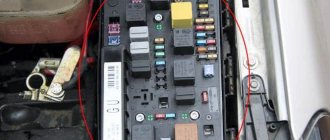
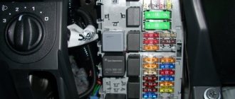
The main mounting block is located at the end of the dashboard on the driver's side.
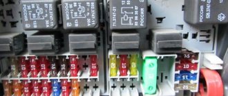
Fuse diagram
| № | Current, A | Decoding |
| 1 | 5A | Heating of windshield washer nozzles |
| 2 | 10A | Direction indicators |
| 3 | 5A | Headlight washer relay. Lighting; glove box. engine compartment, air conditioning, automatic transmission. dashboard |
| 4 | 5A | License plate light |
| 5 | 10A | Instrument panel, heated seats, automatic transmission display. mirror switch, airbag lamp, outside temperature indicator, navigation system, parking lights |
| 6 | 5A | central locking |
| 7 | 10A | ABC system |
| 8 | 5A | Telephone |
| 9 | 10A | Heater for mirrors and door locks |
| 10 | 5A | Headlights corrector |
| 11 | 5A | Cruise control (automatic transmission) |
| 12 | 10A | Built-in diagnostics |
| 13 | 10A | Brake lights |
| 14 | 10A | Interior lighting, reading lights, anti-theft system, passenger visor mirror |
| 15 | 10A | Instrument panel, automatic transmission [4-speed], air conditioning, navigation system |
| 16 | 5A | ABC system |
| 17 | 10A | Heated door locks |
| 18 | 10A | 10A right high beam |
| 19 | 10A | left high beam |
| 20 | 15A | Right low beam, electric headlight adjustment |
| 21 | 15A | Left low beam, electric headlight adjustment |
| 22 | 5A | Right side lights |
| 23 | 5 | Left side lights |
| 24 | 25A | Windshield wipers, washer pump, wiper breaker relay |
| 25 | 30A | Heating fan, air conditioner |
| 26 | 30A | Heated rear window, heated mirrors, air recirculation |
| 27 | — | — |
| 28 | 15A | Engine control |
| 30 | 20A | Electric sunroof |
| 31 | 15A | Reversing lights, cruise control, automatic transmission, diagnostic connector |
| 32 | 20A | Engine control |
| 33 | 15A | Cigarette lighter |
| 34 | 15A | Engine control |
| 35 | 30 | Trailer power socket |
| 36 | 15A | Telephone, radio |
| 38 | 15A | Trunk light, central locking |
| 39 | 15A | Emergency lighting |
| 40 | Klaxon | |
| 41 | 25A | ABS system [hydraulic modulator/pump) |
| 42 | 40A | Fan |
| 43 | 5A | S-pin [central locking, radio, navigation system |
| 44 | 30 | Heated seats |
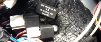
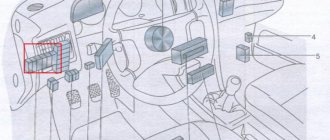
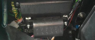
The relay modules are located on the central distribution block under the instrument panel.
Relay board description
| № | Description |
| Board A | |
| 3 | air conditioning system |
| 4 | alarm control |
| 5 | |
| 7 | — |
| 8 | daytime running lights |
| 9 | headlights |
| 10 | fog lights |
| 11 | mirror control with tilt function |
| 12 | |
| 13 | — |
| 14 | special signaling system [taxi] |
| 15 | — |
| 16 | special signaling system [taxi] |
| 17 | taximeter [taxi] |
| 18 | ABS hydraulic pump |
| transmitter [taxi] | |
| Board B | |
| 1 | Unloading relay for contact X |
| 2 | beep |
| 3 | headlight lens cleaning system |
| 4 | Automatic transmission relay (starter interlock and reverse lights) or jumper for manual transmission |
| 5 | Relay for intermittent operation of the cleaning and flushing system |
| 6 | fuel pump or glow plugs |
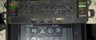
Relay location in the Audi A4 interior
On vehicles with extensive equipment, an additional board with a relay is located behind the main board.
Central switchgear - B. Relays are marked in black.
Relay description
| 1 | Unloading relay for contact X |
| 2 | Horn relay |
| 3 | Headlight cleaning system relay |
| 4 | Automatic transmission relay (starter interlock and reverse lights) or jumper for manual transmission |
| 5 | Relay for intermittent operation of the cleaning and flushing system |
| 6 | Fuel pump or glow plug relay |
Main relay board -A-
| 3 | Magnetic clutch relay (air conditioning system) |
| 4 | Alarm control unit |
| 5 | Alarm control unit |
| 7 | — |
| 8 | Daytime running light relay |
| 9 | Headlight relay |
| 10 | Fog light relay |
| 11 | Control unit for mirror with tilt function |
| 12 | Control unit for mirror with tilt function |
| 13 | — |
| 14 | Fuse for special signaling system [taxi] |
| 15 | — |
| 16 | Fuse for special signaling system [taxi] |
| 17 | Fuse for taximeter [taxi] |
| 18 | Hydraulic pump fuse [ABS] Transmitter fuse [taxi] |
Additional relay board Audi A4
Description
| 1 | Rear fog lights |
| 2 | Relay for fan operation at maximum speed [Lufter voll auf] |
| 3 | Fan operating mode relay at the first stage |
| 4 | Power window control unit relay |
| 5-15 | — |
| 16 | Seat adjustment fuse |
| 17 | — |
| 18 | Hydraulic pump system (ABS) fuse |
| 19 | Radiator Fan Fuse |
| 20 | — |
| 21 | Radiator Fan Switch Coil Relay |
| 22 | Rear power window relay |
| 23 | Front power window relay |
| 24 | Central locking and anti-theft relay |
Audi A4 Lucky › Logbook › Audi A4 (B5) fuse table
Connected consumers Amps 1 Heated windshield washer nozzles 5 2 Direction indicators 5 3 Glove box light, instrument panel light, headlight cleaning system 5 4 License plate light 5 5 Indicator lights in the combined instrument panel (instrument panel, reading lights ), heated seats, automatic transmission display, mirror switch, outside temperature indicator, navigation system 5 6 Central locking 5 7 Anti-lock system (ABS) 15 or 10 8 Telephone 5 9 Heated mirrors and door locks 10 10 Automatic headlight leveling 5 11 Adjustment system speed GRA (tempostat) / cruise control (automatic transmission) 5 12 Diagnostics of power supply 10 13 Brake lights 10 14 Interior lights, reading lamps, anti-theft system, illumination of the passenger mirror in the visor 10 15 Combined instrument, control units ( dashboard), air conditioning, navigation 10 16 ABS control unit 5 17 Heated door lock cylinders 10 18 High beam on the right 10 19 High beam on the left 10 20 Low beam on the right, electric headlight angle adjustment on the right 10 21 Low beam on the left , electric headlight angle adjustment on the left 10 22 Tail light on the right 5 23 Tail light on the left 5 24 Window washing/wiping system (windshield wiper, pump) 25 25 Air blower (heater blower), air conditioning system 30 26 Heated rear window, heated mirrors, air recirculation 30 27 Rear wiper 15 28 Fuel pump 15 29 Engine control (ignition/injection) 20 30 Sliding sunroof 20 31 Reversing lights, automatic transmission cruise control, control units (diagnostic connector) 15 32 Engine control (ignition/injection) 15/20 33 Cigarette lighter 15 34 Engine control (ignition/injection) 15 35 Socket (socket) for trailer connection 30 36 Fog lights, rear fog lights 15 37 Radio, telephone 20 38 Lamp for trunk lighting. Central locking device 15 39 Hazard warning system 15 40 Horn 25 41 ABS hydraulic module (ESP) 25 42 Auxiliary air fan 30 43 S-contact (central locking, radio, navigation system) 5 44 Heated seats 30
On an 8-seater additional support In an additional socket Connected consumers Amps 18 Hydraulic pump ABS 50 19 Electric radiator fan 40 21 Radiator fan relay coil 5 22 Electric rear window 30* 23 Electric front window 30* 24 Central locking and anti-theft alarm system 15 *
Optional relay board
| 1 | Rear fog lights |
| 2 | Relay for fan operation at maximum speed |
| 3 | Fan operating mode relay at the first stage |
| 4 | Power window control unit relay |
| 5-15 | — |
| 16 | Seat adjustment fuse |
| 17 | — |
| 18 | Hydraulic pump system (ABS) fuse |
| 19 | Radiator Fan Fuse |
| 20 | — |
| 21 | Radiator Fan Switch Coil Relay |
| 22 | Rear power window relay |
| 23 | Front power window relay |
| 24 | Central locking and anti-theft relay |
Electronics unit relay board in the engine compartment
Located in the mounting block
General scheme
Table with description in Russian
| 1 | Oxygen sensor heater relay Glow plug relay I - coolant |
| 2 | Glow plug relay II - coolant |
| 3 | Diesel direct injection relay |
| 4-5 | — |
| 6 | Engine electrical fuse |
| 7 | Glow plug fuse I - coolant |
| 8 | Glow plug fuse II - coolant |
| 9 | Glow plug fuse |
Audi A4 relay location
A relay is a small coil of wire around a central iron core. When an actuated switch energizes the coil, this core moves heavy-duty contacts together, thereby allowing large current to flow to the device. The operation of the relay affects the operation of the horns, air conditioning compressor, power windows, engine cooling fans and overhead power panels, low and high beam headlights. This is important to know because many electrical faults occur in the relays themselves.
The Audi A4 relay location diagram is shown in the figure
Explanation of board "A"
- Auxiliary Ignition Relay
- 2-tone horn relay
- Headlight washer pump relay
- Automatic transmission relay, manual transmission axle
- Washer/Wiper Intermittent Relay
- Fuel pump relay, glow plug relay
Explanation of board "B"
- Rear window washer pump relay
- A/C compressor clutch relay
- Lamp warning module relay
- Lamp warning module relay
- Headlight relay
- High beam relay
- Front fog lamp relay
- Folding Mirror Control Module Relay
- Folding Mirror Control Module Relay
- Starter Disable Switch Relay/Backup Lamp Relay, with AT/4-Speed
- Taxi alarm relay
- Taximeter relay
- Taxi Two Way Radio Relay
Electronics unit relay board in the engine compartment
The relay board of the engine compartment electronics unit in the Audi A4 B5 is located in a special mounting block.
- Oxygen Sensor System Relay (2.6 ABC), Engine Coolant Heater Relay I
- Engine Coolant Heater Relay II
- Diesel injection relay
- Empty nest
- Empty nest
- Injection system
- Engine coolant heating element I
- Engine coolant heating element II
- Glow plug system
Optional relay board
- Rear fog lamp relay
- Engine Coolant Fan Timer Relay (Max Speed)
- Engine Coolant Fan Timer Relay (Min Speed)
- Power Window Circuit Relay
5-15 Empty Socket
16 Seat adjustment relay
17 Empty Nest
18 Anti-lock braking system pump fuse
19 Coolant fan motor fuse
20 Empty Nest
21 Engine coolant fan switch relay
22 Relay for electric rear windows
23 Relay for electric front windows
24 Central locking relay
How to remove and repair the cigarette lighter
To find the cigarette lighter fuse, you need to carefully read the block diagram. Then you can begin the repair itself:
- Open the trunk and find the desired block under the trim on the right.
- Take out the fixing bar. You can pull the part out by hand.
- Remove the fuse from socket F40 and 15 A.
- Remove the old one and connect the new one. If everything is done correctly, the cigarette lighter will work.
Some drivers mistakenly think that all cigarette lighters are the same. In fact, they are similar in appearance. If your car does not have a rear cigarette lighter, you can install a front one. Then you will need to drill a suitable hole in the panel.
From time to time, any cigarette lighter needs revision. A simple procedure will allow you to install it correctly and avoid problems with operation. To do everything properly, you need to:
- Remove the backlight lamp. It stands on a special slide and is secured with a latch. For convenience, it is highlighted in black.
- To remove the light bulb, pry the lock with a small screwdriver, lifting it up. Then pull it out along the slide.
- The lamp leads are welded to the socket contacts. If you need to replace it, press the pad marked in black. Then loosen the light bulb, tear it away from the contacts and take it out. You can not only install a similar new one, but also an LED one.
- Disconnect the pad from the lamp to solder it to a simple or LED one.
- Change the light bulb and reassemble. An LED strip would be a good alternative. It has brighter illumination.
- Remove the clip that holds the lamp in the socket. It is attached with latches. Pull one of them aside.
- When installing the LED strip, previously removed elements will not be required. Wrap the filter around it and solder the contacts. One contact should be on the light body, and the other should be on the top of the contact pad.
Additionally, you can install LEDs in the keys, and the tape looks good on stove knobs. All that remains is to disassemble the cigarette lighter completely. Separate it from the outer panel. It is fixed with filter latches. Press the locks and push the cigarette lighter out. Then disconnect the light filter from the latches by pressing them to the sides. Pull it off, clean it well and reassemble in reverse order.
- Alarm Starline A6
- Why doesn't the cigarette lighter work?
- Why the cigarette lighter does not work on the VAZ 2107
- Where is the Nissan Tiida cigarette lighter fuse located?
Audi A4 relay location.
On vehicles with extensive equipment, an additional relay board is located behind the main board. Central switchgear - B. Relays are marked in black.
Decoding
| 1 | Unloading relay for contact X |
| 2 | Horn relay |
| 3 | Headlight cleaning system relay |
| 4 | Automatic transmission relay (starter interlock and reverse lights) or jumper for manual transmission |
| 5 | Relay for intermittent operation of the cleaning and flushing system |
| 6 | Fuel pump or glow plug relay |
Main Relay Board - A
| 3 | Magnetic clutch relay (air conditioning system) |
| 4 | Alarm control unit |
| 5 | Alarm control unit |
| 7 | — |
| 8 | Daytime running light relay |
| 9 | Headlight relay |
| 10 | Fog light relay |
| 11 | Control unit for mirror with tilt function |
| 12 | Control unit for mirror with tilt function |
| 13 | — |
| 14 | Fuse for special alarm system |
| 15 | — |
| 16 | Fuse for special alarm system |
| 17 | Fuse for taximeter |
| 18 | System Hydraulic Pump Fuse Transmitter Fuse |
Nomenclature numbers of fuses and relays Audi A4 (B5)
| Item name | Item number | ||
| Knife. fuse 10/2×2.8 5A(light brown) | VAG N10 261 501 | ||
| Knife. fuse 10/2×2.8 10A(red) | VAG N10 261 503 | ||
| Knife. fuse 10/2×2.8 15A (blue) | VAG N10 261 507 | ||
| Knife. fuse 19/2×5 15A(blue) | VAG N01 713 112 | ||
| Knife. fuse 19/2×5 20A(yellow) | VAG N01 713 113 | ||
| Knife. fuse 19/2×5 25A (transparent) | VAG N01 713 114 | ||
| Knife. fuse 19/2×5 30A(light green) | VAG N01 713 115 | ||
| Delay relay for vehicles with manual air conditioning control | VAG 8D0 919 578 A | ||
| X-contact relief relay | VAG 8D0 951 253 | ||
| Horn relay | VAG 141 951 253B | ||
| Headlight washer relay | VAG 8L0 955 535 | ||
| Windshield washer/wiper control unit | VAG 191 955 531 | ||
| Fuel pump make contact relay | VAG 4D0 951 253 | ||
| Taxi alarm relay | VAG 443 953 233 | ||
| Glow plug control unit | VAG 8A0 951 253 | ||
| Control unit for headlight/brake light control system | VAG 8D0 919 471 | ||
| Rear wiper control relay | VAG 141 951 253 B | ||
Hong Kong police crack down on street racing
Additional relay block Audi A4 (B6)
| № | Purpose of relays and fuses |
| 1 | Free connector |
| 2 | Relay for low heating output |
| 3 | Relay for high heating output |
| A | Fuse for independent heater |
| B | Glow plug fuse 1 |
| C | Glow plug fuse 2 |
Audi A4 fuses
The Audi A4 is a highly sought-after sedan car model in almost all regions of the Russian Federation - high build quality, elitism of the model and thoughtful equipment provide the owner with safety and comfort in the cabin, regardless of operating conditions. However, for stable operation of the vehicle, all vehicle systems must be serviced in a timely manner, in particular, monitor the electrical components of the vehicle and replace damaged fuses.
Location of electronic control units
1 Air conditioning control unit - in the heater control panel - functions: Rear window defroster, front seat heaters, steering wheel heater 2 Air conditioning/heater fan control unit - fan unit 3 Antenna selection control unit (sedan with 'Concert II/Symphony II' audio system) - rear roof panel, centered 4 Antenna signal amplifier (saloon with 'ChorusII' audio system) - rear roof panel, centered
7 Crash sensor, driver's side - engine compartment 8 Crash sensor, passenger's side - engine compartment 9 Vehicle tilt sensor (anti-theft system) - in multifunction control unit 2 10 Anti-theft system horn - luggage compartment, behind the right trim panel 11 Change sensor volume (anti-theft system) - front interior lamp 12 Audio output amplifier - luggage compartment, behind the right trim panel 13 Additional heater control unit - behind the left front wheel arch 14 Battery 15 Clock synchronization unit (with digital multifunction display) - behind the rear bumper 16 Diagnostic connector (DLC) - under the dashboard, driver's side 17 Diagnostic unit - on the dashboard 18 Door function control unit, front left (central locking / door mirror / window regulator) - door 19 Door function control unit, front right (central locking/door mirror/window lifter) - door 20 Door function control unit, rear left (central locking/window lifter) - door 21 Door function control unit, rear right (central locking/window lifter) - door 22 Unit cooling fan motor control - on the radiator 23 Fuse/relay block, instrument panel 1 24 Fuse/relay block, instrument panel 2 25 Fuse/relay block, instrument panel 3 26 Fuse/relay block, instrument panel 4 27 Fuse/relay block5, Dashboard-Taxi 28 Fuse/Relay Box, Dashboard 6-Taxi 29 Fuse/Relay Box, Engine Compartment - Under ECM/TCM 30 Auxiliary Fuse (150A) - Battery Positive 31 Headlight Control Box, Left (Xenon Headlight Models) 32 Headlight control unit, right (models with xenon headlights) 33 Headlight level control unit (models with xenon headlights) - behind the glove box 34 Windshield defogger timer relay - next to battery 35 A/C/heating fan control unit/speed control resistor fan 36 Horn - behind front bumper 37 Immobilizer control unit - in instrument cluster 38 Immobilizer ring antenna - near ignition switch 39 Instrument cluster control unit/digital multifunction display - on instrument cluster - functions: Immobilizer, warning devices and indicators 40 Multifunction control unit 1 - front left footwell - functions: Anti-theft system, central locking, power/heated door mirrors, power windows, interior lamps, sunroof 41 Multifunction control unit 2 - under the fuse/relay box 2 - instrument panel - functions: Headlights /lights, headlight washers, horn, turn signals/hazard warning lights, rear window wiper, windshield washer, windshield wiper 42 Electronic transmission control unit - on the transmission (Multitronic) 43 Navigation system antenna, sedan - rear roof panel 45 Reader navigation system - in the glove compartment 46 Navigation system control unit - luggage compartment, behind the left trim panel 47 Navigation system interface control unit - luggage compartment, behind the left trim panel 48 Outside temperature sensor - behind the front bumper 49 Parking system control unit - behind the left rear light 50 Parking system buzzer, front - under the dashboard (driver's side) 51 Parking system buzzer, rear - sedan - under the rear parcel shelf 53 Seat heater control unit, front - in the air conditioning control unit 54 Seat heater control unit, rear left - in the switch - center console, rear 55 Seat heater control unit, rear right - in the switch - center console, rear 56 Side impact sensor, front left - lower part of the B-pillar 57 Side impact sensor, front right - lower part of the B-pillar 58 Side impact sensor, rear left - lower part of the C-pillar 59 Side impact sensor, rear right - lower part of the C-pillar 60 SRS control unit - under the center console, in the center 61 Steering column electrical control unit - functions: Cruise control, position sensor steering wheel 62 Body height sensor, front (models with xenon headlights) - above the lower suspension arm 63 Body height sensor, rear (models with xenon headlights) - above the lower suspension arm 64 Telematics units / telephone control unit - front right space for 65 Telephone interface control unit (cell phone) - front right footwell 66 Telephone transceiver/telephone amplifier - luggage compartment, behind the right trim panel 67 Trailer electrical control unit - luggage compartment, behind the left trim panel 68 Electronic transmission control unit 69 Unit control system for tire pressure monitoring - luggage compartment, behind the left trim panel 70 Vehicle speed sensor - →2002 - gearbox 71 Voice synthesizer control unit (telematics) - front right footwell
Audi A4 relay location
A relay is a small coil of wire around a central iron core. When an actuated switch energizes the coil, this core moves heavy-duty contacts together, thereby allowing large current to flow to the device. The operation of the relay affects the operation of the horns, air conditioning compressor, power windows, engine cooling fans and overhead power panels, low and high beam headlights. This is important to know because many electrical faults occur in the relays themselves.
The Audi A4 relay location diagram is shown in the figure
Explanation of board "A"
- Auxiliary Ignition Relay
- 2-tone horn relay
- Headlight washer pump relay
- Automatic transmission relay, manual transmission axle
- Washer/Wiper Intermittent Relay
- Fuel pump relay, glow plug relay
Explanation of board "B"
- Rear window washer pump relay
- A/C compressor clutch relay
- Lamp warning module relay
- Lamp warning module relay
- Headlight relay
- High beam relay
- Front fog lamp relay
- Folding Mirror Control Module Relay
- Folding Mirror Control Module Relay
- Starter Disable Switch Relay/Backup Lamp Relay, with AT/4-Speed
- Taxi alarm relay
- Taximeter relay
- Taxi Two Way Radio Relay
Electronics unit relay board in the engine compartment
The relay board of the engine compartment electronics unit in the Audi A4 B5 is located in a special mounting block.
- Oxygen Sensor System Relay (2.6 ABC), Engine Coolant Heater Relay I
- Engine Coolant Heater Relay II
- Diesel injection relay
- Empty nest
- Empty nest
- Injection system
- Engine coolant heating element I
- Engine coolant heating element II
- Glow plug system
Optional relay board
- Rear fog lamp relay
- Engine Coolant Fan Timer Relay (Max Speed)
- Engine Coolant Fan Timer Relay (Min Speed)
- Power Window Circuit Relay
5-15 Empty Socket
16 Seat adjustment relay
17 Empty Nest
18 Anti-lock braking system pump fuse
19 Coolant fan motor fuse
20 Empty Nest
21 Engine coolant fan switch relay
22 Relay for electric rear windows
23 Relay for electric front windows
24 Central locking relay
Audi A4 Club
Each electrical device in a car only needs a certain, precisely set amount of current. In accordance with this current consumption in a given electrical circuit, the cross-section of its wire was naturally determined. If the current consumption in this electrical circuit increases, for example, due to an additional consumer connected or as a result of a short circuit, then the wire is overloaded. In this case, the wire heats up or even glows if the current supply is not interrupted in time. This is what fuses do.
To ensure that your Audi A4 does not become completely de-energized when a defect occurs, fuses are integrated into various electrical circuits. Although the electrical circuits between the battery, generator, starter and ignition switch are not controlled by fuses. Replacing fuses If one of the plug fuses needs to be replaced, then for this purpose you can use the small plastic pliers that are attached to the cover of the fuse box (on the left end side of the dashboard). Please note that the Audi A4 has smaller fuses (miniature fuses) than previous models. If the new fuse blows immediately, find out if the fuse was installed too weak. If this is not the case, then use the fuse table to identify the connected consumers and check them one by one. The corresponding electrical circuit will help you with this. If in doubt, disconnect all consumers and reconnect one by one. The consumer, whose connection would blow the fuse, was faulty. Additional fuses With certain advanced configurations, auxiliary fuses are located on the 8-station auxiliary relay support on the left under the instrument panel. In this case, most often we are talking about so-called thermal fuses. These are fuses that, when an electrical circuit is overloaded, interrupt the flow of current for a certain time and then restore the connection again.
Inside, in the trim (3) of the left end side of the instrument panel, there are small plastic pliers (2) in a clamp for removing fuses, and a crank (4) for emergency operation of the sliding roof. The figure shows the placement of fuses in the box (1).
Fuse table In fuse box
| № | Connected consumers | Amps |
| 1 | Heated windshield washer nozzles | 5 |
| 2 | Direction indicators | 5 |
| 3 | Glove box light, instrument panel light, headlight cleaning system | 5 |
| 4 | License plate light | 5 |
| 5 | Warning lights in the combined instrument panel | 5 |
| 6 | central locking | 5 |
| 7 | Anti-lock system | 15 |
| 8 | Telephone | 0 |
| 9 | No | – |
| 10 | No | – |
| 11 | Speed control system | 5 |
| 12 | Power supply diagnostics | 10 |
| 13 | Brake lights | 10 |
| 14 | Interior lights | 10 |
| 15 | Combined instrument, control units | 10 |
| 16 | ABS control unit | 5 |
| 17 | Door lock drum heating | 10 |
| 18 | High beam right | 10 |
| 19 | Left high beam headlight | 10 |
| 20 | Low beam headlight on the right, motor for setting the headlight angle on the right | 10 |
| 21 | Low beam headlight on the left, motor for setting the headlight angle on the left | 10 |
| 22 | Taillight and parking light on the right | 5 |
| 23 | Taillight and parking light left | 5 |
| 24 | Window washing/cleaning system | 25 |
| 25 | Air blower, air conditioning system | 30 |
| 26 | Heated rear window, heated mirrors | 30 |
| 27 | No | – |
| 28 | Fuel pump | 15 |
| 29 | Ignition/injection control | 20 |
| 30 | No | – |
| 31 | Reversing lights, control units | 15 |
| 32 | Ignition/injection control | 15 |
| 33 | Cigarette lighter | 15 |
| 34 | Ignition/injection control | 15 |
| 35 | Trailer coupling socket | 30 |
| 36 | Fog lights, rear fog lights | 15 |
| 37 | Radio, telephone | 20 |
| 38 | Trunk light | 15 |
| 39 | Alarm system | 15 |
| 40 | Horn | 25 |
| 41 | ABS hydraulic module | 25 |
| 42 | No | – |
| 43 | No | – |
| 44 | Heated seats | 30 |
On 8-seater additional support
| In an additional slot | Connected consumers | Amps |
| 18 | ABS hydraulic pump | 50 |
| 19 | Electric radiator fan | 40 |
| 21 | Radiator Fan Relay Coil | 5 |
| 22 | Rear electric window | 30* |
| 23 | Electric front window lift | 30* |
| 24 | Central locking and anti-theft alarm system | 15* |
*Circuit breaker
DIY Audi A4 fuses replacement
All on the topic Replacing Audi A4 fuses
- Bastien
- Often the rxx jumps out and the connection to + is broken; the third rxx switch has already been changed. xx 760-870 chain checked, no break
- Hermes Tamanaev
- in short, near the gas pedal there are all the heater levers, we climb in and study how to set them up, because the cables cannot be reached right away and they may fall off and you will have to remove the panel, for which there is no time
- Gadji Drain
- Thanks, did it help?
- Aybar
Bro, I’ll give you two reasons for the future... Even three... First: the compressor magnet may burn out... Everything on your panel lights up, but nope... It doesn’t work... The second reason is that many cars have a pressure sensor on the Conder... If it fails- all your dances with tambourines are useless... But checking it is another story... And the third reason why the air conditioner may not turn on: - on many cars the compressor-additional fan system is looped... And if something is wrong with the ventilator, it won’t start for you compressor... So sorry, your video is nothing... There are five times more reasons,
Morina Shurygina
These are not Volgovsky ones! I had this on my two-wheeler back in 2010! 'Volgovskie' ones are twice as big, firstly, and secondly, I bought myself 'Volgovskie' ones in 2022, they cost 1500 rubles per pair, they are sold as a pair, in a box, in 'gas' stores!!! They're blowing so hard!!!
- Andi Babunashvili
- Can I invite you to Izhevsk for the same work on the engine?
- Lucero
Fabulous fucking...
- Richat
- Good afternoon, where did you get the rivets?
- Ranita
Good afternoon How can I reach you?
Jaye
Damn, I’m crap on your pelvis, it’s not like hemorrhoids are with her every day. Every day something breaks. For 10 years I’ve only changed the oil and consumables, but it’s the problem, not the car.
Vicky
but I have one trick: I press the signal, the signal clicks, but it doesn’t turn off the envy of the car, then it beeps, but the signal is not set up, and while driving, it’s not like food.. the signal works for a direct signal.
Sule
Thank you! Very relevant!
- Pablo
- Vangs me that the battery is about four years old on short trips
- Geraghty
- At what degrees does your radiator fan turn on?
- Maiko
Alexey won't get it. Better find out where the relay is located if possible. will wait. Good luck
William
1.9 should be taken. I sold it, glad I sold it)))
Len
Your engines will be fucked up guys if you do 180!!!
Nurlan
I have 605 2.1td. If you were surprised at this block, then throw the rug on the threshold so as not to break the ridge. I have 2 meals (can you help) not to disturb the tachometer (I can’t find the chip in the engine.
help) and the other heater fan died. The best fuse (10 amps under the dashboard on the passenger side) remembering, after 5-10 km the fan died and the heater began to blow cold (thus falling 300 km to Kiev.
) Well, let’s look for the reason?
Milka
Hey brother! Great video! Any chance you can tell me if this would work for other 4cyl Nissan engines of the same year (I have Nissan Xtrail a Canadian model with a similar looking engine bay. Ill do more research myself but if you KNOW that'd be great! Thanks !
Write a comment
Source: https://chinusam.ru/audi-a4/predohraniteli/
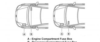
Main fuse box location
p, blockquote 3,0,0,0,0
It is located inside the car on the left side of the panel. Inside, in the trim (3) of the left end side of the instrument panel, there are small plastic pliers (2) in a clamp for removing fuses, and a crank (4) for emergency operation of the sliding roof. The figure below shows the placement of fuses in the box (1).
p, blockquote 4,0,0,0,0
The relays are located on the central switchgear board under the instrument panel behind the left footwell cover.
p, blockquote 5,0,1,0,0 photo of a block with fuses and a relay block
p, blockquote 6,0,0,0,0
Fuse description table
Fuse number 33 at 15A is responsible for the cigarette lighter.
We considered Audi A4 and Audi A4 Avant cars produced in 1994, 1995, 1996, 1997, 1998, 1999, 2000, 2001. At first, only the sedan version was available, the station wagon (Avant) appeared a year later. The car is based on the same platform as the fifth generation Volkswagen Passat.
The location of the Audi A4 fuses may differ depending on the year of manufacture. The relays are located on the central switchgear board under the instrument panel behind the left footwell cover.
How to fix this problem
To detect a malfunction, you will need a multimeter or automotive tester. First of all, you need to check the serviceability of fuse number 33, which should withstand a load with a current consumption of approximately 15 amperes. A faulty device is replaced with a known good one, and if it is in working condition, the search continues. Just in case, you need to check the presence of on-board voltage at the fuse legs.
Next you need to figure out the voltage supply to the cigarette lighter terminals. This is not difficult to do; just attach one multimeter probe to the central electrode, and the second to the side terminal of the cigarette lighter socket. If the device indicates the presence of voltage, you should check its heating element. If no voltage is detected in the socket, you will have to disassemble it.
To inspect the connection of the wires to the cigarette lighter, use a thin screwdriver to pry up the console in the area of the handbrake lever and, pulling it up, remove it. After this, it will be possible to inspect and check the wire connections. If there are no wire breaks, you should check them for breaks.
Share this article with your friends:
Which fuses need to be replaced?
A fuse is a low resistance device that protects a circuit from overload. If a short piece of wire melts or breaks when exposed to excess electrical current, the fuse should be replaced. The unit should be periodically checked for faulty fuses or those that will soon become unusable. What fuses should I choose to replace?
Visual inspection of fuses - inspection of each fuse for faults. The fuse box has a diagram showing the name and location of each fuse. With the vehicle completely turned off, locate the appropriate fuse and remove it by grasping it firmly using a fuse puller stored in the fuse box or a pair of pliers. To visually inspect the fuse, you need to hold the fuse up to a light and check the metal wire for damage or breakage.
If damage is detected, the fuse will have to be replaced.
How to replace faulty fuses on an Audi A4 with your own hands
The procedure for finding and replacing failed fuses can be done with your own hands - to service any of the car units you only need 15 minutes of free time, as well as access to a specialized puller or pliers and a slotted screwdriver.
The procedure for replacing fuses on an Audi A4 is carried out according to the following scenario:
- First of all, you need to disconnect the battery from the car's network to prevent voltage surges when replacing fuses or fuse links. This will protect the vehicle equipment from a sharp decrease in service life;
- Next, under the hood, on the right side of the power unit, we find a block, inside of which there are fuses for the engine compartment. The cover is removed using the tip of a slotted screwdriver;
- Then we carry out a visual inspection of all fuses and, using pliers or a specialized puller, remove the faulty ones. Faulty fuses will have traces of melting on the body and a completely deformed spiral inside the plastic;
- We install new fuses by lightly pressing on the seating cell in the block until a characteristic click is formed;
- After successfully servicing the engine block, we take you to the vehicle’s interior, where we repeat a similar procedure in the cabin. Inside the car, the fuse box responsible for the functions included in the package will be located on the left side of the steering wheel, at the bottom of the dashboard.
After replacement, we connect the battery to the car and be sure to test all the functions in the car before the first trip on the road.
Fuse box in the Audi A5 interior
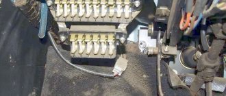
The mounting block in the cabin is located, like most VAG cars, on the left side of the control panel.
- fuse box
- fuse removal tweezers
- lid
- crank for emergency hatch control.
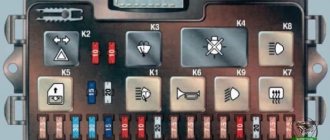
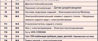
Fuse box diagram in the Audi A4 interior
| Purpose of Audi A4 fuses | |
| 1 | 5A - Heating of windshield washer nozzles |
| 2 | 10A - Direction indicators |
| 3 | 5A - Headlight washer relay. Lighting: glove box, engine compartment, air conditioning, automatic transmission instrument panel |
| 4 | 5A - License plate lighting |
| 5 | 10A — Instrument panel, heated seats, automatic transmission display. mirror switch, Airbag pump, outside temperature indicator, navigation system, parking lights |
| 6 | 5A - Central locking |
| 7 | 10A - ABS system |
| 8 | 5A - Telephone |
| 9 | 10A - Heated mirrors and door locks |
| 10 | 5A - Headlight range control |
| 11 | 5A — Cruise control [automatic transmission] |
| 12 | 10A - Built-in diagnostics |
| 13 | 10A - Brake lights |
| 14 | 10A - Interior lighting, reading lamps, anti-theft system, passenger mirror in the visor |
| 15 | 10A - Instrument panel, automatic transmission [4-speed], air conditioning, navigation system |
| 16 | 5A - ABS system |
| 17 | 10A - Heated door locks |
| 18 | 10A - right high beam |
| 19 | 10A - Left high beam |
| 20 | 15A - Right low beam, electric headlight adjustment |
| 21 | 15A - Left low beam, electric headlight adjustment |
| 22 | 5A - Right side lights |
| 23 | 5A - Left side lights |
| 24 | 25A - Windshield wipers, washer pump. Wiper Interrupter Relay |
| 25 | 30A - heater fan, air conditioner |
| 26 |
Relay location in the Audi A4 interior
On vehicles with extensive equipment, an additional board with a relay is located behind the main board.
Central switchgear - B. Relays are marked in black.
| 1 | Unloading relay for contact X |
| 2 | Horn relay |
| 3 | Headlight cleaning system relay |
| 4 | Automatic transmission relay (starter interlock and reverse lights) or jumper for manual transmission |
| 5 | Relay for intermittent operation of the cleaning and flushing system |
| 6 | Fuel pump or glow plug relay |
Main relay board -A-
| 3 | Magnetic clutch relay (air conditioning system) |
| 4 | Alarm control unit |
| 5 | Alarm control unit |
| 7 | — |
| 8 | Daytime running light relay |
| 9 | Headlight relay |
| 10 | Fog light relay |
| 11 | Control unit for mirror with tilt function |
| 12 | Control unit for mirror with tilt function |
| 13 | — |
| 14 | Fuse for special signaling system [taxi] |
| 15 | — |
| 16 | Fuse for special signaling system [taxi] |
| 17 | Fuse for taximeter [taxi] |
| 18 | Hydraulic pump fuse [ABS] |
Additional relay board Audi A4
Description
| 1 | Rear fog lights |
| 2 | Relay for fan operation at maximum speed [Lufter voll auf] |
| 3 | Fan operating mode relay at the first stage |
| 4 | Power window control unit relay |
| 5-15 | — |
| 16 | Seat adjustment fuse |
| 17 | — |
| 18 | Hydraulic pump system (ABS) fuse |
| 19 | Radiator Fan Fuse |
| 20 | — |
| 21 | Radiator Fan Switch Coil Relay |
| 22 | Rear power window relay |
| 23 | Front power window relay |
| 24 | Central locking and anti-theft relay |
Sources
- https://carpod.ru/predohraniteli-audi-a4-1995-2000-g-v_607.htm
- https://avtoblokrele.com/blok-rele-i-predohranitelej-audi-a4-b5/
- https://FokSevmash.ru/hodovaya-chast-i-transmissiya/predohraniteli-audi-a4-b5.html
- https://avtoehlektrika.ru/oborudovanie/gde-predohraniteli-audi-a4-b5.html
- https://vsepredohraniteli.ru/audi/a4-b5-predohraniteli-i-rele.html
- https://servcar.ru/rukovodstva/europa/audi/audi-a4-8ex-01-08-predokhraniteli-i-rele
- https://carsclick.ru/audi/osnashhenie-i-obsluzhivanie/kak-rasshifrovat-kartu-predohranitelej-v-audi-a4-b5/
[collapse]