The brake force regulator, popularly known as the “sorcerer”, is one of the components of the car’s braking system. Its main purpose is to prevent the rear axle of the car from skidding when braking. In modern cars, the mechanical regulator has been replaced by an electronic EBD system. In this article we will find out what a “sorcerer” is, what elements it consists of and how it works. Let's look at how and why this device is adjusted, and also find out the consequences of operating a car without it.
Pneumatic brake force regulator
The pneumatic regulator of the braking forces of a KamAZ vehicle, installed on the spar 7 of the vehicle frame, consists of an automatic regulator 2 of the lever 3, an adjustable rod 4, an elastic element 5, a compensator 7, connected by a rod 6 to the beams 8 and 9 of the vehicle axles. The mechanisms and available fastenings provide compensation for trolley distortions that are possible when braking on uneven roads. The elastic element protects the regulator from damage during vertical movements of the rear bogie axles, and also softens sharp shocks and reduces vibration.
Rice. Installation diagram of the brake force regulator: 1 - spar; 2 — brake force regulator; 3 — regulator lever; 4 - traction; 5 - elastic element; 6 — rod; 7 - compensator; 8, 9 — bridge beams; I — position of the regulator lever at the highest axial load (“loaded” vehicle); II - lever position at the lowest load (“empty” car)
Let's consider the design and principle of operation of the pneumatic brake force regulator.
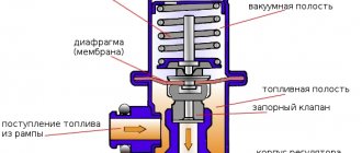
Rice. Automatic brake force regulator: a - general view; b - design; 1 - valve; 2 - stepped piston; 3 - pusher; 4 — lever; 5 — membrane (diaphragm); 6 — ball heel; 7 - piston; 8 — pusher guide; 9 — inserts in the body; 10 — connecting tube; 11 — piston ribs; I, II - cavities; III - release into the atmosphere
For a loaded vehicle, lever 4 is in its uppermost position. When braking, compressed air enters cavity 1. Therefore, piston 2 will move down, and through tube 10, air from cavity I will enter the lower part and put pressure on the plunger-type piston 7, pressing the ball heel 6 to the pusher 3. When piston 2 moves down valve 7 moves with it, which, by means of a pusher, will first disconnect cavity II from the outlet to the atmosphere, and then move away from the piston seat 2. As a result, cavity I will connect with the outlet cavity II, and compressed air will flow through cavity II to the brake chambers of the wheels.
The insert in the body has inclined ribs I on which the membrane (diaphragm) 5 rests when the piston 2 is in the upper position. Piston 2 also has ribs 11. The lower the lever and the associated pusher go, the lower the piston 2 will go. Consequently, the working area will increase membrane 5 acting on piston 2.
When the lever is in the up position (at full axial load), the pushrod is also at the top. To open the valve, piston 2 must move down. When it moves slightly, the inclined ribs 11 of the piston 2 do not extend below the ribs 9 of the insert. In this case, the membrane rests only on the edge of the insert, and the force from it is not transmitted to piston 2.
When the lever is in its lowest position (lowest axial load), piston 2 must move downwards as much as possible to open the valve, since the pusher will also be in the lower position. In the case of maximum downward movement of piston 2, its inclined ribs will drop below the ribs of the insert. In this case, the active area of the membrane becomes largest. As a result, an air pressure will be established in cavity II approximately equal to 1/3 of the pressure at the inlet to the regulator.
When the wheels are released, the air pressure in cavity 1 will drop and piston 2 will move up. In this case, the valve will sit on the piston seat 2, separating cavities I and II, and will come off the pusher. As a result, compressed air from the brake chambers of the wheels of the middle and rear axles escapes into the atmosphere through cavity II and the hollow pusher, bending the edges of the rubber valve. And all elements of the regulator return to their original position.
The considered regulators adjust the pressure of the working fluid (air) to ensure simultaneous blocking of the wheels of the front and rear axles. In this case, proactive blocking of the front axle wheels occurs. However, this method of braking is not the most effective and safe from the point of view of maintaining vehicle stability when braking. In addition, excessive tire wear occurs.
What happens if you drive without a regulator?
If the check shows that the “sorcerer” does not work, then the car owner has two options. The first and most correct is to purchase and install a new regulator. The second option is to remove the “sorcerer” from the system. Let's look at the dangers of operating a car without this device. Some owners even intentionally remove the regulator to reduce braking distance.
However, experts do not recommend removing the mechanism - this path is wrong. Without an adjuster, both the front and rear brakes will apply at the same time. The risk of a possible accident increases - the driver moving behind may not have time to react correctly to the braking process.
The presence of a working brake force regulator on the 2114 VAZ is very important. It is prohibited to remove it from the system - this is indicated in the traffic regulations. If the mechanism is not working properly, you can try to adjust it.
ABS
The coefficient of adhesion between wheels and the road depends on the degree of their sliding, which varies from 0 (pure rolling of the wheel) to 100% (complete slipping or sliding when the wheels are locked). The maximum values of the coefficient of adhesion of the order of 10... 30% (depending on the road surface) will be when the wheels slip. Consequently, with this coefficient and degree of wheel slip, the greatest efficiency and safety of braking can be ensured. This is exactly what ABS provides.
All modern ABS are self-adjusting automatic systems. They include:
- wheel speed sensors
- electronic decision block
- pressure modulators
When ABS is operating, the signal from the wheel angular speed sensors is fed to an electronic decision unit, in which, in accordance with a given program, control signals are generated and sent to the modulator.
Rice. Diagram of the pneumatic ABS modulator (a) and its characteristics (b): 1, 5, 6 - valves; 2, 3 - electromagnets; 4 - piston; A—D—cavities; p—pressure; t — time
The figure shows a diagram of the pneumatic ABS modulator and its characteristics (change in braking force over time). ABS operation is accompanied by a multi-cycle process of automatically releasing and braking the vehicle's wheels. In each cycle there are phases of automatic release of the brakes, “holding” and braking (dashed lines in Fig. b) of the wheels. There are ABS in which a two-phase cycle is carried out (there is no “holding” phase). ABS operation ensures the required angular speed of the wheel and its sliding, corresponding to maximum traction characteristics.
There is no room for optimism in brake operation
Many cars continue to drive with a completely soured regulator, because their owners do not understand the full role of this simple device and are not even aware of its existence. It turns out that the operation of the rear brakes depends on the position of the regulator piston in which it soured and lost mobility. The car will either greatly lose in braking efficiency; in fact, only the front axle works, or, on the contrary, it constantly throws the rear during hard braking due to the beginning of a skid. This can happen with impunity only until the first emergency braking from high speed. After which the driver will not even have time to understand anything, so quickly he will find himself flying forward into the oncoming lane with the trunk.
The operation of the regulator must be checked at each maintenance according to the instructions. The piston must be mobile and the clearance must be within the normal range. And the stand indicators correspond to the passport data. The only thing that saves you from these procedures is the fact that the “sorcerer” has not been used in modern cars for a long time, and its role is assigned to an electronic system, designed and tested in completely different ways. But when buying an older car, you should remember the presence of such a device.
Operation of the pneumatic modulator
Let us consider in detail the operation of a pneumatic modulator made on the basis of an accelerator valve (Fig. a). Compressed air from the brake valve enters through the line into cavity A and then passes through cavity B into cavity C and presses down on the follower piston 4. The piston moves down and rests against valve 5, disconnecting cavity G from the outlet to the atmosphere. Further downward movement of the piston leads to the opening of valve 5.
As a result, compressed air begins to pass from the receiver through cavities D and D into the brake chambers.
If the braking wheel begins to lock, the electronic unit simultaneously sends control signals to electromagnets 2 and 3, which close valve 1 and open valve 6. In this case, cavities B and C are connected to the atmosphere - the wheel is automatically released. At some angular acceleration of the wheel, the electronic unit removes the electrical voltage from electromagnet 3. As a result, valve 6 closes again under the action of a spring and the holding phase begins.
The phase of repeated automatic braking of the wheel occurs when the wheel acquires a threshold angular acceleration. In this case, the electronic unit removes the electrical voltage from electromagnet 2, which allows valve 1 to open and connect working cavity B to the main line. Then the cycle repeats.
The principle of operation of a brake caliper and why it is needed at all
Welcome! A brake caliper is essentially a very necessary thing, since practically no car can do without it, because the brake caliper does the most basic work during braking, but not all people know how it works and what will happen if it doesn’t installed on the car, that’s what we’ll look at today.
Note! At the end, in addition to this article, there is an interesting video clip that shows the entire principle of operation of the brake system!
What is a caliper for and what is its operating principle?
In short, it is needed so that the car slows down when you press the brake pedal and if it is not there, as was said earlier, the car will not stop at all, since the main work of braking is performed by this particular caliper.
Well, if we talk in more detail and, in addition to all this, delve into the principle of its operation, then this very principle of its operation is as follows: when you press the brake pedal, pressure occurs in the brake system, namely the piston which is located in the master brake cylinder ( This cylinder is indicated by the number 3), moves from the beginning of this cylinder to the end, thereby still collecting a little brake fluid that is in the brake reservoir (indicated by the number 5), squeezing the brake fluid forward, it goes through the hoses and thereby squeezes out the pistons that are in the caliper itself, and these pistons press on the brake pads and the car stops.
Let's look at it in more detail, for this let's first look at what this main brake cylinder is, and it represents a structure inside which there is that same piston as well as a rod that presses on it, so when you have to stop the car, you press accordingly on the brake pedal, after pressing the rod will also mix forward, thereby the piston that sits on this rod will mix, and after mixing, all the brake fluid will be pushed forward, as it were, and it will go all the way to the working cylinders themselves, which we will talk about a little lower.
Note! Let us tell you right away so that you understand one thing, this brake fluid is not compressible, so if something does not press on it, it will also press on other parts of the brake system and at the same time it will not compress!
Now the fluid will press from one end, onto all working cylinders to which hoses are connected (Hoses that are connected to the working cylinders are indicated by numbers 2 and 4 in the photo above, which shows a diagram of the brakes of a VAZ 2110 car), so after the brake fluid is the working cylinder is filled, the piston which is located in this cylinder will be squeezed out and thereby put pressure on the brake pad, and the brake pad at this moment will compress the brake disc and therefore friction will occur which stops the car.
And in conclusion, let’s note why a car needs a brake reservoir, namely, thanks to the brake reservoir, which contains the fluid itself and maintains the normal level of this fluid in the system, to understand more, look at the photo located just below:
Where is the brake caliper located?
On many cars it is different, sometimes this caliper is located in the front part of the car, and sometimes in the front and rear at the same time, and on some cars (Mainly on old ones) there were usually no brake calipers at all, and instead of them ordinary drum brakes were used , and these brakes heat up very quickly and therefore the effectiveness of their braking after constantly pressing the brake pedal (Especially in hot weather) greatly decreased and thus the number of accidents was not small.
Note! On domestically produced cars (VAZ), in most cases, the brake caliper is located only at the front of the car, and the rear wheels are equipped with conventional brake drums! (By the way, if you are interested and want to know how brake pads for disc and drum brakes work, then read an interesting article entitled: “What are brake pads and how not to run into a fake?”, everything is described in detail there)
Links! How to replace the front brake caliper - on a classic? How to replace the caliper on a VAZ 2108-VAZ 21099?
Additional video clip: You can learn more about how the brake system works in an interesting video clip located just below:
https://youtube.com/watch?v=Av-jj8NNrv8
Vaz-Russia.ru
Integrated Active Safety Systems (ISAB)
Currently, domestic integrated active safety systems (ISAB) have been developed, forming a complex of ABS and PBS.
Unlike ABS, the traction control system installed in ISAE ensures the required wheel movement not in braking mode (as when ABS is operating), but in traction mode. The fact is that when the car moves, including when maneuvering on a road with different adhesion properties of the surface areas interacting with the drive wheel, different slipping occurs. This can lead to a loss of motion stability, for example, when accelerating a car, when excessive traction may be supplied to the wheels, unbalanced by the traction capabilities of the “wheel-road” pair. The action of PBS, unlike ABS, is based on the fact that in the event of slipping of the vehicle’s drive wheel, the system provides a reduction in traction force on this wheel. This prevents wheel slipping and increases vehicle stability. As a rule, the operation of the PBS is based on reducing the fuel supply to the engine, i.e. comes down to reducing the traction force on the slipping wheel(s).
Possible malfunctions of the regulator
In general, there are few malfunctions that can occur in the sorcerer. These include:
- Valve jamming;
- Misalignment of position;
- Brake fluid leaks.
A deregulated sorcerer can be adjusted. You can determine the need for adjustment by the behavior of the car when you press the brake. If the regulator is set incorrectly, the car starts to toss to the side.
If the valve jams or fluid leaks, the mechanism must be replaced. Theoretically, it can be repaired. However, the process of such repairs is complex and expensive, which makes it unprofitable.
Operating principle
When the driver presses the pedal sharply, the car will definitely “peck” at the front of the body. This will cause the rear end to rise slightly. At this moment, the “sorcerer” is starting to work.
If the rear pair of wheels brakes together with the front ones, then in this case the likelihood of the car skidding increases significantly. If the wheels on the rear axle stop later than the front ones, then in this case the risks that the car will skid are minimal.
When the braking process is carried out, the distance between the bottom and the rear axle of the car increases. Due to this, the piston of the VAZ-2110 brake force regulator is released. As a result, the line with the liquid inside is blocked. The wheels will not be blocked, but will continue to rotate.
Setting the brake force regulator
Adjustment of the sorcerer should be done on an overpass or inspection hole. At the same time, the car is unloaded and driven to the work site. To perform the manipulation you will need:
- Socket wrench 13 or corresponding socket;
- Drill diameter 2 mm.
To adjust the sorcerer, use a wrench to loosen the bolt securing it to the lever bracket. Next, use a screwdriver to move the bracket until the resulting gap allows you to insert a prepared two-millimeter drill into it. After this, the bolt is tightened.
Note: the brake pressure regulator of the VAZ-2110 and previous VAZ models turns sour during operation so that it is not possible to move its bracket. In such a situation, you should pour WD-40 liquid over the rusted area, wait 15-30 minutes, and then use a hammer to move the part to the side using a soft drift.
Device Description
The design and principle of operation of this element are quite simple. At the moment when the rear part of the car body rises and the distance between the axle and the body increases, a special lever is activated, which is connected in a “sorcerer”. This lever lowers the piston, which closes the brake fluid channel, and accordingly the pressure on the rear pads decreases. The wheels do not stop rotating and, accordingly, do not skid.
The idea itself is quite clever, but, as often happens, in practice it raises doubts. After all, if when braking the brake pedal is pressed with great force, then the front wheels go into skid and the car still begins to skid. Quite often, when observing a traffic accident, you will notice that the cars with the “sorcerer” are turned backwards. Is this related to this miracle detail, which in its essence should prevent this skidding?
Replacing the brake pressure regulator
The replacement of the sorcerer on VAZ-2110 cars and other vehicles equipped with an RTD is carried out on an overpass. You need a 13 mm spanner, a powerful screwdriver and a special 10 mm wrench designed for unscrewing brake pipes. Before starting work, the assembly must be cleaned of dirt and rust, doused with WD-40 or another penetrating compound, and then wait half an hour.
Work begins by unscrewing the bolt securing the bracket to the spring. Afterwards, the brake pipes are dismantled, the position of which is recommended to be pre-marked.
You can also unscrew the tube fittings with a regular wrench. However, using a special tool makes the job easier and reduces the likelihood of “licking” the edges. After the fittings, unscrew the two bolts securing the sorcerer to the body and remove the part. It is necessary to install the new VAZ-2110 sorcerer in strict reverse order. After installing it and before adjusting the RTD, you should bleed the rear brake circuits. Next, the above-described procedure for setting up the sorcerer is performed.
Replacing the sorcerer on a VAZ 2114
Reasons for VAZ 2110 battery discharge
Dismantling and reinstalling a non-working device does not cause significant problems and is accessible to almost anyone. The automaker recommends replacing the faulty regulator assembly. To carry out the work you will need:
- flat screwdriver;
- key to 13;
- 10mm socket for removing brake pipes.
The replacement sequence is as follows:
- We provide convenient access to the rear of the car's underbody (we use a lift, pit, or overpass).
- We find the regulator drive lever. We lift the bracket up and release it. If difficulties arise, use a screwdriver to slightly release the bracket.
- Remove the earring bracket.
- Now we disconnect the four tubes from the body of the product. To do this, you need to loosen and unscrew the fastening nuts. To prevent brake fluid from leaking, plug (seal) the holes of all pipes. In the future, in order not to confuse the connections to the regulator, we mark the 4 pipes with different colors or numbers.
- We unscrew the front bolt of the sorcerer (with which it is attached to the bracket).
- From the side of the bracket, unscrew another bolt.
- Remove the complete device (together with the drive).
- After replacing the product, installation is carried out in the reverse order.
Please note that after reinstallation, the earring fastening bracket must be crimped with pliers. In addition, it is necessary to bleed the brake system and adjust the device for proper operation.
Examination
The operation of the VAZ-2109, 2110 and other AvtoVAZ models is checked on the move, in closed areas. To do this, accelerate the car to a speed of 40 km/h and sharply press the brake. The rear wheels should lock 1/2 second later than the front wheels.
The wheels are monitored by an assistant located outside the car. If wheel locking occurs noticeably later or does not occur at all, and also if the rear axle is locked simultaneously with the front, the sorcerer adjustment procedure is repeated.
To increase the response time of the rear brakes, the gap between the adjuster and the bracket is increased; to shorten it, it is reduced accordingly.
Purpose of the brake system distributor valve
Externally, the braking process seems quite simple - the pads are pressed against the disc or drum, and due to the frictional forces that arise, the kinetic energy of the moving vehicle turns into heat, resulting in a decrease in speed or a stop. However, there are several pitfalls here, which are especially painful on rear-wheel drive vehicles.
For example, when braking, the wheels can completely lock (especially in the absence of ABS), which at certain speeds, even on a dry, flat road, can lead to slipping and skidding. Most often this situation occurs on the rear axle. Therefore, sudden braking poses a particular danger and today designers strive to minimize the likelihood of complete wheel locking.
About Brake Force Controllers (P-Valve)
There is a belief that when converting rear drum brakes to disc brakes, it is also necessary to change the brake force distributor (aka P-Valve) to a regulator from cars with rear disc brakes (RDB). Moreover, in the terminal stage, this postulate looks like “install any car with rear disc brakes.” Since such advice smacks of technical idiocy, and the integrity of the skin depends on the brakes, it was decided to deal with this issue.
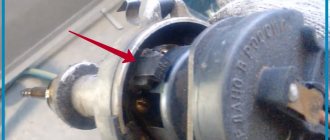
Here it is, the classic Toyota brake force regulator:
Regulator for cars with ABS
This is a regulator for cars with ABS. On cars without ABS, it is the same shape, but in the place where the yellow mark is in the photo, there is another outlet for the brake pipe (which is directly connected to the left input in the photo).
"Wizard" OR ABS?
And yet, such a regulator on a modern car is a legend of deep antiquity. It cannot compete with ABS, especially if the driver is an average driver who does not know extreme driving techniques. The curb weights of Kalina and Priora are almost the same - the difference is less than a percent. Using the same tires that were on the Kalina, the Priora with ABS showed the best results under any load. Moreover, no dosing of force on the brake pedal was required, you just press with all your heart, and the electronics do the rest.
Test results:
Adjusting the braking forces of Lada Vesta
The operating principle of the system that regulates and distributes brake fluid pressure on Lada Vesta cars is fundamentally different from previous models. The Lada Vesta brake pressure regulator is directly connected to the ABS system and is electronically regulated depending on the speed of each wheel.
The ABS control unit transmits signals from speed sensors and analyzes the situation. The electronics itself detects all faults and reports them to the driver using a special lamp on the dashboard.
How to adjust the VAZ distributor?
To ensure that the workload on the front and rear brake drives is distributed as correctly as possible, adjustments should be made periodically. Its principle is as follows. There is a gap between the end of the piston and the plate. It can range from two to three millimeters. However, the difficulty is that the gap size is imprecise. It is determined empirically. To make more precise adjustments of the brake force regulator, move the regulator along its bracket.
The clearance parameters should be selected depending on how the rear wheels behave in each case. If skidding of the rear axle wheels is not observed when braking, then the gap can be reduced. If the rear brakes engage earlier than the front brakes, then the gap should be increased.
Adjusting the “sorcerer” on “Logan”
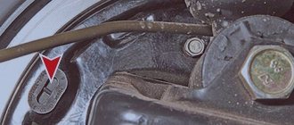
The brake force regulator on the Logan is located on the bottom between the front and rear axles.
To self-adjust, you need to clean the “sorcerer” and replace the lubricant in it. Then make half a turn with the adjusting nut. Then you can go for the test. If the rear pair of wheels does not brake, then tighten the nut again.
If the vehicle being tested does not have ABS, then even if you tighten the nut all the way, you may not achieve the result. Sometimes replacing the sorcerer can help, but this does not always save the situation. The fact is that in 9 out of 10 Logans without ABS, the regulator does not work at all. The reasons are a weak spring. And the owner has two options - change the springs to stiffer ones or install a rubber gasket to increase the pressure on the “sorcerer” mechanism.
Functions and purpose
The brake force regulator is used to automatically change the fluid pressure in the rear brake cylinders of a vehicle. In this case, adjustment is carried out according to the loads acting on the machine when the speed decreases. Such regulators are used in systems with pneumatic or hydraulic drive. It is necessary to change the cylinder pressure in order to prevent the rear wheels from completely locking. If they are blocked, the car will skid and the driver may lose control.
In some car models, in order to maintain controllability and stability, similar mechanisms-regulators are additionally used on the brake drives of the front wheels.
In addition, a brake force regulator is used to improve the efficiency of stopping an empty vehicle. When a car is not loaded, its grip on the road will be different from that of a loaded car. Therefore, it is very important to be sure to change the braking force on different axles. In passenger cars, static devices are used as regulators. Automatic solutions are installed in trucks.
In cars created for sports, another type of “sorcerer” is used. This is a screw regulator. What it is? It is located in the cabin, and with its help you can adjust the balance of the braking system directly during the race. Settings depend on the weather, track conditions, and tire conditions.
Regulator device on KamAZ vehicles
This unit consists of a valve, a valve pusher along with an actuator. The device also has a piston with an inclined rib, a membrane that is in connection with the piston. There are connecting tubes inside the housing. The adjuster channels attach to the top of the faucet, and a second channel connects to the brake chambers on the rear wheels. When the car slows down, air supplied from the top of the brake valve to the first channel of the regulator moves the piston down, and on the other side it is compressed until it stops. The valve is pressed against the pusher seat and the second channel at this moment is more connected to the atmosphere. Further movement of the piston will then cause the valve to open. Air from the first channel will flow into the second, and then to the brake chambers.
The MAZ brake force regulator has a similar device and operating principle.
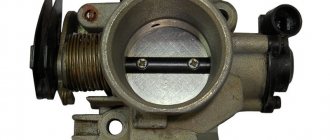
General view of the Hyundai Porter brake system
Hyundai Porter light commercial vehicles (as well as its “related” H-100 and Kia Bongo) use a number of technical solutions typical for passenger cars. This also applies to the truck’s braking system: the Porter has a dual-circuit braking system with a hydraulic drive and a vacuum booster, with front disc and rear drum brakes. The car also uses a component called a distributor valve (brake force regulator, popularly known as a “sorcerer”).
The Hyundai Porter brake system contains the following main parts: a brake pedal assembled into one unit with a master cylinder and a vacuum brake booster, a reservoir for storing brake fluid, front disc brakes, rear drum brakes, a brake force regulator, a supply piping system brake fluid to the brake mechanisms. Each component plays its role in the system.
Brake pedal, master cylinder and brake booster. This assembly is installed under the dashboard in the truck cab on a common bracket with the clutch pedal. The system is designed in such a way that the force from the brake pedal is transmitted to the vacuum booster, and from it to the main brake cylinder. The vacuum for the operation of the amplifier is taken from the diesel intake manifold and is supplied through a special tube. Brake fluid is transferred from the reservoir to the cylinder by two flexible hoses, and from the master cylinder to the wheel brake cylinders by two metal tubes.
Brake fluid reservoir. It is installed in the engine compartment using two bolts. The tank has a filler neck, fittings for connecting to the working fluid supply pipes to the main cylinder and a working fluid level sensor with a connector.
Front brake mechanisms. Disc type, have a standard design. A steel brake disc is installed on the wheel hub, which in the front part fits into a caliper (it is mounted on a brake shield fixed motionless on the wheel hub) with two pads. A special feature of the Hyundai Porter front brakes is the presence of two cylinders located in the caliper (and, accordingly, two pistons) that provide drive to the brake pads. The caliper has a fitting for connecting the brake pipe (brake fluid is supplied through it) and a fitting for bleeding the brake system. The car uses massive ventilated brake discs.
Rear brake mechanisms. Classic drum brake pads with internal brake pads. The semicircular pads, together with the brake cylinder (which has two pistons), the parking brake actuator and other parts, are mounted on the brake shield and covered with a cast-iron brake drum, which is mounted on the hub using five studs. These studs also serve to mount the rear wheel disc.
The brake force regulator should be described in more detail.
"Chevrolet Niva"
In the normal position of the regulator, as the vehicle's weight increases, its braking distance decreases - this affects the more complete use of the traction weight by the rear wheels.
The best braking is at full load, when the regulator minimally limits the pressure in the rear brakes.
But at partial load this is fraught with skidding. The high center of gravity and short wheelbase of the Shnivy contribute to a significant redistribution of mass during braking, therefore, at partial load, the contribution of the rear axle to braking is small.
How does the mechanism work?
It should be noted that the brake force regulator is not installed on cars with ABS, although the “sorcerer” is the ancestor of this system. It also helps protect the wheels from locking during braking.
In passenger cars, the “sorcerer” has a fairly simple device. It consists of three elements - the body, pistons, and valves.
The device body is internally divided into two cavities. The first cavity of the regulator is connected to the master cylinder (MC). The second is connected to the rear brake mechanisms. When emergency braking is necessary, the front of the car will tilt. With the help of pistons and valves, due to this tilt, the access of the working fluid to the brake cylinder will be blocked.
Thus, the VAZ brake force regulator automatically controls and distributes forces on the wheels of the rear axle. The car does not skid in the event of an emergency press on the pedal.
How to install a tee instead of a sorcerer
In the case of the VAZ 2106-07, you can simply remove the regulator; the tee is already installed in the system; the main line from the GTZ is simply connected to it.
- Using a special “10” wrench, unscrew the brake pipe fittings from the mechanism.
- Unscrew the tube coming from the brake adjuster from the rear brake hose.
Disconnect the sorcerer tube from the rear brake hose
- Disconnect the control lever from the axle and body. We take out the regulator assembly with the rod and throw it away.
- Carefully bend the brake pipe from the master cylinder to reduce its length. It should not dangle under the bottom of the car. We connect it to the brake hose of the rear brakes.
bend the brake pipe from the master cylinder to the rear brake hose
Now all the force from the main one goes through the tee to both rear brake cylinders. Therefore, deceleration will occur on both wheels simultaneously with the front ones.
Service
This part cannot be repaired. But in order for it to work properly, it needs to be maintained. This is usually done before making adjustments. The unit is installed in an unfavorable location - during operation it gets exposed to water, snow, dirt, and reagents from the road. All this makes the job worse. Gradually, water and snow become causes of corrosion.
General maintenance activities include cleaning the “sorcerer” from rust, removing the old rubber boot and installing a new one, replacing the lubricant, and cleaning all elements of the regulator from contamination. The old grease is first removed from under the boot.