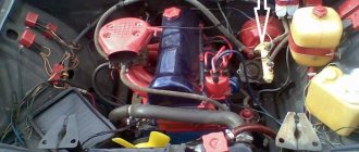
Troubleshooting
The first sign of loss of vacuum booster seal is not deterioration of the brakes, as many sources on the Internet describe the malfunction. When air just begins to leak through the leaky membrane, the VUT continues to function properly, since the motor manages to maintain a vacuum in the front chamber. The first symptom is changes in the operation of the engine itself:
- due to air leaks into the third cylinder, the engine begins to “trouble” at idle;
- crankshaft revolutions “float”, the stronger the suction, the greater the amplitude of oscillations;
- a running engine reacts to the brake pedal and stalls when pressed sharply;
- Gasoline consumption increases.
Air leaking into the engine through the VUT causes the third cylinder to turn off - the engine begins to “trouble.”
If the car owner ignores the primary symptoms, the situation gets worse - the pedal becomes harder and requires more physical effort to slow down and stop the car. The car can be used further; a breakdown of the VUT does not lead to a complete failure of the brakes, but it significantly complicates driving, especially if you are not used to it. Emergency braking will become a problem.
How to make sure that the vacuum booster is leaking:
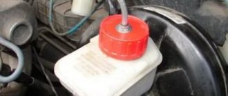
- Loosen the clamp and remove the vacuum pipe from the fitting on the manifold.
- Plug the fitting with a tight homemade plug.
- Start the engine. If the revs level out, the problem clearly lies in the amplifier.
- Remove the high voltage wire and remove the spark plug for cylinder III. If the VUT fails, the electrodes will be smoked with black soot.
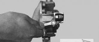
Whenever possible, I use the old “old-fashioned” method - I simply pinch the vacuum hose with pliers while the engine is running. If the third cylinder starts working and idle speed is restored, I proceed to checking the brake booster.
Similarly, the problem can be temporarily fixed while on the road. Disconnect the pipe, plug the fitting and calmly go to the garage or service station - the power unit will operate smoothly, without excessive fuel consumption. But remember, the brake pedal will become hard and stop responding instantly to light pressure.
Additional diagnostic methods:
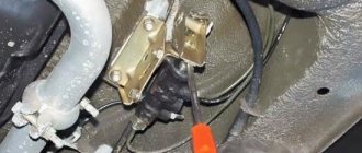
- Press the brake 3-4 times and start the engine while holding the pedal. If it does not fail, the valve has probably failed.
- With the engine not running, disconnect the hose from the fitting, remove the check valve and firmly insert a pre-compressed rubber bulb into the hole. On a sealed amplifier it will retain its shape, on a faulty amplifier it will fill with air.
Using a bulb, you can accurately determine the location of the defect, but the vacuum booster will have to be removed. While pumping air into the chamber, wash the edges of the joints and the stem seal - bubbles will indicate the location of damage.
How does it work
The principle of operation of the vacuum brake booster on the VAZ 2107 can be divided into three stages, each of which we will consider in detail.
The brake pedal is not pressed (initial state)
In this position, with the engine running, a vacuum is created in the vacuum chamber. The bypass valve is open, the atmospheric valve is closed. Through the bypass in both chambers of the vacuum amplifier, the pressure (vacuum) is equalized. Therefore, there is no impact on the diaphragm, or the master cylinder rod. The vehicle's brakes are not engaged.
If there is a pressure difference between the cavities of the vacuum body, then on the side where it is higher, it will press on the membrane, which in turn will press on the brake cylinder piston pusher. This impact will be minimal, but it will be enough for the brake pads to “bite” the brake mechanisms. The driver will not feel the slowdown, but the wear on the pads will increase.
Click on the picture to enlarge it
Press the brake pedal and release it
In this position, the pusher connected to the pedal assembly begins to move. Its movement closes the bypass valve and opens the air valve. Through it, air enters the air chamber from the atmosphere through the filter. An area with atmospheric pressure is created in it.
Since there are different pressures on both sides of the membrane - vacuum on one side, atmospheric pressure on the other, it begins to “press” on the membrane. It bends as the pusher moves towards the GTZ, thereby minimizing the driver’s effort that he must expend to push the brake pedal. The rod pushes the piston of the brake cylinder, the brake mechanisms of the wheels are activated and the car slows down.
Click on the picture to enlarge it
The driver releases the pedal. The force acting on the vacuum booster pusher stops. Under the action of the return spring, the brake cylinder rod returns to its original position. When both rods return, the atmospheric valve closes and the bypass valve opens. The pressure on different sides of the diaphragm is equalized (vacuum here and there) and it takes its initial position.
Click on the picture to enlarge it
Pedal lightly pressed
There are cases when a car owner keeps his foot on the brake pedal, but does not press it. This happens when he is preparing to brake, leading ahead to an obstacle or hole in the road, or simply putting it “just in case”, ready. This situation often happens to beginners who are tense behind the wheel. Fearing an accident, they keep their foot on the clutch, which leads to its breakdown, or press the brake.
As mentioned above, when you press the pedal, the pistons in the master brake cylinder begin to work, which means the pads “bite” the discs. Even a small force can trigger the system. The driver will not notice it, but the pads will be worn out by constant contact with the brake disc.
To avoid increased wear, the pedal has a free play that can be adjusted. In addition, the vacuum chamber has a rubber rod buffer that connects it to the pusher piston.
If the foot rests on the pedal, but does not press it, then due to the weight of the foot and shoe, free play is selected and the brakes are not applied. If the idle speed is not set correctly, then when you put your foot on the brake, the rod will begin to press down on the master cylinder piston. To prevent this from happening, a buffer is used. The pusher piston rests against it, on the other side it is supported by the “elasticity” of the brake fluid and return springs. To overcome this resistance, you need to push the pedal harder; the weight of your leg is not enough for this.
Click on the picture to enlarge it
Video of how a vacuum valve works in a car (without translation):
Advertising:
In finding the “right” brakes, you can’t do without adjusting the pusher rod.
Problems with brakes are quite a common occurrence among first-generation sports drivers, the reasons vary, but there is another one about which I have not seen anyone write about. About two years ago I changed the brake discs and caliper assemblies on the front wheels, since they were all pretty worn out and there was no desire to invest in repairs. Then I didn’t change it myself, but gave it to a repairman I knew. After the replacement I drove out and I remember I couldn’t be happier, the car braked just great. But the joy did not last long, at first it worsened, and then the rolling disappeared completely, in the end I had difficulty driving to work on the first one, the calipers jammed the discs. I called this friend, I know what the problem is, he came, removed the turbocharger, turned the rod and oops... I again found myself with nothing, or rather without brakes. Subsequently, independent adjustment of the self-priming mechanisms in the rear wheel drums with the replacement of the pads improved the situation, the car braked perfectly - one could say so if it did it the first time.) That is, for example, I’m driving and don’t touch the brake for a while, then Once, the first press of the floor, the car barely noticeably slows down, does not lead anywhere, and from the second and subsequent presses it slows down just fine. The only thing was that the pedal was always very soft, it grabbed in the middle and bottom of the pedal stroke. If you were driving in traffic jams, the brakes were generally excellent. I pumped it more than once, there was no air, the brake fluid did not leak, the pedal travel was normal, the vacuum cleaner was working, the GT was new (and there were no iron symptoms on it), I accelerated on packed snow, observers confirmed that all the wheels brake perfectly, I myself felt the car doesn't drive away. But the first press... During this time, I trained myself to imitate the work of the abs so cleverly that some abs might probably envy.)) But what the hell is this, I was haunted by the same thing as the tightening of the rod after the brakes jammed after installing new calipers. As a result, he returned to the roots, he is a manual. And there, in the section about “Removing, servicing and installing the master brake cylinder”, I saw about “Adjusting the length of the pusher rod”
Device
VAZ 2107 injector The VAZ 2107 injector consists of the following elements:
- Computer;
- Sensors;
- Fuel pipes and hoses;
- Fuel and air filter;
- Actuators;
- Gas tank;
- Wiring.
The injector power system contains the main element - a computer or ECU. Its permanent memory contains a program (algorithm) in accordance with which the control of actuators is implemented, these include:
- Fuel pump;
- Injectors;
- Idle air control;
- Canister valve.
Each of the above elements performs its own function.
Gasoline pump
Turned on by the ECU output signal through a relay. Has a strainer and fuel level sensor. The gasoline from it passes through the fuel filter. The pump is located in the tank and to remove it, you need to remove the back seat, remove the hatch and unscrew the fastener.
Nozzle
It is a sprayer equipped with a solenoid valve. Triggered by an ECU impulse. Accordingly, the duration of valve opening (the amount of gasoline supplied) depends on the time the pulse is applied. It is installed on a ramp common to all injectors, a constant pressure in which is maintained by a valve. If it is exceeded, the valve opens and gasoline returns back to the tank. The injector enters the intake manifold. The air flow, passing through the intake manifold, carries away a portion of gasoline ejected by the nozzle.
The structure of the VAZ 2107 fuel system
Idle speed control
The fuel system maintains engine idle speed using a regulator. It is a stepper motor connected to a conical shaped control body. Its approach reduces the air flow entering the intake manifold; its removal, on the contrary, increases it.
Canister valve
It is needed to turn on the ventilation of the adsorber, which accumulates gasoline vapors and releases them into the intake manifold at the right moment.
The following sensors are installed on the VAZ 2107:
- Crankshaft position;
- Mass air flow;
- Throttle position;
- Coolant temperature;
- Speed;
- Oxygen content in exhaust gases.
Crankshaft position
This parameter is needed by the ECU to open the injectors in a timely manner. If this sensor malfunctions, the VAZ 2107 will not drive.
Air flow
Allows you to supply fuel in the right quantity. The signal from this sensor is sometimes incorrect. The reason for this may be its malfunction caused by high humidity or low temperature. An air filter with condensation inside or dirty will adversely affect this sensor.
Coolant temperature
The parameter is needed so that the ECU understands whether the engine is warmed up. This is necessary for the correct operation of a cold motor. The mixture is enriched due to temperature correction.
Oxygen concentration
The oxygen content in the exhaust gases must be measured to adjust the composition of the fuel mixture. It doesn't work when it warms up. This is advisable because the mixture is enriched.
Vacuum brake booster: faults and repairs.
Vacuum brake booster: faults and repairs.
Operation and symptoms of malfunctions of the vacuum brake booster.
Drivers of the current generation do not remember the times when, when braking on a wet or slippery road, they had to press the brake pedal so hard that they stood up over the seat, tightly holding the steering wheel. These times are already a thing of the past; now there is a vacuum booster that helps you brake without straining. What is it, how does it work?
The mechanism of operation of the vacuum brake booster (VUT).
Elements of the vacuum brake booster.
The main components that make up the vacuum brake booster.
The vacuum brake booster (VUT) operates on this principle. This is a chamber, closed and round in shape; it is divided into two parts by a membrane. One part is connected by a hose to a vacuum. The second part has a monitoring valve that “monitors” the change from vacuum to atmospheric air. He doesn’t just “monitor”, he clearly regulates this shift.
The pedal is free and not pressed - the diaphragm is motionless. The pedal is pressed and the vacuum is now blocked by the valve, the diaphragm goes towards the brake cylinder and pushes the rod. This rod, no matter how stupid it sounds, increases the braking force! We press harder on the pedal, the hole becomes larger, more atmospheric pressure is released and the pressure on the brake cylinder increases. And this increase puts even more pressure on the brake pads. When extended, they completely block the wheels, and the car comes to a complete stop. That is, the vacuum brake booster (VUT) not only increases the braking force, it also increases the pressure force, so braking is more reliable!
Signs of a malfunctioning vacuum brake booster (VBR):
A malfunction of the vacuum brake booster also belongs to the next list of brake system malfunctions, but it will not lead to fatal breakdowns or situations, but it will spoil your nerves. Therefore, if suddenly difficulties with braking begin, or you have to make a lot of effort to do this, we check the VUT for malfunctions. This can be easily done at home (or rather in the garage), without the help of service station specialists.
Signs of manifestation:
• The engine starts to “sputter” at idle. We press the brake pedal - the “triple” has disappeared, which means the VUT is faulty.
• The engine is not running, pump the brake pedal a few times, then fix it (the pedal) in the middle of its stroke. Start the engine and see if the pedal has “failed”. If it goes to the floor, everything is fine with the VUT; if it remains in place, then your amplifier requires replacement or repair.
Diagnostic examination:
• Make a visual inspection. If there are even small leaks on the VUT body, urgently begin its “resuscitation” and first thoroughly check all the hoses and clamps. Sometimes all you need to do is tighten the clamps and everything will go back to normal.
If, through self-diagnosis, you find out that your VUT needs replacement or repair, there are two options:
The first of them is to go to a service station and entrust the car to specialists.
The second option is to go to a car store, buy a repair kit that matches your model, and replace it yourself. There is no need to talk about the first option - everyone knows it. But now we’ll tell you what to do with the second option!
Here are all the steps to repair (replace) a vacuum brake booster (VUT):
Repair the brake system vacuum booster using a repair kit.
1. We read the “master book” of your car - the manual of your car in order to clarify the design of the VUT and recommendations for its repair.
2. Under the steering shaft, disconnect the VUT drive rod from the brake pedal.
3. Remove the brake master cylinder (GTC) under the hood compartment.
4. Disconnect the vacuum hose from the check valve.
5. We either repair our old VUT (if we can), or install a completely new VUT.
6. We check our work by moving downhill and pressing the pedal first lightly and then harder. The effect will be on your face!
A vacuum brake booster makes not only braking easier, but also life, because it provides additional safety. Check it periodically, change and repair as necessary and good luck on the roads!
Tuning the brake system of VAZ-2106
The brake system of a car is the main mechanism responsible for safety on the road. The manufacturer produces cars with a braking system that fully meets all the technical characteristics of the vehicle.
The braking system in the VAZ 2106 is not the strong point of this car, but it can be improved
The exception to the rule is domestic cars that were developed and produced several decades ago. Their braking system does not quite meet modern technological requirements, which is pushing VAZ owners to make drastic decisions. Increasingly, they are improving and modernizing the braking system of vehicles. In this article we will look at how to properly tune the VAZ-2106 brakes in order to improve their performance and safety during vehicle operation.
Modernization of the master cylinder and replacement of the vacuum brake booster of VAZ-2106
The brake system of the VAZ-2106 is not of particular quality. Let's look at how to upgrade the brakes of the six in order to maximize the quality of braking of the car.
Heavy pressing of the brake pedal and an increase in the braking distance of the car may be indicators of incorrect operation of the vacuum booster, which is one of the main operating mechanisms of the brakes. The serviceability of the unit is checked in the car with the engine turned off.
Brake pedal: 1 — vacuum booster; 2 - pusher; 3 — brake pedal; 4 — brake light switch buffer; 5 — switch nut; 6 — brake light switch; 7 — pedal release spring; 8 – main cylinder
Let's look further at how to check the vacuum brake booster. To do this, you need to press the brake pedal five or six times and then start the engine. If the pedal moves forward a little, then the amplifier is working correctly. Otherwise, you need to look for the cause of the malfunction. This could be poorly tightened clamps or fasteners, or a rupture in the hose connecting to the engine intake manifold. If the hose is not damaged and after tightening the fasteners and clamps the problem does not go away, then the fault is in the amplifier itself.
Most often, the VAZ-2106 vacuum brake booster is not repaired, but replaced with a new product. In order to remove the booster, you must first remove the brake master cylinder. It also needs to be replaced with a larger volume product. The standard cylinder of the car cannot cope with the formation of the required pressure in the brake system.
The amplifier fastening elements are located on the driver's side under the mat and carpet. First you need to unscrew the four bolts, and then use a flat-head screwdriver to pull out the lock washer and rod that connect the pedal and the power steering linkage. There are no additional fasteners on the side of the engine compartment, so the amplifier can be pulled out and replaced with a new product. Everything is assembled in the same way in reverse order. During assembly, special attention should be paid to the integrity of all rubber hoses and pipes. It is important to tighten the fasteners to the maximum, as they are responsible for braking efficiency. After installing the VUT, it is important to adjust it correctly, adjust the length of the rod or free play of the pedal. The length of the rod is adjusted using a bolt located on the vacuum booster. Ideally, it should rise 7.1 millimeters above the amplifier. If the bolt is tightened further, then the pedal will not return to its standard position after pressing. The fact that the screw is tightened is weakly indicated by pressing the pedal hard. It is important to find the timing of the valves by adjusting the stem.
The most correct option would be to carry out a comprehensive replacement of the amplifier and cylinder. Experts advise, instead of classic spare parts, to purchase a nine-inch VUT assembly from Niva 21214 along with an enlarged master cylinder. And also for installation, a bracket from the same car model is purchased. The reinforced VUT and cylinder can be installed on the VAZ-2106 without modifications to the fasteners.
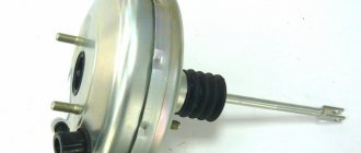
How to check when purchasing
Before purchasing a new spare part, its quality can be assessed visually - there should be no obvious damage to the elements: body, boots, casings, protruding parts of the pusher and rod. If it is sold with a fitting and a check valve, then we check it for leaks (valve). To do this, you need to blow into the fitting from the hose connection side; if air does not come out on the other side, then the valve is working. You can also use a rubber bulb - squeeze the air out of it, insert it into the fitting on the vacuum connection side; if the bulb remains compressed, the valve holds.
In the same way we check the mechanism itself. For this you will need a soap solution and compressed air. We carry out this test in a garage environment, so after purchasing an amplifier, be sure to take a receipt from the store so that you can return it if it is found to be faulty.
In the garage we wash the place where the two halves of the mechanism are rolled, the boots, the cuffs, all the places where there may be air leaks. We take out the fitting. We direct compressed air from the compressor into the resulting hole and observe. Where bubbles appear, the seal is broken, the vacuum amplifier is defective.
Absolute vehicle malfunctions
During operation, the braking functions of the system deteriorate. This is due to wear and tear of components, assemblies and parts that require repair. Some vehicle malfunctions are included in a special “List...”, and driving with them is prohibited.
Inefficiency of the working vehicle
The most common malfunction of the brake system (including the VAZ-2107) is inefficiency, which is diagnosed by two main parameters (when carrying out a specialized instrumental study):
- increasing braking distance;
- increase in steady deceleration during braking.
Such faults can be determined by eye. After driving a passenger car on a dry road at a speed of 40 km/h, when braking, the car travels a distance exceeding 12.2 m. In this case, according to paragraph 2.3.1 of the traffic rules, the use of the vehicle is prohibited (even to the parking or repair site) . This malfunction may be due to:
- presence of air in the system;
- fluid leakage from the system;
- worn out pads;
- failure of the main or wheel cylinders.
In other words, almost the entire vehicle should be subject to monitoring. Repair (replacement) of components and assemblies will require bleeding the system to remove air from it.
Leakage of the working vehicle
During vehicle operation, components, assemblies and parts are subject to wear, which leads to depressurization of the system and leakage of brake fluid. This most often occurs in brake hoses or wheel cylinders. Fault repair is carried out by monitoring leaks and replacing damaged elements.
Leakage of the system also excludes the possibility of operating the car (according to paragraph 2.3.1 of the traffic rules).
Ineffective parking vehicle
This defect is the most common when the car moves involuntarily even with the handbrake locked. This is due to wear on the pads, discs or drums, as well as stretching of the cable elements.
According to the requirements of the “List...”, a parked vehicle must ensure that the passenger car is stationary:
- on a slope of up to 16% at full load;
- on a 23% slope when equipped.
In the event that these requirements are not met, the vehicle can only be driven to a parking or repair site. Repair of the malfunction is ensured by adjusting the cable tension with a special nut or replacing worn parts.
CHECKING AND ADJUSTING THE BRAKES
Checking pipelines and connections
To prevent sudden failure of the brake system, carefully check the condition of all pipelines and connections, paying attention to the following:
– metal pipelines should not have nicks, scratches, burrs, active foci of corrosion and should be located away from sharp edges that could damage them;
– brake hoses must not have any cracks on the outer shell or signs of chafing visible to the naked eye; they should not be exposed to mineral oils and lubricants that dissolve rubber; by pressing the brake pedal firmly, check to see if any swelling appears on the hoses, indicating their destruction;
– all pipeline fastening brackets must be intact and well secured; loosening or destruction of brackets leads to vibration of pipelines, causing their breakdowns;
– do not allow fluid to leak from the connections of the master cylinder with the tank and pipelines; if necessary, replace the tank bushings and tighten the nuts without subjecting the pipelines to deformation.
When tightening the pipeline nuts, use wrench 67.7812.9525.
Eliminate any detected faults by replacing damaged parts with new ones.
Flexible hoses, regardless of their condition, should be replaced with new ones after 125,000 km or after five years of vehicle operation to prevent sudden ruptures due to aging.
Checking the functionality of the vacuum booster
Rice. 6–2. Vacuum booster: 1 – vacuum booster housing; 2 – amplifier housing cup; 3 – rod; 4 – adjusting bolt; 5 – rod seal; 6 – sealing ring of the master cylinder flange; 7 – diaphragm return spring; 8 – amplifier pin;
9 – tip mounting flange; 10 – valve; 11 – hose tip; 12 – diaphragm;
13 – amplifier housing cover; 14 – sealing cover; 15 – piston; 16 – protective cover of the valve body; 17 – air filter;
18 – pusher; 19 – pusher return spring; 20 – valve spring; 21 – valve; 22 – valve body bushing; 23 – rod buffer; 24 – valve body; A – vacuum chamber; B – atmospheric chamber; C, D – channels
Press the brake pedal 5-6 times with the engine off to create equal pressure close to atmospheric in cavities A and B (see Fig. 6-2). At the same time, by the force applied to the pedal, determine whether the valve body is jammed.
Keep the brake pedal depressed and start the engine. If the vacuum booster is working properly, the brake pedal should “move forward” after starting the engine.
If the brake pedal does not “go forward”, check the fastening of the hose tip, the condition and fastening of the tip flange in the booster, the hose to the tip and the fitting of the engine intake pipe, since loosening or damage to them sharply reduces the vacuum in cavity A and the efficiency of the booster.
Adjusting the brake drive
Rice. 6–11. Brake drive: 1 – master cylinder; 2 – tank; 3 – vacuum booster; 4 – brake pedal bracket; 5 – brake light switch buffer; 6 – brake light fastening nut; 7 – brake light switch; 8 – brake pedal
The free play of the brake pedal when the engine is not running should be 3–5 mm. The adjustment is carried out by moving the brake light switch 7 (Fig. 6–11) with nut 6 released. Install the switch so that its buffer rests against the pedal stop, and the free play of the pedal is 3–5 mm. In this position of the switch, tighten nut 6.
Adjust the brake pedal free play when the engine is not running.
If the brake light switch is too close to the pedal, it will not return to its original position. In this case, valve 21 (see Fig. 6–2), pressing against body 24, separates cavities A and B, which opens air access to chamber B, and the wheels are incompletely released when the pedal is released.
If moving the brake light switch cannot eliminate incomplete release of the brake mechanisms, then disconnect the brake master cylinder from the vacuum booster and check the protrusion of adjusting bolt 4 relative to the mounting plane of the master cylinder flange (size 1.25–0.2 mm). This size can be set by holding the end of the rod with a special wrench and tightening or unscrewing bolt 4 with another wrench.
Adjusting the parking brake system
If the parking brake system does not hold the vehicle on a 25% grade when moving the lever 2–8 teeth of the sector, adjust the system in the following order:
Rice. 6–9. Parking brake system drive: 1 – lever fixation button; 2 – parking brake drive lever; 3 – protective cover; 4 – traction; 5 – cable equalizer; 6 – adjusting nut; 7 – lock nut; 8 – cable;
9 – cable sheath
– loosen the lock nut 7 (see Fig. 6–9) of the tension device and tighten the cable by tightening the adjusting nut 6;
– check the full stroke of lever 2, which should be 2–4 teeth per sector, then tighten the lock nut.
After performing several brakes, make sure that the stroke of the lever has not changed and the wheels rotate freely, without sticking when lever 2 is completely lowered.
Checking the functionality of the pressure regulator on the car
Place the car on a lift or inspection ditch, clean the pressure regulator and its drive parts from dirt.
Rice. 6–3. Pressure regulator drive: 1 – pressure regulator; 2, 16 – pressure regulator mounting bolts;
3 – bracket for the pressure regulator drive lever; 4 – pin; 5 – pressure regulator drive lever; 6 – axis of the pressure regulator drive lever; 7 – lever spring; 8 – body bracket; 9 – pressure regulator mounting bracket;
10 – elastic lever of the pressure regulator drive; 11 – earring; 12 – earring bracket; 13 – washer; 14 – retaining ring; 15 – bracket pin; A, B, C – holes
Rice. 6–4. Pressure regulator: 1 – pressure regulator body;
2 – piston; 3 – protective cap; 4, 8 – retaining rings; 5 – piston sleeve; 6 – piston spring; 7 – body bushing; 9, 22 – support washers; 10 – sealing rings of the pusher; 11 – support plate; 12 – pusher bushing spring; 13 – valve seat sealing ring;
14 – valve seat; 15 – sealing gasket; 16 – plug;
17 – valve spring; 18 – valve; 19 – pusher bushing; 20 – pusher; 21 – piston head seal; 23 – piston rod seal;
24 – plug; A, D – chambers connected to the main cylinder;
B, C – chambers connected to the wheel cylinders of the rear brakes; K, M, N – gaps
By external inspection, make sure that the pressure regulator and its drive parts are not damaged, there is no leakage of brake fluid, plug 24 (see Fig. 6–4) is recessed into the housing hole by 1–2 mm, there is no play in the connection of the earring 11 (see Fig. Fig. 6–3) with elastic lever 10 and bracket pin 15.
Have an assistant press the brake pedal. Piston 2 (see Fig. 6–4) should extend from the housing by 1.6–2.4 mm, compressing leaf spring 7 (see Fig. 6–3) until it stops against lever 5. Lever 5, overcoming the force from the elastic lever 10, it will rotate relative to the pin 4.
Non-compliance with the listed requirements, lack of piston stroke, as well as its insufficient or excessive stroke indicates a malfunction of the regulator or its drive. In this case, repair or replace the pressure regulator, and after installing it, adjust its drive (see chapter “Checking and adjusting the pressure regulator drive”).
Removing air from the hydraulic drive
Bleeding the brakes is necessary to remove air from the hydraulic drive, which significantly reduces the effectiveness of the service brake system. Air can enter the hydraulic drive due to depressurization of the system during repair or replacement of individual components, as well as when replacing brake fluid. The presence of air in the brake drive is indicated by increased travel of the brake pedal and its “softness”.
Before removing air from the brake system, make sure that all brake drive units and their connections are tight, clean the cover and the surface around the reservoir cover, fill the reservoir with Rosa fluid up to the “MAX” mark with the cover removed. Then thoroughly clean the bleeder fittings and remove their protective caps.
It is not recommended to use fluid drained from the system to fill the reservoir, as it is saturated with air, has a lot of moisture and may be contaminated.
Air from the system is removed first from one circuit, then from the other, starting with the rear brake wheel cylinders.
Rice. 6–12. Removing air from the hydraulic brake drive: 1 – bleeder fitting; 2 – hose;
3 – vessel with liquid
Place a rubber hose 2 onto the head of fitting 1 (Fig. 6–12) to drain the liquid, and lower its free end into a transparent vessel 3, partially filled with liquid.
Pressing the brake pedal sharply 3–5 times at intervals of 2–3 s, unscrew the fitting 1/2–3/4 turn while the pedal is pressed. Continuing to press the pedal, displace the liquid in the system along with the air through the hose into the container. After the brake pedal reaches the forward extreme position and the flow of fluid through the hose stops, tighten the air release fitting as far as it will go. Repeat these operations until bubbles stop coming out of the hose.
Keeping the pedal pressed, tighten the fitting as far as it will go and remove the hose. Wipe the fitting dry and put on the protective cap.
Repeat the operations for other wheels, first on the second wheel of the same circuit, and then sequentially on both wheels of the other circuit.
When removing air, make sure that there is liquid in the tank, avoiding exposing its bottom, as this will allow air to enter the system again.
If there is no air in the brake drive, the brake pedal should go through 1/2 of its full travel.
To eliminate the influence of the vacuum booster on bleeding the brakes, remove air with the engine not running.
If there is no brake fluid in the hydraulic drive, fill the system as follows:
– fill the brake fluid into the master cylinder reservoir;
– unscrew the fittings on the cylinders of all wheels by 1.5–2 turns;
– pressing the brake pedal sharply and releasing it smoothly, tighten the fittings as liquid flows out of them. Then bleed the system.
When bleeding air on a car whose brake system has been in operation for a long time, replace the fluid in the system with new one.
Replacing brake fluid
To ensure that no air gets into the hydraulic drive system when replacing the brake fluid and that a minimum amount of time is spent on this operation, adhere to the following rules:
– proceed in the same order as when bleeding the brakes, but use a hose with a glass tube at the end, which is lowered into a container with brake fluid;
– while pressing the brake pedal, pump out the old brake fluid until new fluid appears in the tube; then make two full strokes with the brake pedal and, holding it pressed, tighten the fitting. When pumping, monitor the fluid level in the tank and promptly add fluid to the maximum level;
– repeat the same operation on each working cylinder in the same order as when bleeding;
– fill the reservoir to the maximum level and check the operation of the brakes while the car is moving.
How to check on a car
Method 1
With the engine off, press the brake pedal several times. With each press you will feel an increase in the force applied to the pedal. On the fifth press, fix your foot on the brake in the pressed position. We start the engine, it should fall a little. The force with which you press should decrease and the leg will “sag” a little.
If this happens, then everything is fine, the amplifier is working. Because with each press the vacuum in the chamber decreases, you have to press the pedal harder to push it completely. Having started the engine, air is sucked out of the chamber by the intake manifold through a hose, a vacuum is formed, the vacuum unit begins to work, and feels relief when the pedal is held down. Under the influence of the efforts of the leg, it “fails”.
Method 2
We started the engine, let it run for a minute and turned it off. We hit the brakes. If at the first press it, as it should, easily “falls” all the way, and with subsequent presses it becomes more and more difficult to push it all the way, then the amplifier is working.
Having turned off the internal combustion engine, the check valve closes, maintaining a vacuum in the amplifier chamber. The first time you press it, it engages the diaphragm and you press the pedal with ease. With subsequent presses, the pressure in the chambers is equalized, you need to make more efforts to “drown” the pedal all the way.
Method 3
With the engine running, press the brake. Keep the pedal pressed and turn off the engine. Without removing your foot, you will feel that the pedal begins to resist your pressing more and more every minute, which means that there is an air intake, the vacuum seal is not working properly.
In this case, it is not the tightness of the mechanism elements that equalizes the pressure in the chambers, and since there is no source of vacuum, the engine does not work, the system tries to push the rod to its original position. You feel an increase in pressure on your leg. To keep the pedal in the fully depressed position, you need to press harder on it.
Video on how to independently check the vacuum booster on a Lada:
After such checks, you need to remove the part from the car and replace it with a new one. How to do this - read below.
How to adjust the brake system on a VAZ 2110
In theory, the parking system should be able to hold the VAZ 2110 when the surface is tilted up to 25%. If it can’t cope, don’t rush to a car repair shop, where you’ll have to shell out a hefty sum - you can provide first aid to your car yourself:
- The tensioner locknut must be loosened.
- Then we tighten the cable.
- We check the full stroke of the lever (it should be 2-4 teeth per sector).
- Tighten the locknut more tightly.
- To be on the safe side, we perform several brakes, checking at the same time whether the stroke of the lever has changed.
In this simple way you can check how well the vacuum brake booster works on a VAZ 2110.
The wheels should rotate without effort, with the lever fully lowered.
Source
Caliper device
Let's move on. The front axle mechanisms are disk ones, consisting of calipers with the main brake elements - pads, and brake discs.
A caliper is a body with cylinders made in it for the pistons. This model has two of them, one for each block. The support structure is shown in the figure.
The caliper pistons have the form of a glass, which is placed in their cylinders, but they can move along it. To prevent fluid leakage, the pistons are equipped with o-rings.
Pads are small metal plates onto which linings made of friction material are glued.
The brake disc is made of metal for better adhesion to the surface of the pads; its side surfaces are well processed so that there are no protrusions or shells on them.
The VAZ 2107 brakes work like this: the fluid moves into the caliper cylinders, where it begins to push out the pistons. They come out of the cylinders, pressing the pads against the disc.
How to check the vacuum brake booster
A logical question arises: how to determine whether the vacuum brake booster is faulty. In fact, this is quite simple to do, and without the use of additional equipment, the test can be performed in a garage or even on the street.
The simplest check is performed using the following algorithm:
- With the engine off, it is necessary to pump up the vacuum booster (brake system). This is done by pressing the brake pedal about 4...5 times.
- At the end of the last press, the pedal must be locked in the pressed position.
- Start the engine at idle speed.
- If the “vacuum reservoir” is working properly, then when the engine starts, a vacuum will immediately enter it, as a result of which the brake pedal will move down a little, which will be clearly felt when your foot is placed on it.
- Accordingly, if the pedal does not move and does not respond to starting the engine, then there is a depressurization in the system.
It makes sense to perform another check if the brake system seems to be working properly, but when you press the brake pedal, a change in the operating mode of the internal combustion engine is observed. So, the check is performed according to the following algorithm:
Disconnect the pipe from the intake manifold.
- Its fitting must be hermetically sealed. To do this, you can use a clamp or a tightened rubber tube with a clamp.
- Start the engine and let it warm up a little.
- Press the brake pedal several times.
- If, at the moment of pressing the corresponding pedal, no changes occurred in the engine operating mode (its speed did not increase or decrease), it means that there is depressurization in the vacuum brake booster system.
- Accordingly, if the engine begins to “choke” when you press the pedal, it means that the “vacuum reservoir” and its system are working normally.
Please note that the described check must be carried out with the car stationary, since in this mode the vacuum brake booster will not work with all the ensuing consequences.
If the check reveals the presence of depressurization, then the next step is to localize the location of the damage. This is not always easy to do, since the crack or leak can be very small and sometimes located in the most unexpected places. However, as a check and preventative measure, it is necessary to check the following elements of the vacuum booster system:
- tightening and general condition of VUT pipeline clamps;
- VUT sealing tube at the clamping points and along the entire length (if possible), often the cause of depressurization is the appearance of a crack in the said tube;
- condition of the vacuum booster check valve seal, this is also a common cause, especially on older cars (for example, VAZ classic).
If the check does not produce results, then it makes sense to simply replace all the vacuum booster tubes with clamps.
Check valve
You can check the VUT check valve using one of two methods. The first of them involves dismantling the specified element, and the second involves holding the brake pedal with the engine running.
How to check a removed brake booster
After the valve is removed, you just need to blow into the fitting that was connected to the amplifier with your mouth or using an air compressor. If the valve is working properly, then air should flow freely. The next step in this case is to draw air from that fitting. Best by mouth. Accordingly, the valve should not let air back in. Otherwise, the check valve is partially or completely damaged and must be replaced. Instead of a mouth, you can use a thick rubber bulb, for example, from a hydrometer.
However, removing the check valve is not the best solution, since the process of removing it can damage the seal of the vacuum brake booster system. It is better to check the brake booster check valve on a car in the simplest way. In accordance with the second verification method, it is recommended to proceed as follows:
- start the engine and let it run for about one to two minutes;
- press the brake pedal all the way and turn off the engine;
- if the check valve is working properly, it will close, since there is no vacuum on the side of the manifold, and a vacuum will remain in the chamber, accordingly, the pedal will not press up (there will be no need to exert additional force to hold it);
- otherwise (if the pedal is pulled up sharply), the VUT check valve is damaged.
As in the case of a pipeline, it is easier and faster to replace the check valve with a new one, since this unit is usually non-removable and cannot be repaired, and its price is relatively low.
Removing the vacuum booster 2106-07
Removing the VUT on a VAZ classic car is quite simple, and if you have minimal plumbing skills, this work is not difficult to complete. We remove the unit as follows:
- we turn off the engine, disconnect the main brake cylinder (GTC) from the “vacuum chamber”, the cylinder is held on by two nuts. There is no need to disconnect the brake pipes and hoses from the turbocharger; we simply move the cylinder to the side;
- we pull the hose off the check valve, while holding the valve so as not to pull it out and break it;
- in the cabin, remove the fixing bracket on the brake pedal and release the VUT pusher;
- then in the cabin we unscrew the four nuts that hold the “vacuum unit”, dismantle the unit - it is removed in the engine compartment.
Rear brakes
On Zhiguli of the classic 2107 family and others, a drum brake system is used. Because its installation is explained by savings and a reduction in the overall cost of the machine. Moreover, the VAZ of previous years did not have high speeds, so installing rear disc brakes was not advisable, although their efficiency is higher.
Design
- Drum. It consists of two parts: the first is mounted on the axle (fixed), the second is on the hub and rotates with the wheel
- Brake pads
- Brake slave cylinder
- Tension springs
- Spacer plate
- Parking brake lever
Principle of operation
To fully activate the rear brakes, the driver needs to press harder on the pedal. In this case, the second piston of the GTZ starts working and another brake circuit is activated, which is responsible for transmitting force to the brake mechanisms of the rear wheels.
The pressure in the working cylinder (there is only one) pushes the pistons, which are located on the sides, apart. They rest against the brake pads, spreading their upper part to the side. The pads are seated on support posts. They can turn on them and move left or right. That is, the upper part moves to the side, the lower part, turning on them, tries to come together. But, the lower edges of the pads rest against the rivets, the force of the pistons moves them on the support posts towards the drum cover, and they evenly adhere with their entire surface to the moving part of the drum, which is connected to the wheel and, under the influence of friction, the rear axle slows down.
By releasing the pedal, the pressure in the brake line and cylinder decreases. The pistons return to their original positions (recessed inside), and the pads, under the action of return springs, converge, moving away from the drum cover. These springs do not allow the pads to move spontaneously, braking the hub.
Video of how the rear brakes work on the “seven”:
Malfunctions
The “sores” are the same as those of the front brake system. Due to the design features, new ones are added to them.
- Broken or stretched pressure springs. In this case, the rear axle will spontaneously begin to brake.
- Cracks, chips on the inside of the drum. Dirt can accumulate on it, rust can form, which can jam the wheels, although the pads will be brought together, since there is a miniature gap between them and the drum cover
What is VUT and why is it needed?
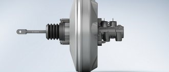
To determine the malfunction of the VUT, it makes sense to describe its purpose, operating principle, as well as the effect of the vacuum booster on engine operation. So, the main task of the “vacuum man” is to increase the physical force (usually 3...5 times) applied by the driver to the car’s brake pedal. This is vital because even a very strong person is not able to create enough force in the hydraulic brake system so that all the brake pads are compressed to the required value at the critical moment. This force is created due to rarefaction of air, and the area in the engine intake manifold is used as its source or is pumped by an additional pump.
Structurally, the VUT consists of two chambers - atmospheric (on the driver’s side) and vacuum (on the engine side). The vacuum chamber is connected to the intake manifold using an appropriate pipeline. When you press the brake pedal, the vacuum chamber is connected to the atmospheric chamber using a pusher, which has a so-called tracking valve. Next, the diaphragm is connected to the rod and brake fluid is pumped to the brake cylinders. If there is no force on the brake pedal, then under the influence of the return spring the diaphragm returns to its place, the pressure on the brake fluid weakens, which is why the brake pads move apart and braking stops.
In the simplest case, the vacuum brake booster takes vacuum from the intake manifold. To do this, it is connected to it by an appropriate pipeline. However, in many modern cars there are separate vacuum pumps for the vacuum pump. They come in two types. The first is mechanical, it is driven by the engine camshaft. The second is electric and is driven by a separate electric motor. The use of additional pumps not only increases the comfort of using the braking system, but also increases its reliability (for example, in the event of damage and/or depressurization). But still, the pump is only an auxiliary element, and the main vacuum is taken from the intake manifold.
Troubleshooting
The first sign of loss of vacuum booster seal is not deterioration of the brakes, as many sources on the Internet describe the malfunction. When air just begins to leak through the leaky membrane, the VUT continues to function properly, since the motor manages to maintain a vacuum in the front chamber. The first symptom is changes in the operation of the engine itself:
- due to air leaks into the third cylinder, the engine begins to “trouble” at idle;
- crankshaft revolutions “float”, the stronger the suction, the greater the amplitude of oscillations;
- a running engine reacts to the brake pedal and stalls when pressed sharply;
- Gasoline consumption increases.
Air leaking into the engine through the VUT causes the third cylinder to turn off - the engine begins to “trouble.”
If the car owner ignores the primary symptoms, the situation gets worse - the pedal becomes harder and requires more physical effort to slow down and stop the car. The car can be used further; a breakdown of the VUT does not lead to a complete failure of the brakes, but it significantly complicates driving, especially if you are not used to it. Emergency braking will become a problem.
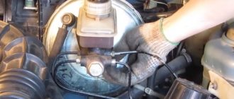
How to make sure that the vacuum booster is leaking:
- Loosen the clamp and remove the vacuum pipe from the fitting on the manifold.
- Plug the fitting with a tight homemade plug.
- Start the engine. If the revs level out, the problem clearly lies in the amplifier.
- Remove the high voltage wire and remove the spark plug for cylinder III.
If the VUT fails, the electrodes will be smoked with black soot. If soot is observed on the spark plug of cylinder III, and the remaining spark plugs are clean, you need to check the condition of the vacuum brake booster
Whenever possible, I use the old “old-fashioned” method - I simply pinch the vacuum hose with pliers while the engine is running. If the third cylinder starts working and idle speed is restored, I proceed to checking the brake booster.
Similarly, the problem can be temporarily fixed while on the road. Disconnect the pipe, plug the fitting and calmly go to the garage or service station - the power unit will operate smoothly, without excessive fuel consumption. But remember, the brake pedal will become hard and stop responding instantly to light pressure.
Additional diagnostic methods:
- Press the brake 3-4 times and start the engine while holding the pedal. If it does not fail, the valve has probably failed.
- With the engine not running, disconnect the hose from the fitting, remove the check valve and firmly insert a pre-compressed rubber bulb into the hole.
On a sealed amplifier it will retain its shape, on a faulty amplifier it will fill with air. To check the tightness of the amplifier and the functionality of the check valve, you can use a rubber bulb
Using a bulb, you can accurately determine the location of the defect, but the vacuum booster will have to be removed. While pumping air into the chamber, wash the edges of the joints and the stem seal - bubbles will indicate the location of damage.
GTZ VAZ 2110 signs of malfunction, purpose of the device, performance check replacement
Despite the fact that these two units are inextricably linked with each other, in our material we will consider them separately.
This will allow you to understand in detail all the nuances and features of the operation and repair of the two devices. I – main cylinder body; 2 – low pressure sealing ring; 3 – drive piston of the “left front-right rear brake” circuit; 4 – spacer ring; 5 – high pressure sealing ring; 6 – pressure spring of the sealing ring;
7 – spring plate; 8 – piston return spring; 9 – washer; 10 – locking screw;
II – drive piston of the “right front-left rear brake” circuit; 12 – connecting sleeve; 13 – tank; 14 – brake fluid emergency level sensor; A – gap
Vacuum booster
The braking system of a car certainly cannot be called perfect, so it has to be supplemented with devices that help improve efficiency. One of them is a vacuum booster.
Application and purpose
Today, a vacuum amplifier is in great demand because it is highly efficient.
Its tasks are extensive, but the amplifier copes with them all perfectly:
- The degree of resistance of the brake pedal increases;
- Reduces the load on the brake system;
- Acts as a highly efficient auxiliary unit;
- Has a positive effect on the service life of the brake system, etc.
This element has the following components:
- Dense body, for the manufacture of which a high-strength polymer is used;
- The diaphragm, which is also called the collecting node;
- Monitoring or control specialized valve;
- Pusher. It allows you to return the engine elements to their original position when there is no power;
- Main piston rod of the brake system cylinder (main);
- Switch return spring.
The body of this spring has two cellular divisions, which are divided into vacuum and atmospheric. Cells are often called chambers.
- The vacuum chamber is a cell directly connected to the brake master cylinder.
- The atmospheric chamber is a cell located opposite the brake pedal. Its open part of the body rests on the brake pedal.
It is also worth noting the diaphragm, which performs two very important tasks:
- Corrects the position of the piston in space;
- Pumps brake fluid to the main brake cylinders.
Installing a vacuum booster involves a serious change in the sensitivity of the pedal, so it is strongly recommended not to apply a large and sudden force to it in the “first couple”. Pressing should be done carefully and smoothly.
Malfunctions and ways to check them
It is possible that you may need to replace the vacuum booster on your VAZ 2110. The cause may be various malfunctions, the characteristic symptoms of which are as follows:
- When you press the brake pedal, a hissing noise occurs, and at the same time, the engine speed often increases;
- The car starts to shake;
- Spark plugs stop working efficiently;
- Fuel consumption increases noticeably.
Before replacing the vacuum booster on a VAZ 2110, it should be checked.
This procedure is performed as follows:
- As with normal bleeding of brakes, with the engine not running, press the gas pedal several times;
- After 5 or 6 presses, keep the pedal in the down position, resting it on the floor, and start the engine;
- After starting, the pedal itself will move forward a little.
There is also a high probability of damage to the diaphragm, on which a hole is formed over time. You can purchase the diaphragm with a repair kit, the cost of which is no more than 500 rubles.
Replacement
To replace an element, you need to understand the main issue - how to remove the vacuum booster from a VAZ 2110. Directly replacing the old element with a new one will not be difficult, just like the reassembly process.
Therefore, we will tell you about the main thing - dismantling the amplifier. Let's start with the fact that the procedure is not complicated, but it requires accuracy and sequence of steps. If you follow the recommendations, the work will take little time and will not take much effort.
- Disconnect the block with wires, which includes brake fluid level sensors in its design.
- Hold the booster check valve with one hand and carefully disconnect the hose with the other. It is advisable to disconnect the hose with a strong hand, since this will require a lot of force.
- Remove the two bolts connecting the booster and master cylinder.
- Carefully remove the cylinder from the amplifier.
- There is no point in disconnecting the brake lines.
- Give access to the dashboard, which will allow you to unscrew the nuts holding the brake pedal bracket. There should be 4 of them.
- It is recommended to dismantle the bracket and amplifier through the engine compartment, since there is enough free space for such manipulations.
- Remove the pin lock plate. To do this, pry the finger with a screwdriver and squeeze it out.
- Now you can easily disable the brake pedal and booster.
- To disconnect the amplifier and bracket, you will have to unscrew the two nuts on the mount.
- A new one is installed in place of the dismantled old vacuum amplifier, and the reassembly procedure is performed in strict sequence of the dismantling process.
Unit repair - diaphragm replacement
This operation is unpopular among Zhiguli owners; usually car enthusiasts prefer to change the entire amplifier. The reason is that the result does not correspond to the effort expended; it is easier to buy and install the VUT assembled. If you definitely decide to disassemble and repair the vacuum amplifier, prepare the following tools and consumables:
- assembly spatula, powerful flat screwdriver;
- pliers;
- hammer;
- brush with metal bristles;
- large bench vice;
- repair kit for vacuum amplifiers VAZ 2103—2107;
- silicone sealant.
To carry out repair work, the VUT must be removed from the vehicle, as described in the instructions above. Disassembly and replacement of parts is carried out in the following order:
- Place a mark on the body with a marker, flare the connections with the cover, bending the edges of the shell with a mounting blade.
- Carefully separate the elements, holding the lid with your hands, as there is a large, powerful spring installed inside.
- Remove the rod and seal, remove the diaphragm from the inner housing. When disassembling, lay out all the parts one by one on the table so as not to confuse anything during the installation process.
- Clean the housing and the membrane contact areas with a brush. If necessary, dry the inside of the chambers.
- Reassemble the vacuum booster elements in reverse order, using new parts from the repair kit.
- Aligning the marks on the cover and body, insert the spring and compress both halves in a vice. Roll carefully using a pry bar, hammer and screwdriver.
- Check the tightness of the VUT using a rubber bulb inserted into the hole in the vacuum hose.
After assembly, install the unit on the car, having adjusted the rod extension in advance (the procedure is described in the previous section). When finished, check the operation of the amplifier while running.
Video: how to change the VUT diaphragm on a “classic”
Vacuum brake boosters rarely bother Zhiguli owners with breakdowns. There are cases when the factory VUT worked properly throughout the entire life of the VAZ 2107. If the unit suddenly fails, there is no need to panic - a malfunction of the vacuum booster does not affect the operation of the brake system, only the pedal becomes hard and uncomfortable for the driver.
Features of repair of UAZ vacuum amplifiers
Unlike the vacuum amplifiers of VAZ cars, the VUT housing on UAZ cars is very durable, and it is not at all easy to halve it. You can bend the protrusions using a pry bar and a hammer, but this way the work is done in violation of the technology - according to the instructions, you need to rotate one half relative to the other. The biggest problem during disassembly is the “halving” of the body - sometimes these parts boil so much that it is impossible to disassemble the assembly. Car owners are advised not to press one body into another under any circumstances - then turning will definitely not work.
Another problem in repairing “vacuum units” is the low quality of spare parts in the repair kit; sometimes the installed parts are not enough for six months. Motorists advise not to do repairs, but to buy a new spare part, although there is another disadvantage - VUT for cars like UAZ-469 or UAZ-452 is not cheap, about 3 thousand rubles. As an option, you can pick up a “vacuum” from a foreign car at a car disassembly shop, whose mountings fit the main brake cylinder, and install it on the car by fitting it. The result is cheaper and more reliable - imported parts, even in used condition, last for several years without any complaints.
Symptoms of a problem
- Stiff brake pedal when the engine is running.
- When you press the pedal, the engine starts to rev, and when you slow down sharply, it stalls completely. The described symptom of malfunction is typical for cars in which the vacuum for VUT operation is taken from the intake manifold. If the membrane or vacuum tubes are not sealed, when you press the brakes, unaccounted air will be sucked in, so the engine stalls and begins to stall. The described symptom of VUT malfunction does not apply to cars in which the vacuum is created by a vacuum pump.
How to check?
A torn diaphragm is the main cause of vacuum brake booster failure. The operating principle of the amplifier is based on the difference in pressure in the vacuum and atmospheric chambers, which provides additional retracting force on the pedals. If the vacuum chamber, for example, due to a rupture of the membrane, is connected to a medium with atmospheric pressure, the vacuum created will not be enough for the normal operation of the amplifier.
How to check VUT:
- Start the engine and press the brake pedal all the way. The appearance of hissing indicates that the VUT is not sealed, so air is leaking through it;
- Press the brake pedal vigorously 3-4 times. Keep it pressed and start the engine. If the vacuum seal is working properly, after starting the engine, the force on the pedal will change and it will go down a little.
Repair or replacement?
During production, parts of the amplifier housing are connected by rolling. At home, it is impossible to replicate the factory quality of rolling. Gaps in the contact areas of the housing parts will lead to leaks in the system. Therefore, in the event of a malfunction, a complete replacement is recommended.
Tuning front and rear brakes of VAZ-2106
The next element of improvement should be the front brakes of the car. The most suitable for replacement would be ventilated discs with grooves from the Lada 2112. Calipers are also purchased along with the discs. Installing them will require minor modifications. To install a new caliper, you need to make a mount from steel, about seven millimeters thick. The discs fit the hub without altering it.
A more difficult task will be to improve the rear brakes, since the VAZ-2106 is equipped with drum brakes from the factory. For more efficient braking, it is important to replace them with disc ones. To install the discs, you will need to sharpen the rear axle shaft to the required diameter. It is almost impossible to do this at home without special equipment; it is better to turn to special auto repair shops for help. And also, similar to the front brakes, you will have to make a mount for a new caliper. When installing axle shafts, it is important to replace the bearings and periodically check their serviceability.
Replacing the rims will entail purchasing a new set of 14 or 15 inch wheels. Old wheels will not fit on modernized rims. After carrying out a set of works to improve the brake system, it is important to replace the brake fluid, bleed the brakes and check their effectiveness.