The vacuum booster of the VAZ 2107 brake system is considered a reliable unit, since it rarely fails. The first problems with the element occur after 150–200 thousand kilometers. If a malfunction is detected, the problem can be solved in two ways - complete replacement or repair of the unit. Having studied the design and principle of operation of the amplifier, the skilled owner of the “seven” can implement both options independently.
- Design and principle of operation of VUT
Video: how a vacuum brake booster works
- Video: how to check the vacuum brake booster on the “seven”
- Video: replacing the VAZ 2107 vacuum booster with your own hands
- Video: how to change the VUT diaphragm on a “classic”
Purpose and location of the unit
The first classic Zhiguli models (VAZ 2101–2102), produced without amplifiers, were distinguished by a “tight” brake pedal. To stop the car suddenly, the driver had to exert considerable effort. In the 70s of the last century, the manufacturer began equipping cars with vacuum boosters (abbreviated as VUT), which significantly increased braking efficiency and made the driver’s work easier.
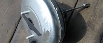
The unit in the form of a metal “barrel” is installed on the bulkhead between the engine compartment and the interior of the VAZ 2107, on the driver’s side. VUT attachment points:
- the body is screwed to the partition with 4 M8 nuts;
- the master brake cylinder is attached to the booster in front on 2 M8 studs;
- the push rod of the element goes inside the passenger compartment and is connected to the brake pedal lever.
The vacuum booster of the brake system is located on the wall of the partition between the passenger compartment and the engine compartment
The booster's job is to help the driver apply pressure to the master cylinder rod using vacuum force. The latter is created using vacuum taken from the engine through a special pipe.
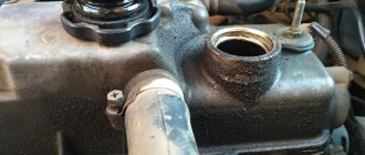
The vacuum selection hose is connected to the intake manifold from the side of the channel leading to cylinder III. The second end of the pipe is connected to the fitting of the check valve installed outside the VUT housing.
The VUT vacuum pipe (on the left in the photo) is connected to the fitting on the suction manifold
Essentially, the vacuum booster does the physical work for the driver. The latter only needs to lightly press the pedal for the car to begin to slow down.
History of appearance
The automobile industry began to gain momentum at the end of the 19th century. At the dawn of the evolution of self-running crews, little attention was paid to brakes - they were simply not needed. The friction in the transmissions was so great that the vehicles slowed down sufficiently in the absence of traction. However, the power and weight of engines grew, and already at the beginning of the 20th century, many devices designed to stop vehicles were patented.
Some innovations of that period were ahead of their time. For example, four years after the appearance of Karl Benz's car, British engineer Frederick Lanchester patented a disc brake. It took several decades for this invention to become widely accepted.
The first use of air for braking was demonstrated on its model by the Chicago manufacturer Tincher. Pressure was generated by a small pump and could be used for braking, inflating tires, or sounding a horn. The 1928 Pierce-Arrow was the pioneer of vehicles equipped with a modern vacuum brake booster.
However, despite their effectiveness, until the mid-20th century, such systems were offered by automakers only as an option. The fact is that to operate the drum brakes, the force of the foot on the pedal was sufficient. It was only with the spread of a more efficient method of braking using a disc-pad pair that servos became standard equipment. The main dates in the history of the modern vacuum pump can be considered:
- 1920s - Several inventors work on actuators for aviation using vacuum in the intake manifold.
- 1927 - Belgian engineer Albert Devandre invented a vacuum brake servo.
- 1928 - the first production car with VUT.
- Second half of the 20th century - the system becomes commonplace for production models.
Design and principle of operation of VUT
The vacuum amplifier is a metal “barrel” consisting of the following parts (the numbering in the list coincides with the positions in the diagram):
- The body is cylindrical in shape.
- Pressure rod of the main brake cylinder.
- A cover connected to the body by point rolling.
- Piston.
- Bypass valve.
- Brake pedal pusher.
- Air filter.
- Buffer insert.
- Internal plastic housing.
- Rubber membrane.
- Spring for return of the inner housing with membrane.
- Connection fitting.
- Check valve.
- Vacuum pipe.
The internal cavity of the amplifier is divided by a rubber diaphragm into 2 working chambers
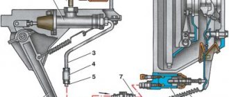
The letter “A” in the diagram indicates the chamber for supplying vacuum, the letters “B” and “C” are the internal channels, and “D” is the cavity communicating with the atmosphere. Rod pos. 2 rests against the mating part of the main brake cylinder (abbreviated as GTZ), the pusher pos. 6 is attached to the pedal.
The unit is capable of operating in 3 modes:
- The engine is running, but the driver does not press the brake. Vacuum from the manifold is supplied through channels “B” and “C” into both chambers; the valve is closed and does not allow atmospheric air inside. The spring holds the diaphragm in its original position.
- Standard braking. The pedal is partially pressed, the valve releases air (through the filter) into chamber “G”, which is why the vacuum force in cavity “A” helps to press on the GTZ rod. The plastic body will move forward and rest against the piston, and the movement of the rod will stop.
- Emergency braking. In this case, the effect of vacuum on the membrane and housing is not limited; the master cylinder rod is squeezed all the way.
Due to the pressure difference in the two chambers, the membrane helps to put pressure on the master cylinder rod
After releasing the pedal, the spring throws the body and membrane back to their original position, and the atmospheric valve closes. The check valve at the inlet of the pipe serves as protection against sudden air injection from the manifold.
Gas breakthrough into the intake manifold and further into the brake booster occurs on extremely worn engines. The reason is a loose fit of the intake valve to the cylinder head seat. During the compression stroke, the piston creates a pressure of about 7-8 atm and pushes some of the gases back into the manifold. If the check valve does not work, they will begin to penetrate into the vacuum chamber, reducing the efficiency of the VUT.
Video: how a vacuum brake booster works
How to change it yourself
Let's look at how to change the VUT using the example of the VAZ 2110, 2111, 2112. The design of the system is quite monotonous, therefore, after watching the video, you can replace the vacuum brake booster of the VAZ 2114 and many other cars.
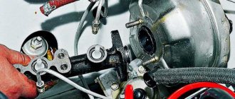
- Remove the low brake fluid level sensor connector.
- Unscrew the 2 bolts 17 securing the brake cylinder to the VUT body. There is no need to unscrew the lines, just move the cylinder with the tank a little to the side.
- Disconnect the vacuum hose from the check valve. Check the condition of the valve and install it on the new brake booster.
- Unscrew the 4 bolts securing the VUT to the engine shield. The working space in the area of the pedal assembly on the interior side is limited, so an extended socket, extension and ratchet are best suited for unscrewing.
- Disconnect the brake sensor connector.
- Pull out the VUT along with the mounting bracket and the brake pedal.
- Using pliers, remove the locking plate of the brake pedal lever rotation axis.
- Pull out the “finger” that secures the VUT pusher in the lever.
- Unscrew the 2 nuts securing the vacuum body to the bracket.
Brake booster malfunctions
Since the braking force is replaced using vacuum, most VUT malfunctions are associated with loss of tightness:
- breakdown of the rubber diaphragm due to critical wear;
- air suction along the edge of the body - at the junction between the two covers;
- the same, through the seal on the GTZ rod;
- problems with the vacuum selection hose - cracks or suction at the joints.
A typical VUT malfunction is a worn diaphragm that ruptures and allows air to pass through.
Much less common is failure of the internal bypass valve, clogging of the air filter, and shrinkage of the spring due to natural wear. In very rare cases, the spring breaks into 2 parts.
One day, an acquaintance of mine encountered an interesting effect - the “seven” slowed down tightly after starting the engine. The malfunction was preceded by constant overheating of the brake discs and drums on all wheels. It turned out that two breakdowns occurred inside the vacuum booster at once - the valve failed and the return spring broke. When trying to start the engine, the VUT was automatically triggered by the vacuum, spontaneously squeezing the main cylinder rod. Naturally, all the brake pads were seized - it was impossible to move the car.
Sometimes there is a brake fluid leak between the GTZ flange and the vacuum booster. But this problem does not apply to VUT failures, because fluid is leaking from the main cylinder. The reason is wear and loss of tightness of the sealing rings (cuffs) inside the GTZ.
Sputum around the mounting flange indicates a brake fluid leak from the turbocharger
Troubleshooting
The first sign of loss of vacuum booster seal is not deterioration of the brakes, as many sources on the Internet describe the malfunction. When air just begins to leak through the leaky membrane, the VUT continues to function properly, since the motor manages to maintain a vacuum in the front chamber. The first symptom is changes in the operation of the engine itself:
- due to air leaks into the third cylinder, the engine begins to “trouble” at idle;
- crankshaft revolutions “float”, the stronger the suction, the greater the amplitude of oscillations;
- a running engine reacts to the brake pedal and stalls when pressed sharply;
- Gasoline consumption increases.
Air leaking into the engine through the VUT causes the third cylinder to turn off - the engine begins to “triple”
If a car owner ignores the primary symptoms, the situation gets worse - the pedal becomes harder and requires more physical effort to slow down and stop the car. The car can be used further; a breakdown of the VUT does not lead to a complete failure of the brakes, but it significantly complicates driving, especially if you are not used to it. Emergency braking will become a problem.
How to make sure that the vacuum booster is leaking:
- Loosen the clamp and remove the vacuum pipe from the fitting on the manifold.
- Plug the fitting with a tight homemade plug.
- Start the engine. If the revs level out, the problem clearly lies in the amplifier.
- Remove the high voltage wire and remove the spark plug for cylinder III. If the VUT fails, the electrodes will be smoked with black soot.
If soot is observed on the spark plug of cylinder III, and the remaining spark plugs are clean, you need to check the condition of the vacuum brake booster
Whenever possible, I use the old “old-fashioned” method - I simply pinch the vacuum hose with pliers while the engine is running. If the third cylinder starts working and idle speed is restored, I proceed to checking the brake booster.
Similarly, the problem can be temporarily fixed while on the road. Disconnect the pipe, plug the fitting and calmly go to the garage or service station - the power unit will operate smoothly, without excessive fuel consumption. But remember, the brake pedal will become hard and stop responding instantly to light pressure.
Additional diagnostic methods:
- Press the brake 3-4 times and start the engine while holding the pedal. If it does not fail, the valve has probably failed.
- With the engine not running, disconnect the hose from the fitting, remove the check valve and firmly insert a pre-compressed rubber bulb into the hole. On a sealed amplifier it will retain its shape, on a faulty amplifier it will fill with air.
To check the tightness of the amplifier and the functionality of the check valve, you can use a rubber bulb
Using a bulb, you can accurately determine the location of the defect, but the vacuum booster will have to be removed. While pumping air into the chamber, wash the edges of the joints and the stem seal - bubbles will indicate the location of damage.
Video: how to check the vacuum brake booster on the “seven”
Replacement instructions
In the vast majority of cases, owners of "sevens" change the vacuum booster assembly, since repairing the unit does not always give a positive result. The main reason is difficulties in assembling, or more precisely, restoring the sealed factory rolling of the housing.
Replacement does not require special conditions or special devices; work is carried out in a garage or in an open area. Tools used:
- a set of sockets with an extension and a ratchet handle;
- socket wrench size 13 mm;
- 7 mm open-end wrench and caliper with depth gauge for adjustment;
- flat and Phillips screwdriver;
- pliers.
Along with the brake booster, it is worth changing the vacuum hose and clamps - old parts can cause air leaks.
Replacement of VUT is carried out in the following order:
- Loosen the clamp and disconnect the vacuum hose from the check valve fitting.
Assembly is performed in the same way, only in reverse order. Before installing a new VUT, be sure to adjust the length of the protruding part of the rod in order to provide the brake pedals with a slight free play. How to make the adjustment:
- Pull out the plastic buffer liner from the side of the GTZ flange, push the rod in until it stops.
- Using a depth gauge (or other measuring device), measure the length of the rod head protruding above the plane of the body. The permissible range is 1…1.5 mm.
It is also recommended to treat the rubber elements with a thick neutral lubricant before installation - this will extend the life of the unit.