Remember one important thing, before you start disassembling the stove, wiper, headlight or anything else - make sure that the fuse responsible for this circuit has not blown. And in addition to the fuse, make sure that power is supplied to the non-working unit, because the mounting block and wiring of the car Over time, subject to external factors and influences, it may fail. The wire can most often suffer mechanical damage, the connectors can oxidize, but a track in the fuse block can burn out or even some of the conductive elements simply rot into dust.
By the way, it’s not for nothing that we focus attention on the latter - the location of the fuse box in the “chisel-samar” family is not entirely successful, water often gets on it, and due to the design features and its poor protection from moisture, various troubles are practically “guaranteed” by the manufacturer.
Today we will look at the diagram and location of fuses and relays VAZ 2113, 2114, 2115
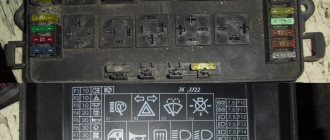
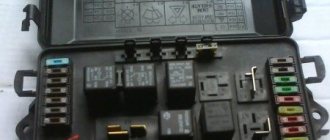
VAZ 2114 fuse mounting block diagram
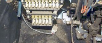
The fuse box in the VAZ-2114 is located under the hood, to the left in the direction of travel of the car, on the edge under the left wiper you will see a black box. To open it, you need to move two latches on the left. We remove the cover, there are relays and fuses.
There is a marking on the inside of the cover indicating the purpose of the relays and fuses.
Below is the purpose of all relays and fuses in the VAZ-2113 and 2114
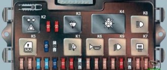
| K1 | Electric fan relay |
| K2 | Relay-breaker for direction indicators and hazard warning lights |
| K3 | Wiper relay |
| K4 | Relay for monitoring the health of brake lamps and side lights |
| K5 | Power window relay |
| K6 | Horn relay |
| K7 | Heated rear window relay |
| K8 | High beam relay |
| K9 | low beam headlight relay |
Circuits protected by fuses
| Fuse no. | Protected Circuits |
| F1(20A) | Relay for turning on rear fog lights. Rear fog lamps. Rear fog lamp activation indicator |
| F2(10A) | Turn signal lamps. Relay-breaker for direction indicators and hazard warning lights (in hazard warning mode). Hazard warning lamp |
| F3(10A) | Interior lighting. Individual interior lighting lamp. Ignition switch illumination lamp. Brake light bulbs. Trip computer |
| F4(20A) | Cigarette lighter fuse VAZ 2114.Relay for turning on the heated rear window (contacts). Rear window heating element. |
| F5(20A) | Sound signal. Relay for turning on the sound signal (coil). Horn relay (contacts), Relay switching of the electric fan (contacts). Cooling fan motor |
| F6(30A) | Power window switches. Electric windows. Power window relay (contacts) |
| F7(20A) | Heater motor. Washer motor. Rear window washer motor. Rear window wiper motor. Electric windshield wiper relay (winding). Glove compartment lamp |
| F8(7.5A) | Right fog lamp |
| F9(7.5A) | Left fog lamp. Fog light relay (contacts) |
| F10(7.5A) | Turn indicators in turn signal mode and corresponding indicator lamp. Fan motor activation relay (winding). Indicator lamp for fuel reserve, oil pressure, parking brake, brake fluid level. Battery charge indicator lamp. Instrument cluster.Voltmeter. Carburetor electro-pneumatic valve control system. Parking brake warning light relay |
| F11(7.5A) | Side lamps on the starboard side |
| F12(7.5A) | Right headlight (low beam) |
| F13(7.5A) | Left headlight (low beam) |
| F14(7.5A) | Left headlight (high beam). Indicator lamp for turning on the high beam headlights. |
| F15(7.5A) | Right headlight (high beam). |
| F16(15A) | Relay-breaker for direction indicators and hazard warning lights (in direction indicator mode). |
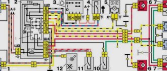
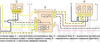
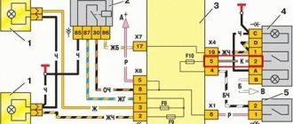
Connection diagram inside the VAZ-2114 and VAZ-2115 fuse box
(the outer number in the designation of the wire tip is the number of the block, and the inner number is the conventional number of the plug)
How to protect the cigarette lighter from damage
In order to protect both the cigarette lighter itself and its electrical circuit from malfunctions, a number of rules should be followed. We have already talked about some of them (for example, careful handling).
It is also worth mentioning the following:
- You can only install a similar fuse to replace the burnt one (it was said at the very beginning which fuse is responsible for the cigarette lighter on the VAZ 2114);
- It is absolutely not advisable to install wires in the electrical circuit of the cigarette lighter (as well as in any other system of the car) using twisting alone, since most often it is this that leads to short circuits and fires. It’s better to take the time and tin all the twists (or use special terminals);
Manual twisting of VAZ 2114 wiring
- the condition of the contacts in the mounting block should be checked periodically, and not only after any malfunction occurs;
- If you have to replace the cigarette lighter with a new one, you should take a multimeter with you to the store. With its help, you need to check the newly purchased device and make a purchase only when the new cigarette lighter is guaranteed to be in working order.
These simple tips will help you avoid mistakes and extend the life of this device.
Connection diagram of the VAZ 2114 mounting block
(the outer number in the designation of the wire tip is the number of the block, and the inner number is the conventional number of the plug): K1 – relay for turning on the headlight cleaners; K2 – relay-interrupter for direction indicators and hazard warning lights; K3 – windshield wiper relay; K4 – lamp health monitoring relay; K5 – power window relay; K6 – relay for turning on sound signals; K7 – relay for turning on the heated rear window; K8 – headlight high beam relay; K9 – relay for low beam headlights; F1-F20 – fuses
Recommendations from experts
As already mentioned, the safety element or fuse link is designed for long-term operation, but this element also fails. This most often occurs as a result of a short circuit in the conductive circuits of the vehicle itself. Another common reason for this fuse to blow is when the car owner uses the cigarette lighter as a car socket for additional electrical appliances.
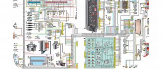
Electrical diagram of VAZ 2115 – 20 cars (left half):
1 – headlights; 2 – fog lights; 3 – air temperature sensor; 4 – electric motor of the engine cooling system fan; 5 – blocks connected to the wiring harness of the ignition system; 6 – engine compartment lamp switch; 7 – block for connection to a single-wire type audio signal; 8 – sound signal; 9 – washer fluid level sensor; 10 – front brake pad wear sensors; 11 – oil level sensor; 12 – generator; 13 – engine compartment lamp; 14 – coolant temperature indicator sensor; 15 – starter; 16 – battery; 17 – relay for turning on fog lights; 18 – coolant level sensor; 19 – brake fluid level sensor; 20 – reverse light switch; 21 – windshield wiper gearmotor; 22 – oil pressure warning lamp sensor; 23 – block for connecting to the rear window washer electric motor; 24 – windshield washer electric motor; 25 – instrument cluster; 26 – mounting block. Conventional numbering of plugs in blocks: A - block headlights; B — electric fuel pump block; C — blocks of the mounting block, ignition switch, windshield wiper gearmotor; D — interior lamp
Operating principle, design and characteristics of fuses
A protective device of this type consists of a housing, which is usually made of high-strength ceramics or special glass, and a fusible insert made of a conductive metal or alloy.
The body performs several functions:
- a fuse-link is built into it in a special way so that when the rated current of the insert is exceeded, it melts or breaks;
- the working thread is inserted into the chamber to extinguish the electric arc that occurs when the circuit breaks; this chamber is equipped in the housing;
- on the body, in those places and in the form as provided for by the fuse design, there are working contacts through which it must be connected to the general network.
Information about the characteristics of this protective device is printed on the housing. This is the rated current of the fuse link and the rated current of the fuse body at which it breaks.
According to their performance characteristics, these protective elements are divided into:
- fast-acting;
- low voltage;
- designed for medium voltage;
- manufactured for high voltages.
In automotive networks, the first two types are used.
The defining point showing the purpose of a particular protective device with a fuse link is its current characteristics. It is she who speaks about the range in which this element is ready to work.
- To protect electric motors, fuses are installed whose inserts can withstand the rated current and its excess for a sufficiently long time necessary to start the main mechanism and reach its operating range. As a rule, such chargers (protective devices) are marked - g - as devices ready for protection from both overload and short circuit.
- There are protective devices that operate effectively during short circuits and protect all equipment from very high voltage currents. Such chargers are marked - a - for protection only against short circuits.
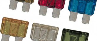
Fuses for cars have several versions:
- low-current inserts, in networks up to 20 A, made of glass with a thin wire insert, there are ceramic cases, the ends are made of metal;
- fork inserts, most commonly used in vehicles, come in miniature and regular types.
According to GOST, a painting system for fusible chargers has been adopted depending on the rated current of the insert. 2 A - gray, 4 A - pink, 5 A - orange-yellow, 7.5 A - brown, 10 A - red, 15 A - blue, 20 A - yellow, 25 A - white, 30 A - green.
Fuse box in the engine compartment
It is mounted on the battery shelf on the positive terminal side of the battery.
It contains fuses rated for currents greater than 30 A. Fuse diagrams for LADA Granta of different years of manufacture and their explanation are given below.
For cars assembled in 2011-2014
| Designation | Denomination, A | Protected circuit |
| F1 | 30 | Main relay, interior unit (fuse circuits F1 and F21 |
| F2 | 60 | Generator |
| F3 | 60 | Generator |
| F4 | 30 | Cooling fan |
| F5 | 50 | EUR |
| F6 | – | Reserve |
For cars assembled in 2015
| Designation | Denomination, A | Protected circuit |
| FF1 | 50 | Heated windshield |
| FF2 | 60 | Generator |
| FF3 | 60 | Generator |
| FF4 | 30 | Electric radiator cooling fan (equipped without air conditioning) |
| 40 | Electric radiator cooling fan (equipped with air conditioning system) | |
| FF5 | 50 | Electromechanical power steering |
| FF6 | 40 | ABS ECU |
For cars assembled in 2016, 2022
| Designation | Denomination, A | Protected circuit |
| FF1 | 50 | Heated windshield |
| FF2 | 60 | Generator |
| FF3 | 60 | Generator |
| FF4 | 30 | Electric radiator cooling fan (equipped without air conditioning) |
| 40 | Electric radiator cooling fan (equipped with air conditioning system) | |
| FF5 | 50 | Electromechanical power steering |
| FF6 | 40 | ABS ECU |
For cars assembled from 2022
| Designation | Denomination, A | Protected circuit |
| FF1 | 60 | Generator |
| FF2 | 60 | Generator |
| FF3 | 30 | Electric radiator cooling fan (equipped without air conditioning) |
| 40 | Electric radiator cooling fan (equipped with climate control or air conditioning) | |
| FF4 | 40 | ABS/ESP controller |
| FF5 | 25 | ABS/ESP controller |
| FF6 | 50 | Electric power steering controller |
Recommendations for care and maintenance
- Buy original fuses. Domestic or foreign, it doesn’t matter;
- Install strictly in accordance with amperage ratings. Unacceptable with lower or higher current strength. In the first case, this will lead to damage to the module, in the second - to breakdown of the unit, which is attached to the fuse;
- Carefully check the quality of fixation of terminals and limit switches on the board. If loose, tighten and press with pliers. A spark can cause a fire and melting occurs;
- If moisture gets in or condensation forms inside the mounting block, remove the cover, dry it, and if necessary, blow it with a stream of compressed air.
Carry out preventive and diagnostic work in the fuse box with the battery terminals removed in order to prevent a short circuit in the circuit.
The average service life of fuses is 40 – 60 thousand km. The service life of foreign analogues is 10–15% longer. Before replacing, read the instructions and get advice from service station specialists.
Sources
- zapchasti.expert/predoxraniteli/predoxraniteli-vaz-2115.html
- vaznetaz.ru/predoxraniteli-i-rele-vaz-2114-2115-2113
- drive2.ru/l/5419303/
Additional block
It is located at the bottom right of the center console, behind the protective cover.
Photo - diagram
Decoding the scheme
p, blockquote 22,0,0,0,0 —>
- Main relay (engine control unit)
- Cooling fan
- Fuel pump
- F1 - 15A Main relay (engine control unit, ignition module)
- F2 - 15A Constant power supply to the controller, relay for turning on the electric fan (winding), canister purge valve, air flow sensor, speed sensor, oxygen sensor (heating)
- F3 - 15A Fuel pump, fuel pump relay (contacts), injectors
Individual fuses and relays may be located outside the main units.
That's all. And if you have anything to add to the material, then write in the comments.
Source
Other causes of malfunction
Typically, a cigarette lighter failure is caused by a blown fuse. You can easily identify and fix this breakdown with your own hands. But sometimes it breaks for other reasons. Therefore, if checking and replacing the fuse element does not help, you should pay attention to the following:
- Oxidation of contacts and loose contact connections. It is necessary to inspect the contacts and connections. If necessary, they should be cleaned of oxides and contaminants. To do this, it is recommended to use WD-40 liquid or kerosene and a soft, clean cloth. You also need to tighten all connections.
- Light bulb condition. You can check its functionality in the following way:
- Open the car hood;
- Remove the terminals from the battery;
- Remove the fasteners that hold the cigarette lighter housing;
- Remove the plastic casing;
- Pull out the light bulb;
- Inspect the lamp. Its malfunction is usually clearly visible during visual inspection;
- If the light bulb burns out, replace it with a new one that is known to be good;
- Connect the battery.
- Cigarette lighter functionality. A short circuit or breakage of individual parts could occur in it. Often a malfunction can be noticed by eye. If the problem is not noticeable, you should test the device using a multimeter. According to the readings of the device, it will become clear that the element is broken.
This part is usually beyond repair. Therefore, it will need to be replaced. This spare part is inexpensive and is sold in almost all automobile stores. As a rule, it is always available. Therefore, you don’t need to order and wait for it.
These are the main reasons for the failure of this device. You can easily diagnose and eliminate them on your own. Malfunctions of this part usually do not require a visit to a service station. This may be necessary as a last resort, when all self-diagnosis methods have not led to a solution to the problem. The rules do not prohibit the operation of a machine with this breakdown. It does not harm the car at all and may cause virtually no discomfort. But despite this, it is advisable to repair the device within a reasonable time. After all, even if you and your passengers do not smoke or are accustomed to using a lighter, you may unexpectedly need to charge a dead mobile phone. It may be unexpectedly needed in the event of an accident or other emergency. And, if this problem is accompanied by problems with other, more important equipment, there is no point in delaying repairs.
Main unit
The main fuse and relay box is located in the rear part of the engine compartment, in the installation department, under a protective cover.
The current diagram for your vehicle can be printed on the back of the protective cover. Check your appointment!
Option 1
Scheme: 2114/ 2115 — 3722010, -3722020, -3722010-30, -3722010-38, -3722010-40, -3722010-48, -3722010-60, -3722010-68
Description of fuses
p, blockquote 10,0,0,0,0 —>
| F1 | 10A Rear fog lights, rear fog light indicator lamp |
| F2 | 10A Turn signals and turn signal breaker relay. Alarm system. Hazard warning lamp |
| F3 | 7.5A Interior and luggage compartment lighting systems (interior lamp, luggage compartment lamp, ignition key illumination). Stop lamp - brake signal, on-board computer backlight lamp. Engine control lamp |
| F4 | 20A Control of heated rear window. Portable lamp connection socket |
| F5 | 20A Relay for control and activation of the sound signal. Cooling system engine switch fuse and relay |
| F6 | 30A Control and relay for switching on electric glass lifts |
| F7 | 30A Electric motor control - heating system, interior heater, windshield washers, headlight cleaners. cigarette lighter , glove box lamp. Turn on the heated rear window. |
| F8 | 7.5A Turning on the right fog lamp |
| F9 | 7.5A Turning on the left fog lamp |
| F10 | 7.5A Side light of the left side body, indicator light for turning on the side lights (on the display), lamps for illuminating the license plate and engine compartment, illumination lamp for switches, cigarette lighter, heater control levers. Instrument lighting switch. |
| F11 | 7.5A Right side body marker light |
| F12 | 7.5A Front right low beam headlight |
| F13 | 7.5A Front left low beam headlight |
| F14 | 7.5A Front left high beam headlight. Light indicator lamp. |
| F15 | 7.5A Front right high beam lamp. |
| F16 | 15A Body turn signals, relay - turn signal and hazard warning light breaker. Control relay and reverse lamps, indicator lamps for the on-board instrument control system, lamps for oil pressure, handbrake activation, brake fluid level, battery charge. On-board computer, engine generator winding. |
| F17 - F20 | Spares |
Fuse number 7 at 30A is responsible for the operation of the cigarette lighter.
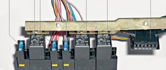
Relay purpose
p, blockquote 12,1,0,0,0 —>
- K1 - Relay for turning on headlight cleaners
- K2 - Relay interrupter for direction indicators and hazard warning lights
- K3 - Windshield wiper relay
- K4 - Relay for monitoring the health of stop lamps and side lights
- K5 - Window lift relay
- K6 - Horn relay
- K7 - Rear window heating relay
- K8 - High beam relay
- K9 - Relay for low beam headlights
How to get to the right fuse
VAZ 2114 fuse box
Almost the entire electrical circuit of the VAZ 2114 is protected by knife-type fusible elements. The most powerful consumers such as headlights, electric fuel pump, etc. are already mounted via a relay. Most fuses can be found in the so-called. fuse box VAZ 2114. However, this diagram has exceptions:
- Next to the battery in the engine compartment there is a fog light relay;
- The fuses for the injection system are mounted under the instrument panel.
No special tools are required to dismantle VAZ 2114 fuses. Therefore, first of all, look at the VAZ 2114 fuse box, which is located under the hood of the car opposite the driver next to the left pillar. In order to open the fuse box, protected by a plastic cover, you need to lightly push a couple of cover latches towards you, lift it and remove it. After this, you will immediately be able to see the modules responsible for the electrical safety of various vehicle systems.