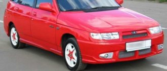
This contact assignment is suitable for Electronic Control Units BOSCH M7.9.7 / January 7.2, used on LADA (VAZ) 2111, 2114, 2109 and others, on which engines 21114 and 21124 were installed.
| № | 8 valve engine (21114) | 16 valve engine (21124) | Car with two oxygen sensors (Euro 3) |
| 1 | Second cylinder ignition coil control output | ||
| 2 | Ignition coil control output for cylinders 2-3 | Third cylinder ignition coil control output | |
| 3 | Ignition coil weight | ||
| 4 | Fourth cylinder ignition coil control output | ||
| 5 | Ignition coil control output for cylinders 1-4 | Ignition coil control output of the first cylinder | |
| 6 | Injector pulse of the second cylinder | ||
| 7 | Injector pulse of the third cylinder | ||
| 8 | Tachometer output | ||
| 9 | Not used | ||
| 10 | Fuel consumption signal | ||
| 11 | Not used | ||
| 12 | Terminal 30. Constant power supply from battery | ||
| 13 | Terminal 15. Power from the ignition switch | ||
| 14 | Main relay control output | ||
| 15 | Crankshaft sensor input (A) | ||
| 16 | Throttle position sensor signal input (C) | ||
| 17 | Throttle sensor ground (B) | Weight TPS, Rough Road Sensor | |
| 18 | Oxygen sensor 1 signal input (A) | ||
| 19 | Knock sensor input | ||
| 20 | Knock sensor weight | ||
| 21 | Not used | ||
| 22 | Not used | ||
| 23 | Not used | ||
| 24 | Not used | ||
| 25 | Only on Bosch - high current output, reserve | ||
| 26 | Only on Bosch - high current output, reserve | ||
| 27 | Injector pulse of the first cylinder | ||
| 28 | Not used | Second oxygen sensor heater control output | |
| 29 | Not used | Engine cooling fan control output | |
| 30 | Not used | ||
| 31 | Check lamp | ||
| 32 | Power supply (+5V) throttle position sensor | Power supply for TPS and rough road sensor | |
| 33 | Power supply (+5V) of the Mass Air Flow Sensor | ||
| 34 | DPKV input, contact “B” | ||
| 35 | Coolant Temperature Sensor Ground | Weight of Coolant Temperature Sensor, Mass Air Flow Sensor and two Oxygen Sensors | |
| 36 | Mass Air Flow Sensor Weight | ||
| 37 | Signal input from Mass Air Flow Sensor | ||
| 38 | Not used | ||
| 39 | Signal input from Coolant Temperature Sensor | ||
| 40 | Signal input from intake air temperature sensor | ||
| 41 | Not used | ||
| 42 | Not used | Signal input from Rough Road Sensor | |
| 43 | Not used | ||
| 44 | +12V power input after main relay | ||
| 45 | Phase sensor power output (Camshaft sensor) | ||
| 46 | Canister purge valve control output | ||
| 47 | Fourth cylinder injector pulse | ||
| 48 | Oxygen sensor heater control output | ||
| 49 | Not used | ||
| 50 | Controlling the additional starter relay | ||
| 51 | ECU weight | ||
| 52 | Not used | ||
| 53 | ECU weight | ||
| 54 | Not used | ||
| 55 | Not used | Second oxygen sensor signal input | |
| 56 | Not used | ||
| 57 | Input for encoding calibration data options. The controller memory can store two options for calibration data, one of which is selected by connecting or not connecting this contact to ground in the wiring harness. In the absence of a connection to ground, this contact is supplied with on-board voltage through the internal resistor of the controller. | ||
| 58 | Not used | ||
| 59 | Speed Sensor Signal | ||
| 60 | Not used | ||
| 61 | Mass of Output Cascades | ||
| 62 | Not used | ||
| 63 | +12V power input after main relay | ||
| 64 | Contact "D" of the Idle Air Controller | ||
| 65 | Idle Air Control Terminal "C" | ||
| 66 | Idle Air Control Terminal "B" | ||
| 67 | Idle Air Control Terminal "A" | ||
| 68 | Output to control the engine cooling fan relay | ||
| 69 | Air conditioner relay control output | ||
| 70 | Output for controlling the fuel pump relay | ||
| 71 | K‑Line (Diagnostic line) | ||
| 72 | Not used | ||
| 73 | Not used | ||
| 74 | Not used | ||
| 75 | Air conditioner request signal | ||
| 76 | Request to turn on power steering | ||
| 77 | Not used | ||
| 78 | Not used | ||
| 79 | Phase sensor signal input | ||
| 80 | Weight of output stages | ||
| 81 | Not used | ||
PRINCIPLE OF OPERATION AND LOCATION OF THE DEVICE
The electronic engine control unit starts working when the ignition is activated; it continuously functions while driving, collecting information from various fourteenth sensors.
The received information is analyzed by the processor and, based on the results of the analysis of the received data, the device controls the functional systems of the VAZ-2114. The VAZ 2114 engine control unit receives information from the following fourteenth sensors:
- (sensor) speed of movement;
- Oxygen;
- Detonation;
- Fuel injection phases;
- Crankshaft position;
- Throttle position;
- Instant air flow;
- Liquid temperatures in the cooling system.
Based on the information received, the ECU on the VAZ 2114 controls the following systems and components of the vehicle:
- Adsorber;
- Ignition system;
- Injectors and fuel pump;
- Ventilation;
- Automatic diagnostic programs;
- Idle speed control unit.
The brains on the VAZ 2114 consist of 3 separate devices, each of which has an individual type of memory:
- Random access storage device - a RAM block is a system with short-term memory. RAM contains information about recent errors that the ECU detected in the fourteenth systems and various current vehicle parameters. The RAM memory is completely updated when the ignition is turned off.
- A programmable permanent storage device is the main memory unit; it stores the ECU firmware. The PROM contains information about the results of calibrations of the fourteenth systems, as well as the power unit control algorithm. The EPROM memory is permanent; it is stored when the ignition is turned off. With certain skills, the EPROM block can be reprogrammed, which will improve the power and dynamics of the VAZ 2114.
- An electrically reprogrammable storage device is the main functional purpose of the unit - protecting the machine. The EEPROM contains data from the fourteenth anti-theft system - passwords and their encoding. It will be possible to start the engine only after the EPROM and the immobilizer compare data with each other.
Article on the topic: Changing the front and rear brake pads of a VAZ 2110 yourself
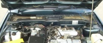
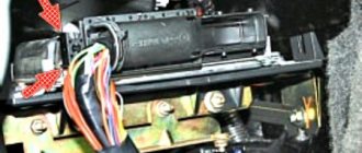
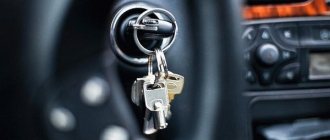
The VAZ 2114 ECU is hidden inside the dashboard, right under the dashboard. In order to get to the brains, you need to use a Phillips screwdriver to unscrew the fixing screws and remove the side panel of the dashboard from the passenger seat. There you will see a longitudinal plastic brain housing, which is inserted inside a stainless steel retainer.
To remove the control unit, you need to unscrew the fixing bolt and pull the lock towards you, after which the device can be freely removed (you must first completely de-energize the car by removing all terminals from the battery).
You remove the panel, and behind it the “brains” - everything is simple!
Let's compare architectures
At the moment, there are many different ADC architectures in the world. Each of them has its own advantages and disadvantages. There is no architecture that would achieve the maximum values of all the parameters described above. Let's analyze what maximum speed and resolution parameters the companies producing ADCs were able to achieve. We will also evaluate the advantages and disadvantages of each architecture (you can read more about the various architectures in the article on Habr). Architecture comparison table
| Architecture type | Advantages | Flaws | Maximum resolution | Maximum sampling rate |
| flash | Fast converter. The conversion is carried out in one clock cycle. | High power consumption. Limited resolution. Requires a large crystal area (comparators). It is difficult to coordinate a large number of elements (as a result, low yield). | 14 bit 128 kSa/s AD679 | 3 bit 26 GS/s HMCAD5831 |
| folding-interpolated | Fast converter. The conversion is carried out in one clock cycle. Requires fewer comparators due to preliminary “convolution” of the entire processing range into a narrower range. Occupies less space. | Errors associated with the nonlinearity of the convolution block. Delay for establishing levels in the convolution block, which reduces the maximum fs. Medium resolution. | 12 bit 6.4 GS/s ADC12DL3200 | 12 bit 6.4 GS/s ADC12DL3200 |
| SAR | High accuracy. Low power consumption. Easy to use. | Limited speed. | 32 bit 1 MSa/s LTC2500 | 10 bit 40 MSa/s XRD64L43 |
| pipeline | Fast converter. Highest accuracy among fast ADCs. Doesn't take up a large area. Has lower consumption among similar fast converters. | Pipeline delay. | 24 bit 192 kSa/s AK5386 | 12 bit 10.25 GS/s AD9213 |
| dual-slope | Average conversion accuracy. Simplicity of design. Low consumption. Resistance to changes in environmental factors. | Processes low frequency Signals (low fs). Mediocre resolution. | 12+sign bit 10 S/s TC7109 | 5+sign bits 200 kSa/s HI3-7159 |
| ∑-Δ | The highest conversion accuracy thanks to the “Noise shaping” effect (specific filtering of quantization noise) and oversampling. | Cannot work with wideband signal. | 32 bits 769 kSa/s AK5554 | 12 bit 200MS/s ADRV9009 |
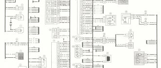
ECU pinout diagram January 7.2 VAZ 2114
Where is the control unit for the Priora central locking located
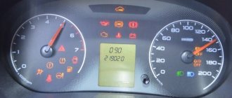
? The VAZ 2114 controller breaks down very often. The system has a self-diagnosis function - the ECU queries all components and issues a conclusion about their suitability for operation. If any element fails, the “Check Engine” lamp will light up on the dashboard.
ECU pinout diagram January 7.2
It is possible to find out which sensor or actuator has failed only with the help of special diagnostic equipment. Even with the help of the famous OBD-Scan ELM-327, loved by many for its ease of use, you can read all engine operating parameters, find the error, eliminate it and delete it from the memory of the VAZ 2114 ECU.
Article: 346027
Order code: 095401
- Buy with this product
- show more
Buy analogues
- There are no reviews for this product yet.
Schematic electrical diagrams, connecting devices and pinouts of connectors
The fuel pump on a car is designed to supply fuel to the combustion chamber. Its operation is controlled using a relay. On a VAZ (depending on the model), the fuel supply unit can be electrical or mechanical - it all depends on the fuel supply system. On a fuel-injected car, the fuel pump is located in the tank. When the ignition is turned on, voltage is supplied to the terminals of the unit and it begins to pump fuel. If the required pressure is created in the system, the relay automatically turns off the fuel pump - the engine is ready to start.
When the ignition is turned on, the relay creates pressure in the fuel lines by turning on the fuel pump (BN) for a couple of seconds. After this, the BN will work either when the engine is cranked by the starter, or when the engine is running.
Sometimes this system needs repairs - there is nothing complicated here, and the editors of the 2Skhema.ru website will tell you how to do it yourself. Let's start with the BN pinout, then we will indicate it on the diagrams and at the end there will be instructions for replacing the fuel supply elements.
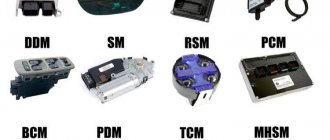
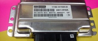
Modifications of electronic control units for VAZ cars
Electronic engine control system in a car: we understand what it is and the principle of operation
The modification on the seventh of January depends on the engine size. Control units produced by BOSCH were installed only on those cars that were exported (they met the EURO-3 eco-standard). For 1.5 l 8 cl. the motors were equipped with the following ECUs:
| 21114-1411020-80 | BOSCH-7.9.7, E-2.1.5 liters, 1st serial version. |
| 21114-1411020-80h | BOSCH-7.9.7, E-2.1.5 liters, tuning |
| 21114-1411020-80 | BOSCH-7.9.7+, E-2.1.5 liters, |
| 21114-1411020-80 | BOSCH-7.9.7+, E-2.1.5 liters, |
| 21114-1411020-30 | BOSCH-7.9.7, E-3.1.5 liters, 1st serial version. |
| 21114-1411020-81 | JANUARY_7.2, E-2.1.5 liters, 1st_serial version, unsuccessful, replacement_A203EL36 |
| 21114-1411020-81 | JANUARY_7.2, E-2.1.5 liters, 2nd_serial_version.unsuccessful, replacement_A203EL36 |
| 21114-1411020-81 | JANUARY_7.2, E-2.1.5 liters, 3rd_serial_version |
| 21114-1411020-82 | ITELMA, with acid sensor, E-2,1,5 liter, 1st_version |
| 21114-1411020-82 | ITELMA, with acid sensor, E-2,1,5 liter, 2nd_version |
| 21114-1411020-82 | ITELMA, with acid sensor, E-2,1,5 liter, 3rd_version |
| 21114-1411020-80h | BOSCH_797, without acid sensor, E-2, din., 1.5 liters |
| 21114-1411020-81h | JANUARY_7.2, without acid sensor, CO, 1.5 liter |
| 21114-1411020-82h | ITELMA, without acid sensor, CO, 1.5 liter |
For 1.6 liter engines:
| 21114-1411020-30 | BOSCH_797,E-2,1.6L,1st_series (software glitches) |
| 21114-1411020-30 | BOSCH_797,E-2,1.6L,2nd_series |
| 21114-1411020-30 | BOSCH_797+,E-2,1.6L,1st_series |
| 21114-1411020-30 | BOSCH_797+,E-2,1.6L,2nd_series |
| 21114-1411020-20 | BOSCH_797+,E-3,1.6L,1st_series |
| 21114-1411020-10 | BOSCH_797,E-3,1.6L,1st_series |
| 21114-1411020-40 | BOSCH_797,E-2,1.6L |
| 21114-1411020-31 | JANUARY_7.2, E-2, 1.6L, 1st_series (unsuccessful) |
| 21114-1411020-31 | JANUARY_7.2, E-2, 1.6L, 2nd_series |
| 21114-1411020-31 | JANUARY_7.2, E-2, 1.6L, 3rd_series |
| 21114-1411020-31 | JANUARY_7.2+, E-2, 1.6L, 1st_series, new_hardware.version. |
| 21114-1411020-32 | ITELMA_7.2,E-2,1.6L,1st_series |
| 21114-1411020-32 | ITELMA_7.2,E-2,1.6L,2nd_series |
| 21114-1411020-32 | ITELMA_7.2,E-2,1.6L,3rd_series |
| 21114-1411020-32 | ITELMA_7.2+, E-2, 1.6L, 1st_series, new_hardware.version. |
| 21114-1411020-30CH | BOSCH_with acid sensor, E-2, din, 1.6L |
| 21114-1411020-31CH | JANUARY_7.2, without acid sensor, CO, 1.6 liter. |
Generator design
Fuses and control unit daewoo lanos
The second power source of any car is the generator. It is necessary to power all consumers when the engine is running. The generator consists of the following parts:
- Rotary excitation winding.
- Slip rings on the rotor.
- Bearings.
- Front and back covers.
- Stator winding.
- Voltage regulator.
- Pulley with impeller.
- Diode block.
- Capacitor.
The design is proven and is also used in all modern cars. The generator occupies a central place in the wiring of the VAZ-2114. Its connection diagram is quite simple (see above) - the wire goes from the power contact to the positive of the battery. Thanks to the generator, the optimal level of battery charge and power supply to all consumers is maintained.
Electrical equipment of the front of the car
The following is a breakdown of the front cable bundle, excluding fog lights:
- 1 – output terminals of the starter contact group;
- 2 – battery, connection of power cables;
- 3 – standard “father” of the generator;
- 4 – blocks for connecting the power conductors of the battery and generator to the front assembly of electrical equipment;
- 5 – part of the fuse mounting block;
- 6 – standard horn;
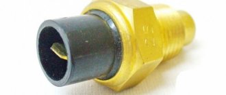
- 7 – sensor that measures the temperature of antifreeze in the power plant;
- 8 – standard sensor for measuring the washer fluid residue in the tank; when activated, the corresponding indicator on the device lights up;
- 9/10 – left and right headlights, respectively;
- 11 – external thermometer;
- 12 – standard reverse gear lamp switch;
- 13 – drive of the electric fan of the generator;
- 14 – connector to the ignition system module;
- 15 – in the VAZ 2114 scheme the injector is not used, it is used only for the carburetor;
- 16 – electronic brake fluid level sensor; in case of a critical drop, an exclamation mark lights up on the instrument panel;
- 17 – built-in oil level sensor in the crankcase compartment of the power plant; when activated, the red light on the instrument panel lights up;
- 18 – similar for the engine cooling system;
- Ш5-8 – mounting block connectors;
- A1/2, B1/2 – grounding terminals.
Where is the ECU located on the VAZ 2114
In a VAZ 2114 car, the control module is installed under the center console of the car, in particular, in the middle, behind the panel with the radio. To get to the controller, you need to unscrew the latches on the side frame of the console. As for the connection, in Samar modifications with a one and a half liter engine, the mass of the ECU is taken from the power unit housing, from the fastening of the plugs located to the right of the cylinder head.
Location of the VAZ 2114 ECU
In cars equipped with 1.6- and 1.5-liter engines with a new type of ECU, the mass is taken from the welded stud. The pin itself is fixed on the metal body of the control panel near the floor tunnel, not far from the ashtray. During production, VAZ engineers, as a rule, do not securely fix this pin, so over time it can become loose, which will lead to the inoperability of some devices.
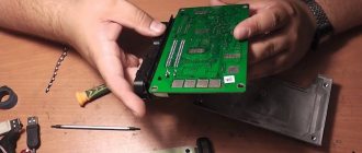
Instructions for removing and replacing the computer
The need to dismantle the ECM unit 16 of the ten valve engine arises if repairs are necessary when faults are identified. The repair process itself will depend on what exactly happened in the operation of the ECU. For example, if the contacts on the module connector have oxidized, the unit must be dismantled to clean or replace them. If the reason lies in damage to the housing, then the device must be removed for replacement; if water has gotten inside, then the module should be removed in order to dry it. Only after you have dried the block can it be tested.
Description of "brains"
The VAZ 2114 ECU is an on-board computer of the vehicle, designed to control the main systems of the car. The parameters of the control module affect both the functionality of certain regulators and the operation of the engine as a whole.
That is, the importance of this system cannot be denied
Controller Location
In VAZ 2114 and VAZ 2115 cars, the control module is installed under the center console of the car, in particular, in the middle, behind the panel with the radio. To get to the controller, you need to unscrew the latches on the side frame of the console. As for the connection, in Samar modifications with a one and a half liter engine, the mass of the ECU is taken from the power unit housing, from the fastening of the plugs located to the right of the cylinder head.
Location of the ECU in the Chetyrka
In cars equipped with 1.6- and 1.5-liter engines with a new type of ECU, the mass is taken from the welded stud. The pin itself is fixed on the metal body of the control panel near the floor tunnel, not far from the ashtray. During production, VAZ engineers, as a rule, do not securely fix this pin, so over time it can become loose, which will lead to the inoperability of some devices.
Design and principle of operation
The control unit of the electronic system operates in accordance with the indicators received from the sensors:
- speed;
- detonation;
- lambda probe;
- fuel injection phases;
- crankshaft position;
- throttle position;
- air flow meter;
- antifreeze temperature.
In accordance with the data received from these controllers, the control module controls the following systems:
- ignition;
- adsorber;
- injectors, as well as a fuel pump;
- ventilation and heating system;
- programs for diagnosing vehicle performance;
- idle speed regulator (video author - Evgeniy Vekhter).
As for the device, the control module structurally consists of the following components:
- RAM or random access memory. This module contains basic data about recently identified errors detected by the electronic system in the operation of various components. When the driver turns off the ignition, the RAM unit is updated, causing this data to disappear.
- PROM is the main element of the system; it contains the firmware of the control module. It should be noted that this memory block contains all the necessary data on the calibration of the “four” systems along with the general engine control algorithm. Unlike RAM, EPROM is a permanent memory, so the data stored in it is retained even after the ignition is turned off. If necessary, this module can be reconfigured, that is, reprogrammed, which can lead to improved power as well as vehicle dynamics.
- ERPZU - the primary function of this module is to protect the car. The EEPROM memory contains information from the anti-theft installation - passwords, as well as encoding of the main parameters. Starting the engine will only be possible if the EEPROM successfully checks with the data contained in the immobilizer memory.
Typical malfunctions: their symptoms and causes
What are the signs that indicate a faulty ECU:
- there are no control signals coming from actuators (IAC, flow meter, various sensors, etc.);
- there is no signal for interaction with the ignition system, fuel pump, injectors and other elements;
- when connecting a diagnostic tester, there will also be no connection with the electronic system;
- Burnt contacts and mechanical damage to the device may also be a sign.
What reasons contribute to the failure of the control device:
- electrical circuit shorted or broken;
- improper electrical repairs, during which errors were made, in particular, we are talking about installing or repairing an anti-theft system;
- lighting a dead battery from a car with the engine running;
- a breakdown of the unit can be caused by incorrect connection of the battery terminals - plus instead of minus and vice versa;
- disconnecting the battery contacts when the engine is running;
- moisture on the electronic system module board;
- mechanical damage to the device as a result of an accident (the author of the video about repairing the control module in a garage is the Auto Practice channel).
Malfunctions of the central unit of body electronics TsBKE
The TsBKE 21900-3840080-10/20 block is designed to perform many functions.
This includes control of external and internal lighting lamps, door locks, windshield wipers, alarm systems, heated seats, electric mirror drives, etc. Installed on Priora, Kalina, Granta cars.
The turns on the Priora do not work, the right turn signals on the Kalina, Priora, and Grant are constantly on. Owners constantly call us on the phone with questions like this. The body electronics unit of modern AvtoVAZ cars does not stand the test of time.
The main signs of a faulty ECU of VAZ cars:
- Turn signals do not work;
- one side of the turn signals is constantly on;
- The trunk opening function does not work;
- no control of one or more functions;
- All functions of the unit do not work, diagnostics are not possible.
“Comfort block”
VAZ cars often fail. Problems with this unit are common, and replacing the unit is not always cheap. A new block costs 6-7 tr. plus 1.5 rub. block replacement. Of course, you can find a used version, but it will take a lot of time.
We offer prompt repairs
“comfort block”.
January 5.1.x
Already in 2003, the fourteenth began to be equipped with improved brains (which, by the way, were suitable for both the thirteenth and fifteenth) - this is “January 5.1x”. this controller was produced in three variations regarding fuel injection: simultaneous injection, pair-parallel injection and phased injection.
By the way, this type of brain matches the parameters well with “VS (Itelma) 5.1” or “BOSCH M1.5.4”, which allows you to interchange domestic firmware with foreign ones. Below are models of all three lines of brains.
The VAZ 2114 control unit, represented by different models of the same line, will be built on a single base, and the models will differ only in the switching of injectors or heating of the DC.
For "January":
January 5.1.x
Siemens Deka injectors
There is no certainty with Siemens injectors, since the plant can install injectors of different markings on the same engine. However, there is a clear difference between the injectors for eight-valve and 16-valve engines.
They are marked as VAZ20734 (orange markings) and 20735 (blue markings). On eight-valve engines, a Siemens 6393 nozzle with a thick torch can be used. Its productivity is 1.662 mg/sec, and its operating pressure is 3 atm. Each of these injectors can be installed on a VAZ-2114 engine.
Injector Siemens-vaz20734 Injector Siemens-vaz20735
Serial firmware VAZ Bosch M7.9.7+
Bosch M7.9.7 new hardware implementation (M7.9.7+) Software ID VAZ number Note B103EQ12 2111 – 1411020-80 1 Serial version for new hardware implementation, E2 standards B103ER12 2111 – 1411020-80 2 Serial version for new hardware implementation, E2 standards B104DQ17 21114 – 1411020-30 1 Serial version for new hardware implementation, E2 standards B104DR17 21114 – 1411020-30 2 Serial version for new hardware implementation, E2 standards B105DQ09 21124 – 1411020-30 1 Serial version for new hardware implementation, E2 B1 standards 05DR09 21124 – 1411020-30 2 Serial version for new hardware implementation, standard E2 B105DR10 21124 – 1411020-30 3 Serial version for new hardware implementation
ECU made in France, E2 standards B108DQ09 21124 – 1411020-10 1 Serial version for new hardware implementation, E3 standards B108DR09 21124 – 1411020-10 2 Serial version for new hardware implementation, E3 standards B109DR02 21124 – 1411020-20 3 Serial version for new device noah implementations, E3 standards B119DQ01 21114 – 1411020-20 1 Euro‑3 serial version for new hardware implementation, XC05_M7A1, E3 standards B119DR02 21114 – 1411020-20 Bogdan, serial version, software XC06_M7A1, E4 standards B120EQ16 21214 – 1411020-30 1 Serial version for new hardware implementation, E2 standards B120ER16 21214 – 1411020-30 2 Serial version for new hardware implementation, E2 standards B120ER19 21214 – 1411020-30 3 Serial version for new hardware implementation, E2 standards B122HR01 21230 – 1411020-90 1 Serial version for new hardware implementation on Niva - Chevrolet vehicles, E2 standards Attention! The firmware has a problem with turning on the fans B122HR91 21230 – 1411020-90 2 Serial version for the new hardware implementation on Niva – Chevrolet, E2 standards 22XC052S 21230 – 1411020 “Clone” B122HR01, E4 standards 22YC041S 21230 – 1411020- 40 Niva – Chevrolet, E4 standards B114ER18 21214 – 1411020-20 Serial version for the new hardware implementation on the Niva 21214 car, E3 standards B114ER17 21214 – 1411020-20 Serial version for the new hardware implementation on the Niva 21214 car. Version from the export car, E3 standards B126ES01 2104 – 1411020-10 1 Serial version for the new hardware implementation for 1.45 l classic cars, E2 standards B126ER02 2104 – 1411020-10 2 Serial version for the new hardware implementation for 1.45 l classic cars, norms E2 B102CQ05 Kalina 1 Serial for Kalina, standards E3 B102CR06 Kalina 2 Serial for Kalina, standards E3 B101CR01 11183 – 1411020-02 1 Serial for Kalina, standards E2 B101CR02 11183 – 1411020-02 2 Serial for Kalina, standards E2 B104CR 01 21114 – 1411020- 40 Viburnum, paper nameplate, E3 standards B104CR02 21114 – 1411020-40 Viburnum, differences from CR01 only in fan temperature thresholds, E3 standards B103CU03 21114 – 1411020-40 Viburnum, paper nameplate, without DND, E3 standards B173DR01 21126 – 141102 0-10 1 Serial for Priora, standards E3 B174DR03 21126 – 1411020-00 2 Serial for Priora, standards E4* B174DR04 21126 – 1411020-00 3 Serial for Priora, equipped with power steering, standards E4* B174DT05 21126 – 1411020-30 4 Serial for Pria yell, norms E4* B174DT06 21126 – 1411020-30 5 Serial for Priora, standards E4* B174DT07 21126 – 1411020-00 6 Serial for Priora, standards E4* B173СR03 11194 – 1411020 1 Serial for Kalina 1.4 l., standards E3 B174 CR03 11194 – 1411020 -10 2 Serial version for Kalina 1.4 l., E3 standards B174СT04 11194 – 1411020-10 3 Serial version for Kalina 1.4 l., E3 standards 22YB072S 2123 – 1411020-30 1 Serial version Euro‑3 for new hardware implementation on a /m Niva - Chevrolet, E3 standards OPP firmware** Bosch M7.9.7+ B120ER1733XCO305B133ER17 21214 – 1411020-30 OPP firmware from Niva 1.8 (in identifiers 1.7)
Without phase sensor. 33XCO305 and B133ER17 are “clones” of B120ER17, E2 standards B121ER17 21214 – 1411020-10 Firmware for STC VAZ OPP for the long Niva, E3 standards B11KSS01 11196 – 1411020 STC VAZ OPP firmware for Kalina Sport 1, 6 16V, standard E3 B13KSS02 21126 – 1411020-60 Firmware for OPP STC VAZ for Kalina Sport 1.6 16V. There are two options in the archive with different KS and identifiers, E3 standards
* Toxicity standards are indicated in accordance with IP VAZ ** OPP - Experimental Industrial Enterprise, a subsidiary of AvtoVAZ. Attention! Some firmware for Bosch M7.9.7 can be presented in two forms, in the compressed “Combiloader” format and regular bin files (with the prefix “c”)
How does it work
The heart of the ECU on the VAZ 2114 is a special microprocessor; its task is to control all systems of the car.
- lambda probe;
- air flow;
- speed;
- injection phases;
- coolant temperature;
- TPDZ;
- detonation;
- DPKV.
Electronics collects all this data together and processes it, but why? In order to adequately respond to all possible changes in the main systems of the machine and bring their operation up to normal.
The following actuators are under the control of the ECU:
- ventilation;
- diagnostic system;
- fuel supply;
- adsorber;
- ignition;
- idling.
The brains of the VAZ 2114 have a memory block diagram consisting of three cascades, each with its own working modules:
- RAM – for people who understand PCs, its functions will not be something new. Essentially, this is RAM in which the current work session is processed, but for the car’s on-board computer.
- PROM is a block of long-term memory. Data about the service, the fuel map, all previous system calibrations, the engine control algorithm and the ECU firmware itself are stored here. The data stored here is not erased under any circumstances. In the light of computer technology, this module is analogous to a PC hard drive. It is in the memory of this module that changes are made during “reflashing” when they want to improve the driving characteristics of the car.
- ERPZU is a module that stands apart from the previous ones. Its main task is to control the car's anti-theft system. Its memory stores encodings, passwords and features of data transfer between the EEPROM and the immobilizer. If the data packets do not match, the module will not allow the engine to start.
PRINCIPLE OF OPERATION AND LOCATION OF THE DEVICE
The electronic engine control unit starts working when the ignition is activated; it continuously functions while driving, collecting information from various fourteenth sensors. The received information is analyzed by the processor and, based on the results of the analysis of the received data, the device controls the functional systems of the VAZ-2114.
The VAZ 2114 engine control unit receives information from the following fourteenth sensors:
- (sensor) speed of movement;
- Oxygen;
- Detonation;
- Fuel injection phases;
- Crankshaft position;
- Throttle position;
- Instant air flow;
- Liquid temperatures in the cooling system.
Based on the information received, the ECU on the VAZ 2114 controls the following systems and components of the vehicle:
- Adsorber;
- Ignition system;
- Injectors and fuel pump;
- Ventilation;
- Automatic diagnostic programs;
- Idle speed control unit.
The brains on the VAZ 2114 consist of 3 separate devices, each of which has an individual type of memory:
- Random access storage device - a RAM block is a system with short-term memory. RAM contains information about recent errors that the ECU detected in the fourteenth systems and various current vehicle parameters. The RAM memory is completely updated when the ignition is turned off.
- A programmable permanent storage device is the main memory unit; it stores the ECU firmware. The PROM contains information about the results of calibrations of the fourteenth systems, as well as the power unit control algorithm. The EPROM memory is permanent; it is stored when the ignition is turned off. With certain skills, the EPROM block can be reprogrammed, which will improve the power and dynamics of the VAZ 2114.
- An electrically reprogrammable storage device is the main functional purpose of the unit - protecting the machine. The EEPROM contains data from the fourteenth anti-theft system - passwords and their encoding. It will be possible to start the engine only after the EPROM and the immobilizer compare data with each other.
The VAZ 2114 ECU is hidden inside the dashboard, right under the dashboard. In order to get to the brains, you need to use a Phillips screwdriver to unscrew the fixing screws and remove the side panel of the dashboard from the passenger seat. There you will see a longitudinal plastic brain housing, which is inserted inside a stainless steel retainer.
To remove the control unit, you need to unscrew the fixing bolt and pull the lock towards you, after which the device can be freely removed (you must first completely de-energize the car by removing all terminals from the battery).
You remove the panel, and behind it the “brains” - everything is simple!
Let's sum it up
As you can see, by analogy with various foreign cars, VAZ injection engines of different generations are also equipped with controllers of various types. Early versions have simple solutions that are responsible for simple mixture formation and work with a small number of sensors.
At the same time, more modern control units are distinguished by support for distributed injection, more flexible control of the ignition system, as well as the ability to interact with oxygen sensors, etc.
Only after all the nuances have been taken into account can you expect that the engine under ECU control will operate correctly and without failures, and the owner himself will receive stable operation of the power unit and systems, environmental friendliness and maximum efficiency from the engine in different operating modes of the car’s engine.