ignition system for VAZ 2110 cars | VAZ 2111 | VAZ 2112
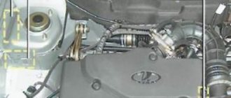
The ignition system of VAZ 2110, VAZ 2111, VAZ 2112 cars does not use a traditional distributor and ignition coil. Here, ignition module 5 (Fig. 9-30) is used, consisting of two ignition coils and high-energy control electronics. The ignition system of VAZ 2110, VAZ 2111, VAZ 2112 cars has no moving parts and therefore does not require maintenance. It also has no adjustments (including ignition timing), because The ignition is controlled by the controller. The ignition system of VAZ 2110, - 2111, - 2112 uses a spark distribution method called the “idle spark” method. The engine cylinders are combined into pairs 1-4 and 2-3 and sparking occurs simultaneously in two cylinders: in the cylinder in which the compression stroke ends (working spark) and in the cylinder in which the exhaust stroke occurs (idle spark). Due to the constant direction of current in the windings of the ignition coils, the sparking current for one spark plug always flows from the central electrode to the side electrode, and for the second from the side to the central one. Spark plugs are used type A17DVRM (for 8-valve engines) or AU17DVRM (for 16-valve engines, with a key size reduced to 16 mm). The gap between the spark plug electrodes is 1.0-1.15 mm. The ignition control in the system of VAZ 2110, - 2111, - 2112 cars is carried out using a controller. The crankshaft position sensor provides a reference signal to the controller, on the basis of which the controller calculates the firing sequence of the coils in the ignition module. To accurately control the ignition, the controller uses the following information: crankshaft speed; engine load (mass air flow); coolant temperature; crankshaft position; presence of detonation.
Gasoline vapor recovery system
This system is used on VAZ 2110, VAZ 2111, VAZ 2112 cars with a feedback fuel injection system. In the gasoline vapor recovery system, the method of vapor recovery using a carbon adsorber is used. It is installed in the engine compartment and connected by pipelines to the fuel tank and throttle pipe. There is an electromagnetic valve on the adsorber cover, which, based on signals from the controller, switches the operating modes of the system. When the engine is not running, the solenoid valve is closed and gasoline vapors from the fuel tank flow through the pipeline to the adsorber, where they are absorbed by granular activated carbon. When the engine is running, the adsorber is purged with air and vapors are sucked to the throttle pipe and then into the intake pipe for combustion during the operating process. The controller controls the purge of the adsorber by turning on the solenoid valve located on the adsorber cover. When voltage is applied to the valve, it opens, releasing vapor into the intake pipe. The valve is controlled by pulse width modulation. The valve turns on and off at a frequency of 16 times per second (16 Hz). The higher the air flow, the longer the duration of the valve activation pulses. The controller installed on VAZ 2110, VAZ 2111, VAZ 2112 vehicles turns on the adsorber purge valve when all the following conditions are met: the coolant temperature is above 75 °C; The fuel supply control system operates in a closed loop mode (with feedback); vehicle speed exceeds 10 km/h. Once the valve is turned on, the speed criterion changes. The valve will only turn off when the speed decreases to 7 km/h; Throttle opening exceeds 4%. This factor does not matter in the future if it does not exceed 99%. When the throttle valve is fully opened, the controller turns off the canister purge valve.
Operation of the fuel injection system of VAZ 2110, VAZ 2111, VAZ 2112 cars
The amount of fuel supplied by the injectors is regulated by an electrical pulse signal from the controller (electronic control unit).
The controller for the VAZ 2110, VAZ 2111, VAZ 2112 monitors data on the condition of the engine, calculates the fuel requirement and determines the required duration of fuel supply by the injectors (pulse duration). To increase the amount of fuel supplied, the pulse duration increases, and to reduce the fuel supply, it decreases. The controller has the ability to evaluate the results of its calculations and commands, as well as remember the experience of recent work and act in accordance with it. “Self-learning” of the controller is a continuous process that continues throughout the entire life of the vehicle. Fuel is supplied using one of two different methods: synchronous, i.e. at a certain position of the crankshaft, or asynchronous, i.e. independently or without synchronization with the rotation of the crankshaft. Synchronous fuel injection is the predominantly used method. Asynchronous fuel injection is used mainly in engine starting mode. The injectors on the injection engines of VAZ 2110, VAZ 2111, VAZ 2112 cars are turned on in pairs and alternately: first, the injectors of cylinders 1 and 4, and after 180° of rotation of the crankshaft - the injectors of cylinders 2 and 3, etc. Thus, each injector is turned on once per revolution of the crankshaft, i.e. twice per full engine operating cycle. Regardless of the injection method, fuel supply is determined by the condition of the engine, i.e. its mode of operation. These modes are provided by the controller and are described below. Initial fuel injection.
When the engine crankshaft begins to turn with the starter, the first impulse from the crankshaft position sensor causes an impulse from the controller to turn on all the injectors at once.
This serves to speed up engine starting. Initial fuel injection occurs every time the vehicle is started. The duration of the injection pulse depends on the temperature. On a cold engine, the injection pulse increases to increase the amount of fuel, and on a warm engine, the pulse duration decreases. After the initial injection, the controller switches to the appropriate injector control mode. Engine start mode.
When the ignition is turned on, the controller on VAZ 2110, VAZ 2111, VAZ 2112 cars turns on the fuel pump relay, and it creates pressure in the fuel supply line to the fuel rail.
The controller checks the signal from the coolant temperature sensor and determines the correct air/fuel ratio for starting. After the crankshaft begins to rotate, the controller operates in start-up mode until the revolutions exceed 400 min or the “flooded” engine purge mode begins. Engine purge mode.
If the engine on VAZ 2110, VAZ 2111, VAZ 2112 cars is “flooded with fuel” (i.e. the fuel has wet the spark plugs), it can be cleaned by fully opening the throttle while simultaneously cranking the crankshaft.
In this case, the controller does not supply injection pulses to the injectors and the engine must be “cleaned”. The controller maintains this mode as long as the engine speed is below 400 rpm and the throttle position sensor indicates that it is almost fully open (more than 75%). If the throttle valve is held almost completely open when starting the engine, it will not start because When the throttle valve is fully open, no injection pulses are sent to the injector. Operating mode of fuel supply control.
After starting the engine on VAZ 2110, VAZ 2111, VAZ 2112 cars (when the speed is more than 400 min), the controller controls the fuel supply system in operating mode.
In this mode, the controller calculates the pulse duration to the injectors based on signals from the crankshaft position sensor (rotation speed information), mass air flow sensor, coolant temperature sensor and throttle position sensor. The calculated injection pulse duration may result in an air/fuel ratio other than 14.7:1. An example would be the unheated state of the engine, because however, a rich mixture is required to ensure good driving performance. Operating mode for a closed-loop injection system.
In this system, the VAZ 2110, VAZ 2111, VAZ 2112 controller first calculates the pulse duration to the injectors based on signals from the same sensors as in the open-loop injection system.
The difference is that on car models VAZ 2110, VAZ 2111, VAZ 2112, in a feedback system, the controller also uses the signal from the oxygen sensor to adjust and fine-tune the calculated pulse in order to accurately maintain the air/fuel ratio at 14.6- 14.7:1. This allows the catalytic converter to operate at maximum efficiency. Operation of the system with sequential (phased) fuel injection.
The difference between this system and those described above is that the controller turns on the injectors not in pairs, but sequentially in the firing order of the cylinders (1-3-4-2).
The phase sensor gives the controller a signal when the 1st cylinder is at TDC at the end of the compression stroke. Based on this signal, the controller calculates the moment when each injector is turned on, and each injector injects fuel once every two revolutions of the engine crankshaft, i.e. in one full working cycle. This method allows you to more accurately dose fuel into the cylinders and reduce the level of toxicity of exhaust gases. Enrichment mode during acceleration.
The controller installed on VAZ 2110, VAZ 2111, VAZ 2112 cars monitors sudden changes in the throttle position (according to the throttle position sensor) and the signal from the mass air flow sensor and ensures the supply of an additional amount of fuel by increasing the duration of the injection pulse.
The rich acceleration mode is used only to control fuel delivery under transient conditions (when the throttle valve is moved). Power enrichment mode.
The controller monitors the throttle position sensor signal and engine speed to determine when the driver needs maximum engine power.
To achieve maximum power, a rich fuel mixture is required, and the controller changes the air/fuel ratio to approximately 12:1. On VAZ 2110, VAZ 2111, VAZ 2112 cars where a fuel injection system with feedback is used, in this mode the signal from the oxygen concentration sensor is ignored, because it will indicate the richness of the mixture. Lean mode when braking.
When braking a vehicle with the throttle closed, emissions of toxic components into the atmosphere may increase.
To prevent this, the controller monitors the decrease in the throttle opening angle and the signal from the mass air flow sensor and promptly reduces the amount of fuel supplied by reducing the injection pulse. Fuel supply cut-off mode when engine braking.
When braking with the engine in gear and clutch engaged, the controller can completely turn off the fuel injection pulses for short periods of time.
The fuel supply is turned off and on in this mode when certain conditions are met regarding coolant temperature, crankshaft speed, vehicle speed and throttle opening angle. Supply voltage compensation.
When the supply voltage drops, the ignition system may produce a weak spark, and the mechanical movement of “opening” the injector may take longer.
The VAZ 2110, VAZ 2111, VAZ 2112 controller compensates for this by increasing the time of energy accumulation in the ignition coils and the duration of the injection pulse. Accordingly, as the battery voltage increases (or the voltage in the on-board network of a VAZ 2110, VAZ 2111, VAZ 2112), the controller reduces the time of energy accumulation in the ignition coils and the injection duration. Fuel cut-off mode.
When the ignition is turned off, fuel is not supplied by the injector, which prevents self-ignition of the mixture when the engine is overheated. In addition, fuel injection pulses are not supplied if the controller does not receive reference pulses from the crankshaft position sensor, i.e. this means the engine is not running. The fuel supply is also switched off when the maximum permissible engine speed of 6510 rpm is exceeded to protect the engine from over-torque. Cooling system fan control. The cooling system fan is turned on and off by the controller depending on the engine temperature, crankshaft speed, air conditioning operation (if there is one on a car of the VAZ 2110 family) and other factors. The cooling system fan is turned on using an auxiliary relay located under the instrument panel console on VAZ 2110, VAZ 2111, VAZ 2112 cars on the right side. When the engine is running, the electric fan turns on if the coolant temperature exceeds 104°C or a request is given to turn on the air conditioning. The cooling system fan of the VAZ 2110, VAZ 2111, VAZ 2112 turns off after the coolant temperature drops below 101°C, after turning off the air conditioner or stopping the engine.
Video
The video shows the process of replacing the timing belt on a VAZ 2112. Filmed by the ExpertR channel.
Replacing the timing belt VAZ 2112 1.6 16 cl.
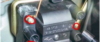
1. Remove the timing belt protection. The timing belt guard is secured with six bolts. Remove the chip from the crankshaft sensor, unscrew one bolt and remove the sensor.
2. One tooth is missing on the pulley, this is not without reason, this allows the crankshaft sensor to determine the top dead center, and also allows you to block the crankshaft in order to unscrew and tighten the pulley mounting bolt.
3. This is done like this: the pulley is aligned with the hole for the crankshaft sensor and through the hole for the sensor, a suitable size tube or other suitable object is inserted, in my case it is a hexagon, the pulley is blocked, and then unscrewed and removed.
4. Loosen the tension roller nut and remove the old timing belt.
5. Install a new belt, the belt can be installed by turning the right camshaft with a wrench, or you can remove the tension roller, whichever is more convenient for you.
6. Tighten the pulley mounting bolt back and align the timing belt drive gear according to the marks. If there are no marks on the oil pump housing, put marks on the flywheel and, using a chisel, make a mark on the oil pump, this will be more convenient.
7. Align the marks of the camshaft pulleys so that the timing belt drive gear does not go astray
8. Using a special wrench, tighten the belt with a tension roller. If there is no key, don’t be upset, you can tighten it with two nails and a screwdriver between them, or you can take a steel fork, remove the two middle teeth completely, and shorten the two outer ones in half and bend them. Be sure to remember to tighten the tension pulley nut. (To tighten the belt, turn the tension roller counterclockwise (about 10–15°); to loosen it, turn it clockwise)
VAZ-2111 diagram
The free collection of materials to help auto electricians contains all the necessary documentation on the electrical equipment of the VAZ-2111 car - general circuit diagram, switching system, electronic engine control module, relay block with fuses and other components. The VAZ 2111 car is a station wagon (production from 1998 to 2014), which is a modernized concept of the rear-wheel drive VAZ-2104. Here the wiring diagram for the injector and a number of other components have been slightly changed, as can be seen from the electrical diagrams and harnesses.
Modifications of VAZ-2111
- VAZ-21111 with an opening rear door, station wagon with a 1.5-liter carburetor engine.
- VAZ-21110 is equipped with an injection 8-valve engine with a working volume of 1.5 liters.
- VAZ-21112 station wagon with an injection 8-valve engine with a volume of 1.6 liters and a power of 80 hp. With.
- VAZ-21113 with a 16-valve injection engine with a volume of 1.5 liters.
- VAZ-21114 with a 16-valve injection engine 1.6 liters 89 horsepower.
- VAZ-21116 - 04 all-wheel drive station wagon equipped with a 2-liter Opel C20XE engine with a capacity of 150 horses. It featured enlarged wheel arch cutouts, a redesigned bumper skirt with integrated fog lights and an updated aerodynamic shield over the rear.
- VAZ-2111-90 "Tarzan-2" all-wheel drive station wagon built on the basis of the VAZ-2111, produced since 1999. Like the previous generation of Tarzans, the body of the VAZ-2111 car was placed on a frame from the Niva, the rear suspension of the car was independent.
Injector types
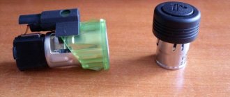
The injector controls fuel injection and can also control the ignition.
On all new injection machines, the ignition is set by a computer and regulated by filling in different firmware. But this was not always the case, and on older cars, the same Japanese from the 90s, the computer regulates only fuel injection, and the ignition timing is set using a distributor and is set in the same way as on old Lada models, and depending on the speed The ignition timing is adjusted using a more complex vacuum system than on carburetor Zhigulis. Sometimes, one tube breaks, and during operating mode the traction may disappear; you will have to look for and correct this defect. But let’s return to more modern ignition systems that are controlled using a computer, especially since these were the ones that were originally installed on the injection VAZ.
General electrical circuit VAZ-2111
- Block lights;
- Sound signal;
- Engine cooling fan electric motor;
- Starter VAZ-2111;
- Accumulator battery;
- Generator;
- Reversing light switch;
- Electric drive for locking the right front door lock;
- Power window relay;
- Starter activation relay;
- Heater motor;
- Micromotor-reducer for heater damper drive;
- Windshield washer motor;
- Washer fluid level sensor;
- Electric drive for locking the left front door lock;
- Right front door power window switch;
- Electric trunk lock;
- Additional resistor for heater fan motor;
- Windshield wiper gear motor;
- Left front door power window switch;
- Electric power window of the right front door;
- Door lock system control unit;
- Outdoor lighting switch;
- Brake fluid level sensor;
- Electric window lifter of the left front door;
- Indicator lamp for turning on the fog light;
- Fog light switch;
- Instrument cluster;
- Rear window heating indicator lamp;
- Rear window heating switch;
- Understeering's shifter;
- Fog light relay;
- Ignition switch;
- Mounting block;
- Illumination lamp for heater control levers;
- Hazard switch;
- Automatic heater control system controller;
- Glove compartment lamp;
- Glove compartment lamp switch;
- Cigarette lighter;
- On-board control system display unit;
- Ashtray lighting lamp;
- Socket for portable lamp;
- Instrument lighting switch;
- Electric drive for locking the right rear door;
- Right rear door power window switch;
- Watch VAZ-2111;
- Electric window lift of the right rear door;
- Brake light switch;
- Electric window lifter of the left rear door;
- Left rear door power window switch;
- Electric drive for locking the left rear door;
- Side direction indicators;
- Parking brake warning lamp switch;
- Luggage compartment lighting;
- Individual lighting lamp;
- Interior lighting;
- Heating system temperature sensor;
- Switches in the front door pillars;
- Switches in the rear door pillars;
- Exterior tail lights;
- Interior tail lights;
- License plate lights;
- Rear window wiper motor;
- Rear window washer motor;
Fuse and relay box
The VAZ-2111 relay and fuse mounting block is located on the left side of the steering column in the instrument panel. To access the unit, press the latch switch and lower the unit down.
K1 - lamp health monitoring relay;
K2 - windshield wiper relay;
KZ - relay-interrupter for direction indicators and hazard warning lights;
K4 - headlight low beam relay;
K5 - headlight high beam relay;
K6 - additional relay VAZ-2111;
K7 — relay for turning on the heated rear window;
K8 - rear fog lamp relay;
F1-F20 - fuses
| Number | Current, A | Description of fuses |
| F1 | 5 | License plate lamps. Instrument lighting lamps. Side light indicator lamp. Trunk light. Left side marker lamps |
| F2 | 7,5 | Left headlight (low beam) |
| F3 | 10 | Left headlight (high beam) |
| F4 | 10 | Right fog lamp |
| F5 | 30 | Door window motors |
| F6 | 15 | Portable lamp (socket) VAZ2111 |
| F7 | 20 | Engine cooling fan electric motor. Sound signal |
| F8 | 20 | Rear window heating element. Relay (contacts) for turning on the heated rear window |
| F9 | 20 | Recirculation valve*. Windshield and headlight cleaners and washers (wiper protection). Relay (coil) for turning on the rear window heating |
| F10 | 20 | Spare |
| F11 | 5 | Starboard side marker lamps |
| F12 | 7,5 | Right headlight (low beam) |
| F13 | 10 | Right headlight (high beam). High beam warning lamp |
| F14 | 10 | Left fog lamp |
| F15 | 20 | Electrically heated seats. Trunk lock lock |
| F16 | 10 | Relay-breaker for direction indicators and hazard warning lights (in hazard warning mode). Hazard warning lamp |
| F17 | 7,5 | Interior lighting lamp. Individual backlight lamp. Ignition switch illumination lamp. Brake light bulbs. Clock (or trip computer) |
| F18 | 25 | Glove box lighting lamp. Heater controller (heater fuse). Cigarette lighter fuse for VAZ 2110, VAZ 2111, VAZ 2112. |
| F19 | 10 | Locking door locks. Relay for monitoring the health of brake light lamps and side lights. Direction indicators with warning lamps. Reversing lamps. Generator excitation winding. On-board control system display unit*. Instrument cluster. Clock (or trip computer) |
| F20 | 7,5 | Rear fog lamps |
A fog lamp fuse is installed in the niche of the instrument panel behind the mounting block. The central locking fuse is located behind the fuse box in a plastic box. And additional relays and fuses (all 15 A) are located in the cabin on the right side of the instrument panel behind the side trim attached with two screws.
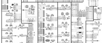
- 1 — ignition module, controller;
- 2 — canister purge valve, vehicle speed sensor, oxygen concentration sensor (heating), air flow sensor VAZ-2111;
- 3 - fuel pump relay, fuel pump fuse, injectors.
- 4 — electric fan relay;
- 5 - fuel pump relay,
- 6 - main relay (ignition relay).
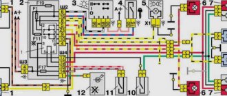
Relay and fuse box diagram
This is a schematic diagram of the VAZ 2111 relay and fuse mounting block. The outer number in the wire tip designation is the block number, and the inner number is the conventional number of the plug.
| Block | № | Color | Electrical circuits |
| Ш1 | 1 | ZhCh | fog lamp (left) |
| 2 | GP | trunk lock motor, heated seats | |
| 3 | R | door lock relay | |
| 4 | ABOUT | power window relay | |
| 5 | ZhP | fog light relay | |
| 6 | AND | fog lamp (right) | |
| 7 | MS | power window relay | |
| 8 | — | reserve | |
| Ш2 | 1 | — | reserve |
| 2 | — | reserve | |
| 3 | — | reserve | |
| 4 | H | weight " - " | |
| 5 | ZhP | size (left rear) | |
| 6 | Warhead | outdoor light switch | |
| 7 | — | reserve | |
| 8 | ZhCh | license plate lamps, off instrument lighting | |
| 9 | KP | size (right rear) | |
| 10 | TO | size (right) | |
| 11 | ZhG | email windshield wiper motor, windshield wiper and washer switch. | |
| 12 | Z | outdoor light switch | |
| 13 | ABOUT | fog light switch | |
| 14 | Emergency | hazard switch | |
| 15 | — | reserve | |
| 16 | GP | Ignition switch (terminal 15), steering column switch | |
| 17 | R | windshield wiper and washer switch | |
| 18 | JV | steering column headlight switch | |
| 19 | — | reserve | |
| 20 | — | reserve | |
| 21 | AND | size (left) | |
| Ш3 | 1 | midrange | low beam (left headlight) |
| 2 | — | reserve | |
| 3 | WITH | low beam (right headlight) | |
| 4 | R | generator (cl. 30) | |
| 5 | TO | generator (cl. 30) | |
| 6 | TO | generator (cl. 30) 2111 | |
| Ш4 | 1 | PZ | on-board display system |
| 2 | GO | hazard switch | |
| 3 | IF | hazard switch | |
| 4 | H | weight " - " | |
| 5 | PG | portable lamp plug | |
| 6 | Salary | heated rear window switch, heated rear window lamp | |
| 7 | — | reserve | |
| 8 | — | reserve | |
| 9 | — | reserve | |
| 10 | ZhZ | steering column washer and windshield wiper switch | |
| 11 | B | email windshield wiper motor | |
| 12 | BW | steering column washer and windshield wiper switch | |
| 13 | GB | steering column switch, ignition switch lamp | |
| 14 | BP | brake lights, clock, interior lamp | |
| 15 | P | brake lights | |
| 16 | RP | off brake lights | |
| 17 | ABOUT | generator (cl. 30) VAZ-2111 | |
| Ш5 | 1 | AF | high beam (left lamp) |
| 2 | JV | rear window heating element | |
| 3 | G | heater controller, glove compartment lamp | |
| 4 | Z | high beam (right lamp) | |
| 5 | ZhG | Windshield wiper motor, SAUO recirculation valve | |
| 6 | PB | email cooling fan, beep |
To locate the faulty fuse, use the table of circuits protected by fuses. Before this, of course, you need to find the cause of the blown fuse, eliminate it, and only then install a new one. The table shows the circuits that each fuse protects, but on each model some of them may not be installed due to the lack of certain devices (for example, power windows, lock drives and other units).
Source
Where does the compression go?
Air under pressure can break through in several directions at once - through the pistons with piston rings, or through the cylinder head - through the intake or exhaust valves.
After repairing an engine by incompetent craftsmen, it happens that the valve timing is set incorrectly, and the valves seem to close, but not when they should - during the compression stroke the valves remain slightly open - this may be enough for air to escape, but the displacement is not enough, so that the valves come into contact with the piston and bend.
Another example is coking and ring sticking. In this case, the compression valves lie in the grooves and gases easily pass through them, because there is no seal. In this case, usually the oil scraper rings work, so the oil does not seal the resulting cracks. This is a similar example to when oil is washed off the cylinder walls by unburned fuel, but here the oil is simply removed by oil scraper rings.
In case of mechanical damage, valves are more likely to suffer - they can burn, bend, fall out, the valve seat can burn out - in general, there will be no necessary mating of parts, and, accordingly, gases will escape. The valve can bend for various reasons - the same belt will break, and the valves will meet the piston in an unequal battle. The result of this battle is obvious, so change the belt on time.
Pistons are also susceptible to all kinds of damage. If you refuel with low-quality gasoline, detonation will occur, as a result of which the bridges between the ring grooves break. If foreign objects get into the combustion chamber, mechanical shocks to the piston and its partial destruction are possible. Piston rings can also break due to the same detonation , and if you drive without an air filter, the rings will wear out to such a state that they become wadded, and the gaps will increase.
The problem is either in the pistons/piston rings or in the valves, we sorted it out.
If the compression is completely gone. Most likely, the cause will be damage to the valves, as they will no longer close and allow gases to pass through. This is easy to check. When the rings wear out, gases escape through the ring-cylinder wall interface. If you drop a little motor oil, 10 milliliters, into the cylinder, it will close the cavities around the piston and the compression will increase during the next measurement. If it hasn’t grown, it’s almost a guarantee that the valves are to blame, since you can’t close them with oil.
If the compression has dropped a little. Here, wear of the piston group will most likely be to blame. Again, add oil and see the result.