After the active introduction of an injection power system on various VAZ models, the overall design of the car became more complex. As you know, an injector, unlike a carburetor, cannot dose fuel itself. To solve the problem, control of the fuel injectors was transferred to the electronic engine control unit (ECU) or controller, better known as a computer or “brains”.
On the one hand, by installing the brains in the VAZ, the manufacturer made the engine more economical and less toxic. However, on the other hand, the control system has become more complex, and a large number of additional solutions and devices have appeared. Next, we will look at what features the VAZ electronic unit has, where it is located on different models, what functions the ECU performs, etc.
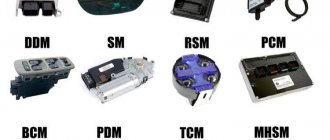
VAZ injection models: ECU, controller purpose and features
So, the injector, which is actually represented by electronic-mechanical injectors, cannot dose fuel on its own. The engine control unit is responsible for the correct operation of the injectors. In turn, this unit is actually the electronic engine control system (ECM).
This system is based on a group of sensors that send their signals to the ECU, then the unit processes the information and then generates control signals to the actuators. The main task is to make the engine operate in optimal mode and maintain optimal operating parameters of the internal combustion engine, taking into account constantly changing conditions.
So, the ECU receives signals from a large number of sensors, after which, using algorithms “hardwired” into the unit’s memory, the amount of fuel required for the engine to operate in optimal mode is calculated. The ECU also controls the moment of spark formation in the cylinders, replacing the ignition system on a car with a carburetor.
The ECU also conducts self-diagnosis and checks the condition of the engine, recording failures, deviations and irregularities in operation. If the controller cannot correct the situation, then an error is recorded in the memory, and the driver receives a notification in the form of a “check” icon on the instrument panel.
- As for the sensors, thanks to their presence, the ECU determines the engine operating mode, speed, and load on the internal combustion engine. For example, the MAF (mass air flow sensor) allows you to obtain data to calculate the amount of fuel, taking into account the amount of air entering the cylinders.
(the temperature sensor determines the temperature of the internal combustion engine, thereby indicating how the fuel will burn in a cold and warm engine). TPS (throttle position sensor) shows how hard the gas pedal is pressed.
Also, the crankshaft sensor (CPCV) and the camshaft sensor (CPR) allow the computer to determine the time of fuel injection into the cylinders, the time of creation of a spark on the spark plugs in each individual cylinder, etc. In fact, it turns out that later versions of the ECU are able to calculate the amount of fuel for each individual cylinder in order to obtain stable and efficient engine operation, as well as control the ignition.
If fuel combustion becomes explosive, the explosion is detected by the engine knock sensor (). The control unit adjusts the mixture and changes the ignition angle to avoid detonation. If the ECU cannot solve the problem, the “check” lights up and the error is recorded in the ECU’s memory.
Even on later VAZ models, the VAZ controllers and firmware themselves changed, since oxygen sensors paired with a catalyst were used in the design. These sensors determine the efficiency of fuel combustion by recording the amount of oxygen in the exhaust. So, for this reason, you need to take into account that ECUs of different generations are different.
For example, older versions did not have support for a phase sensor (DPRV); injection took place into the intake manifold, and not into each cylinder individually. These ECUs are the central injection control unit. Later, blocks appeared that prepared the mixture for each individual cylinder (distributed injection ECU).
Subsequently, support for an oxygen sensor was implemented, then two oxygen sensors (taking into account stricter toxicity standards) for more efficient use of the catalytic converter.
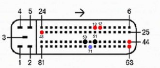
In any case, when selecting an ECU for a car, you need to know exactly a number of features: block and firmware version, ECU pinout, etc. To put it simply, the brains of a VAZ 2114 may differ from the ECU of a VAZ 2115, and the control unit of a VAZ 2110 will not work on a VAZ 2108 injector.
This means that Kalin’s brains cannot be used as a replacement for the Priora ECU, although one and the other unit will be VAZ ECUs. It turns out that it is important to know which unit is installed on a particular car. To determine this, you need to understand where the VAZ ECU is located, and then study the markings on the device. Let's figure it out.
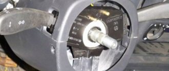
Immobilizer problems
Due to the device's access to the engine starting system, its components are not permitted. A sudden stop in the supply of fuel and power to the engine means a blockage on the part of the anti-theft system. At the time of development of this system, many nuances with possible interference from other devices were not taken into account. This leads to situations where, when a smartphone is nearby, the exchange of information between the chip and the unit is interrupted. Disabling the device does not always help, so a complete replacement of the system with a new one is required. Independently disabling the immobilizer on a VAZ 2114 is one way to avoid possible problems with starting the engine.
Where is the VAZ ECU located and the interchangeability of control units
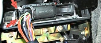
First of all, to determine the type of control unit, you need to find its installation location in the car. To do this, you should study the manual. As an example, let's look at the VAZ 2108 - 2115. On these cars, the ECU is located in the passenger compartment, on the front right, slightly below the glove compartment.
By the way, this information is also useful for computer diagnostics, since you need to know where you can connect to the diagnostic connector installed in various places on a particular model.
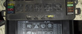
Diagnostic connectors VAZ 2108 - 21099 with a low panel are located near the ECU, under the glove compartment. Models VAZ 2108 - 21099 with a high panel, as well as 2113 - 2115, have a connector inside the center console. The VAZ 2108 - 2115 version with the so-called Europanel has a connector on the panel, and it is located closer to the passenger door.
- As for the units themselves, VAZ 2108 - 2115 of different years of production have different ECU models. For example, the most popular ECU January 4 was installed on early models of injection engines with central injection into the intake manifold.
Version January 5 - 6 are ECUs with distributed injection, but without oxygen sensor support. The January 7 control unit has appeared on cars since 2007, supports all sensors, and effectively controls the engine.
Let us also add that in addition to January, different generations of GM units were actively used at VAZ, being an analogy of January 4 - 7. The same can be said about Bosch or Itelma ECUs. Taking into account all the features, interchangeability is possible, but you need to select analogues that are suitable for the class, version, number of supported sensors, etc.
The fact is that each model is only suitable for a certain combination of engine and sensors, as well as wiring and firmware. This means that different models, even within the same family, can only be installed taking into account full compatibility.
Let us note once again that the types of ECUs on VAZs differ. It turns out that you cannot put January 5.1 instead of January - 4 or GM-09 SAMARA, however, for January 5.1 there is interchangeability with VS (Itelma) 5.1 or Bosch M1.5.4. In turn, the Bosch M7.9.7 ECU is not compatible with previous units, but can be replaced with January 7.2 Itelma or Avtel.
To accurately identify the ECU, just remove the instrument panel frame from the side and write down the ECU number. Also, if you have a BC, you can optionally view the version and type of the ECU, as well as the firmware number of the unit
How to remove the Lada Granta ECU step by step instructions
In order to remove the Lada Granta ECU, you will need to perform the following procedure:
- De-energize the system by removing the terminals from the car battery
- The ECU controller is located under the glove compartment under the passenger's feet and hidden under the upholstery. The upholstery is attached to the body on the right with a self-tapping screw. We unscrew this screw.
- Next, we move the sheathing away from the floor with our hands as shown in the figure.
- Now we bend the soundproofing material to the side
- After unscrewing the nuts, we move the ECU away from the body.
- Now we squeeze the clamp of the wire harness fastening bracket and fold back the bracket.
- We disconnect the connector from the block and similarly disconnect the second harness with wires, after which we remove the ECU from the car. Make the necessary repairs, then install in the reverse order.
Step-by-step instructions for removing the brains of a Lada Granta - video
Frequent malfunctions of the VAZ electronic control unit
Considering that the controller is a complex electronic device, failure of the ECU cannot be ruled out. As a rule, the causes of ECU malfunction can be different, ranging from mechanical damage to software failures.
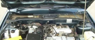
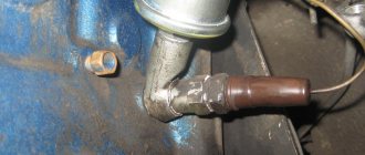
For example, a common cause of breakdowns is overheating or liquid ingress. As practice shows, on the Lada Samara the ECU is located near the heater radiator. It is not difficult to guess that a radiator leak and coolant entering the controller often disables this device.
We also recommend reading the article about what the ELM327 diagnostic adapter is. From this article you will learn about the purpose, functionality, and features of selecting the ELM327 scanner.
Also, voltage surges in the on-board network lead to the fact that individual parts in the control unit burn out, and the memory bank with firmware suffers. For example, this happens if the battery terminals come loose. Also, poor contact with the spark plugs or high resistance of the explosive wires form an electromotive force in the primary winding of the ignition coil. The result is a breakdown of the output transistors of the control unit.
In this case, the check engine light does not always light up on the panel, but the engine malfunctions. In such a situation, when no other causes have been identified, what is needed is not diagnostics of the engine and systems, but professional diagnostics of the car's ECU, which can only be performed by an experienced specialist. Often, after checking, the unit may need to be replaced, since ECU repair is often not recommended.
We flash the Itelma M74 (Lada Granta) ECU with our own hands
In order to independently flash the Itelma M74 ECU, which, as we already know, is installed on the Lada Grant, you need to perform the following procedure:
- Disconnect the battery mass.
- Remove the ECU block. The connectors are disconnected like this:
- Let’s make a “spider” like this (I recommend signing the wires)
- We connect the connectors: Connector 1 (large) J1 - switchable voltage (K15) (12V) - second switch B2 - programming permission (12V) - first switch A4 - programming permission (12V) - first switch Connector 2 (Small) G2;G3; G4 - Ground (can be connected to any) H1; H2 - non-switchable voltage (K30) F2 - switchable voltage (K15) (12V) - second switch D2 - K-Line
- here's EL. diagram (many people write that they are flashing, but there is no diagram anywhere)
6. It is not recommended to apply voltage to all wires at the same time! It is necessary step by step through a double switch.
7. 4-And so the whole circuit is assembled and the KKL VAG-COM cord is inserted into the USB PC. Here is the voltage supply sequence
- Apply voltage (+12 V) to H1; H2 (throw the hooks onto the battery)
- Turn on the first switch (programming permission) B2 A4
- We launch the WinFlashECU program (-Select M74, -select the port number on which KKL VAG-COM hangs -it’s better to set the speed to the minimum)
- Next, turn on the second switch (which is on the “switch-off voltage”) F2 J1
- Communication with the ECU should appear (this is an indicator that the circuit is assembled correctly)
- Then we save copies of your “firmware and immo” on your computer, click
- Reading EEPROM and Reading ECU just in case (at the same time we check how everything works)
- code copying finished
- click ECU programming, look for the required firmware on your computer and download
Let's sum it up
As you can see, by analogy with various foreign cars, VAZ injection engines of different generations are also equipped with controllers of various types. Early versions have simple solutions that are responsible for simple mixture formation and work with a small number of sensors.
We also recommend reading the article about how the automatic transmission ECU works. From this article you will learn about the features, principles of operation, purpose and breakdowns of the electronic control unit of the automatic transmission.
At the same time, more modern control units are distinguished by support for distributed injection, more flexible control of the ignition system, as well as the ability to interact with oxygen sensors, etc.
For this reason, if it is necessary to replace a VAZ ECU, it is necessary to carefully approach the selection of the control unit for replacement. Moreover, even if the blocks are compatible in terms of version, type and connectors, the firmware version must also be taken into account.
Only after all the nuances have been taken into account can you expect that the engine under ECU control will operate correctly and without failures, and the owner himself will receive stable operation of the power unit and systems, environmental friendliness and maximum efficiency from the engine in different operating modes of the car’s engine.
For this we need:
Universal adapter KL-Line BM9213 USB MASTER KIT for tuning a car with an injection engine, you will not chip the carburetor with it,
You can read more about it and how to purchase it here. For the adapter, the driver for the virtual COM port for Win XP, Vista can be downloaded here, you can also use another adapter VAG COM USB KKL v409.1 which can be purchased from our partners, this is the one The KK-Line adapter is exclusively in the case and for funny means.
Next, for flashing the chip firmware, we will need ChipLoader 1.96; you can also use the newest version of ChipLoader 1.97.7, and the previous one works smoothly, so I don’t see the need to use the new one.
in the Help > Help tab you will find the User Guide, also go to options and uncheck all the boxes as shown in the figure above. In order for the block to start sewing, it needs to be modified according to the annotations in the User Manual
, everything is carefully described there.